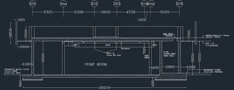
Creating Kitchen layout, Hatching of Architectural elements and sectional view of an Industrial Building in AutoCad
WEEK 10 CHALLANGE REPORT AUTOCAD
-
Aim is to create the layouts of the kitchen and provide hatches pattern as shown in the figure wherever required. Need to create blocks out of units and appliances of the kichen.
-
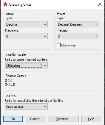
First we open a file and set the units of the working space usin command : Units.
-
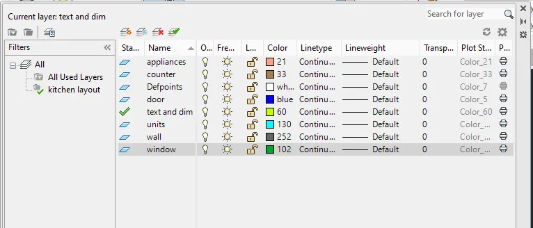
Next I create Layers using command: LA Layers
-
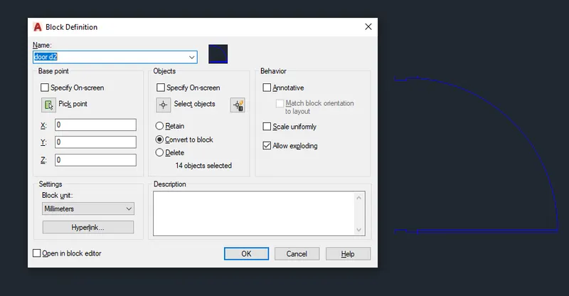
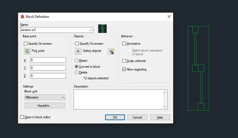
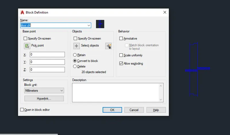
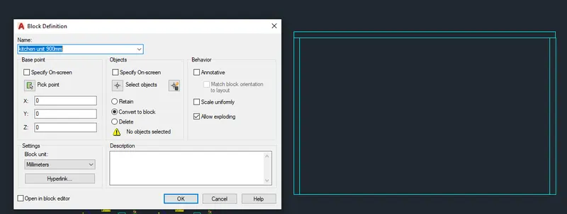
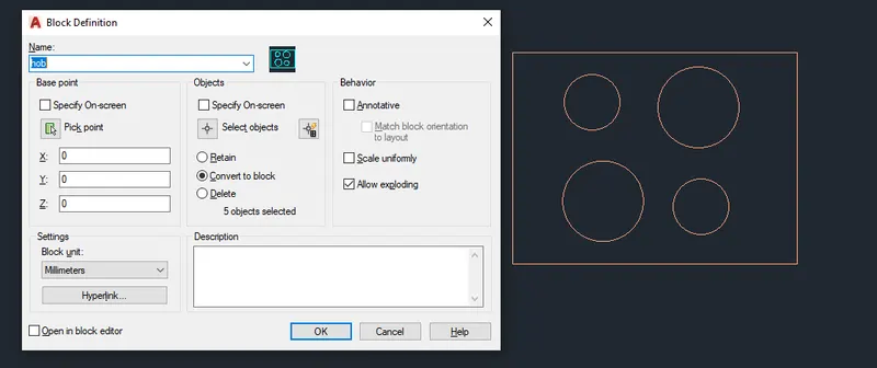
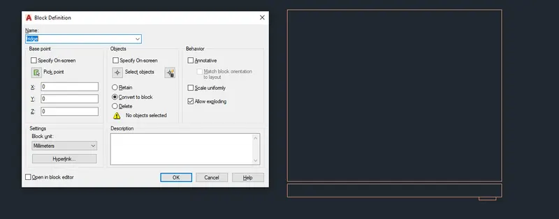
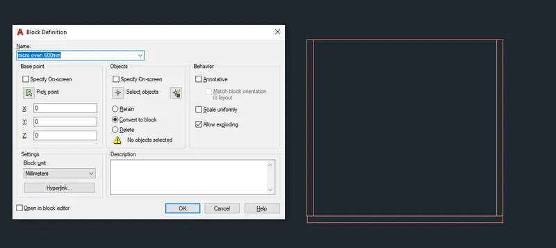
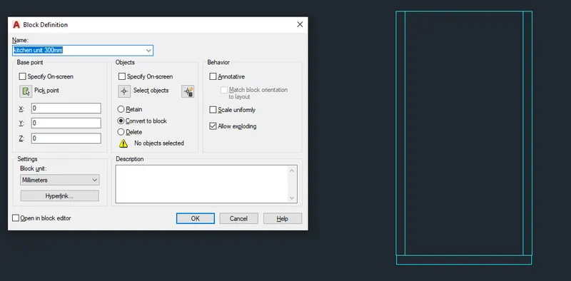
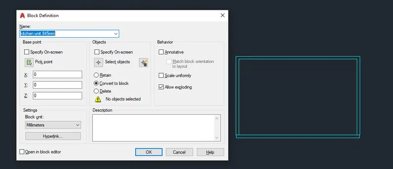
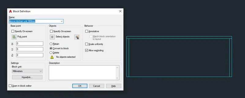
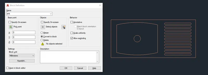
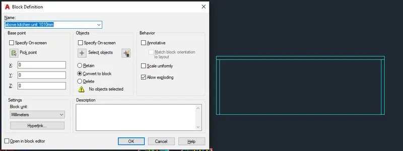
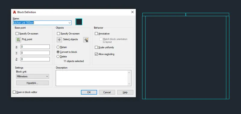
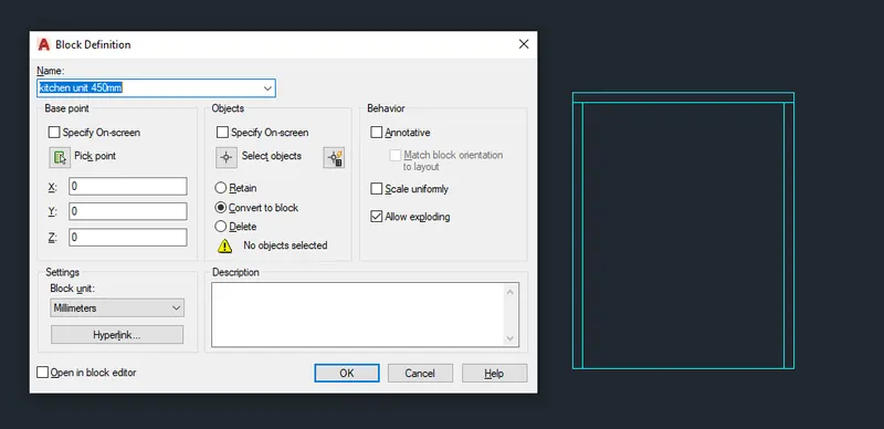
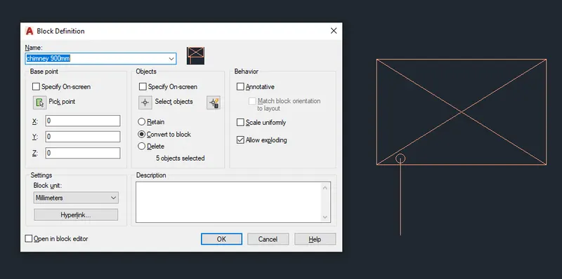
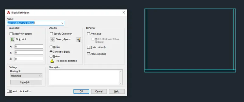
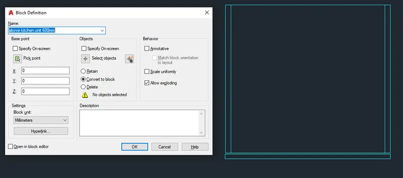
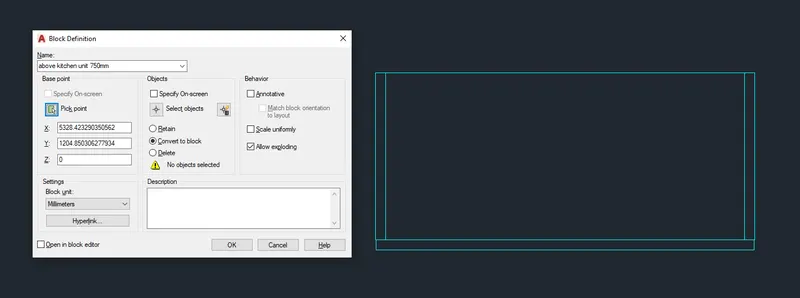
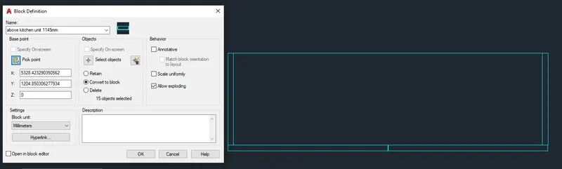
First step before starting with the kitchen layout is to create the blocks which will be used inside the layout.
Now using respectiv layers I create one by one all the blocks which will help to sketch the kitchen layout.
-
To do soo I use command as rectangular, circle, trim, line, offset, mirror,fillet, arc...
-
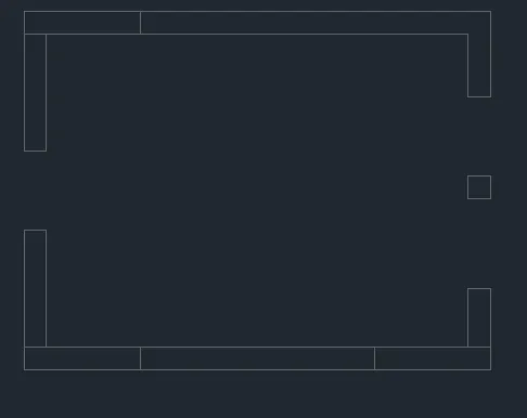
Now using commands: rectangular, offset, trim, line…
I draw the walls of the kitchen layout.
-
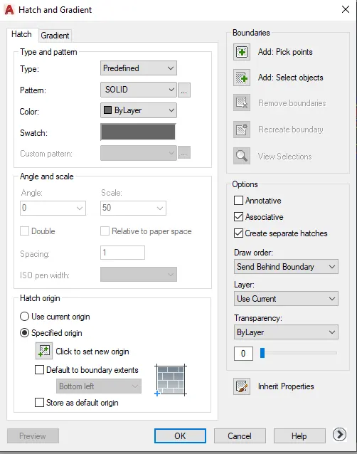
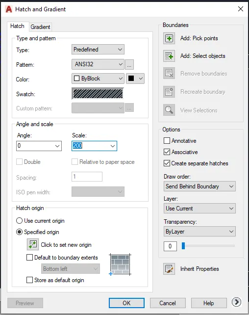
Using command: H for Hatch I choose pattern Solid and ANSI 32 as shown to hatch the walls of the kitchen.
-
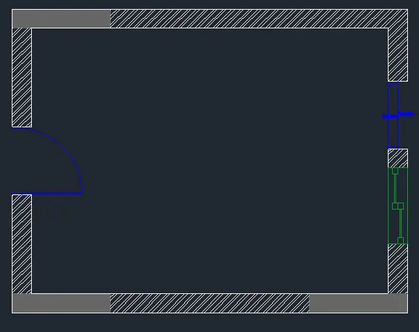
After Hatching and using command:Insert to insert the block of the doors and the window, this is the sketch of the kitchen at this step.
-
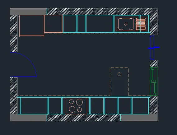
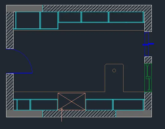
Using command: Insert I insert all the kitchen unit and appliance blocks.
-
This is the sketch of the kitchen before dimension and text.
-
I create a text style Standard of hight 50 and at the properties I change the height of the text as shown from 40-100mm.
Text Style for the Text and dimensions of the plan
Command: STYLE> Standard>font name: romans.shx
height: 50
Dimmension Style
Ribbon> Annotate> Dimensions>Standard>Modify>
>Lines: √ Fixed length extension lines
Length: 1
>Simbol and Arrows
Arrow size 10.18
>Text Style Standard
>Text Alignment Alignet with dimension line
>Text placement Centered
>Unit Format Decimal
>Precision 0 ok
-
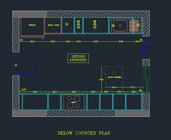
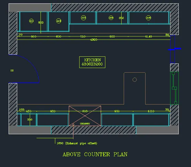
After adding dimensions and text this is the final sketch of the kitchen layout.
2.Aim is to attach external reference: week 7 dwg material, and use directions and dimensions from the plan and section to create the elevation of the plan as shown.
I need to apply proper Hatch to the windows, doors, walls and other architectural elements.
-
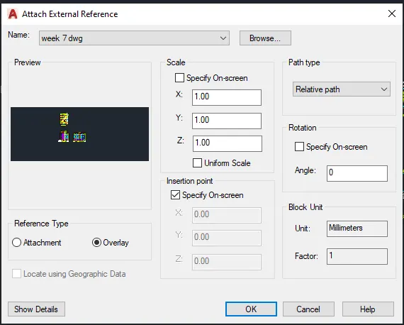
As a first step I use command: XREF External Reference to attach week 7 dwg material.
-
At External Reference table, I right click week 7 dwg material, and press Bind>Bind type:Bind>ok
-
In this way I can explode the material and work withit and with the layers as well.
-
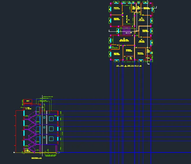
I user command:RAY to create direction lines from the plan and section.
-
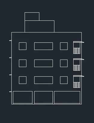
Using command: line, rec, offset, trim…and with the help of the direction lines I sketch the elevation of the plan and I am at this point of the drawing.
-
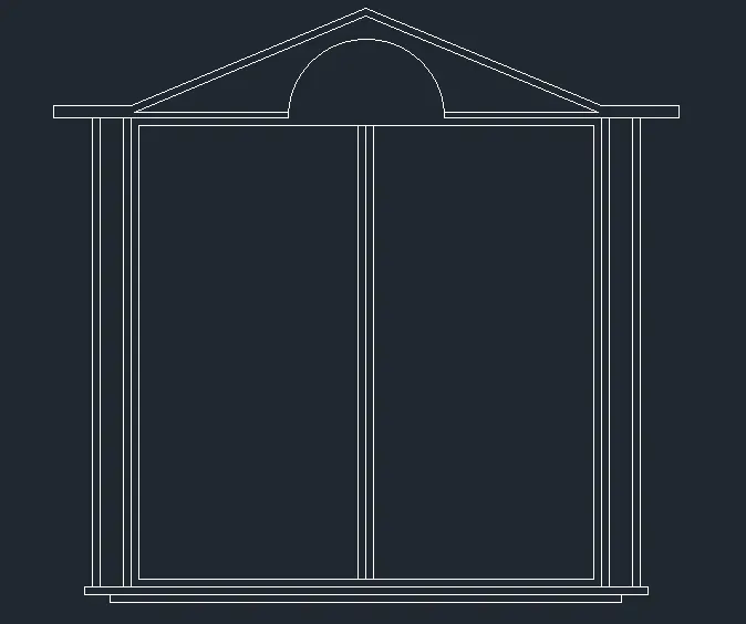
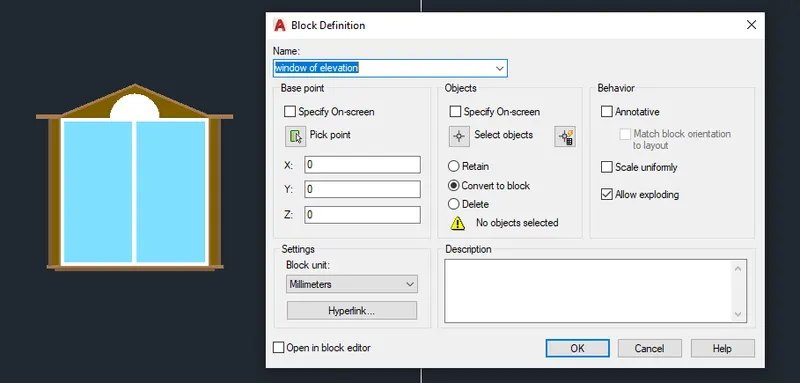
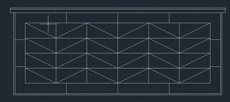
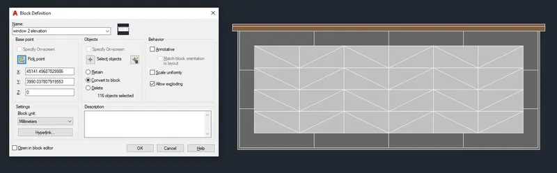
Now I sketch the windows and create them as blocks.
-
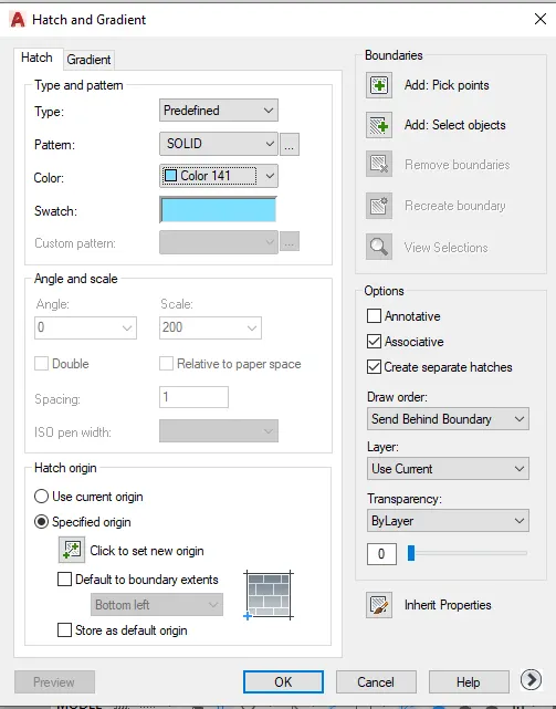
Using commands: line. Rec, offset, trim , hatch with pattern solid and different colours, block...
-
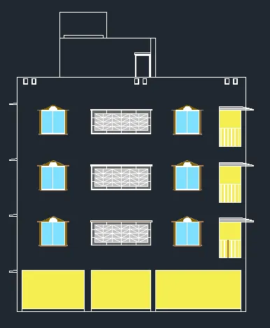
I use command: insert to insert the window blocks.
I use command : hatch to hatch the inner walls.
-
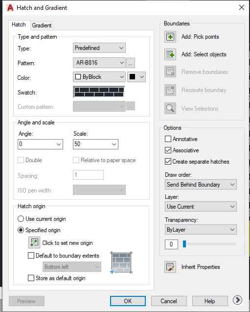
To hatch the front wall of the elevation, I use pattern AR-B816 (bricks pattern) with a scale 50 and I set the origine at bottom left of the elevation.
-
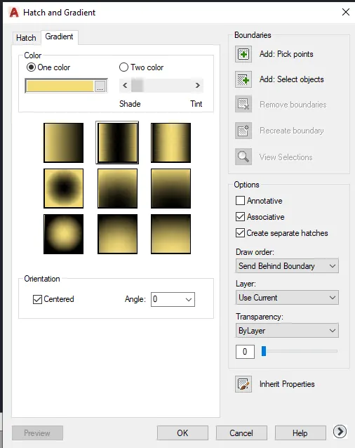
Then I use command: Gradient to add shaded colour to the brick wall. I use Tint 25%.
-
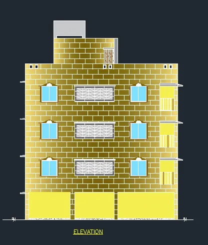
After applying all the hatches and gradient this is the final look of the elevation.
3.Aim is to create the section view of an industrial building as shown. Need to provide hatch patterns, dimension and text wherever required.
-
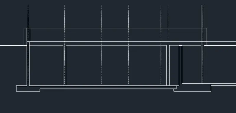
I start with creating the axis of the industrial building, and then sketching the foundation and walls of the section of the basement using commands: offset, line, trim, fillet...
-
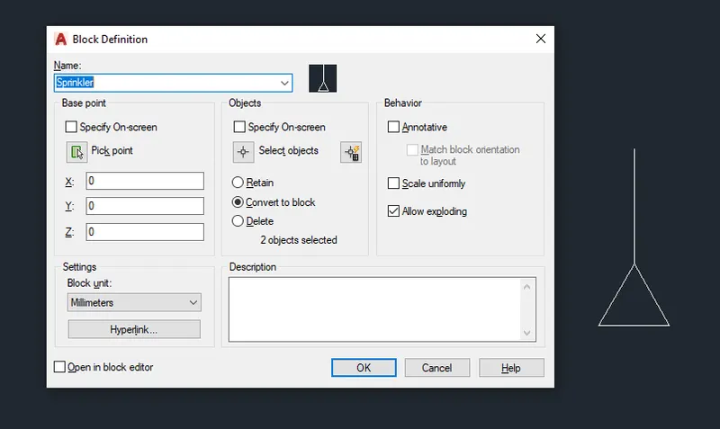
While drawing the rest of the elements of the industrial building section, I create a block named Sprinkler.
-
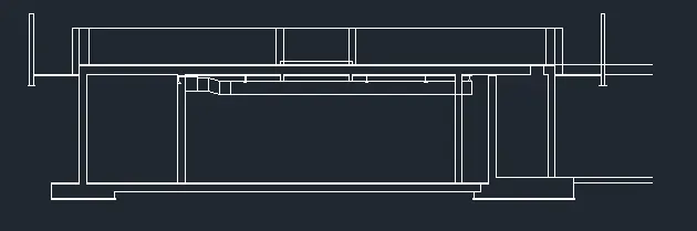
After adding all the elements of the section this is the sketch of the section of the industrial building before hatch, text and dimensions.
-
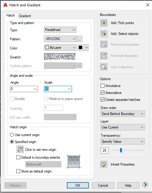
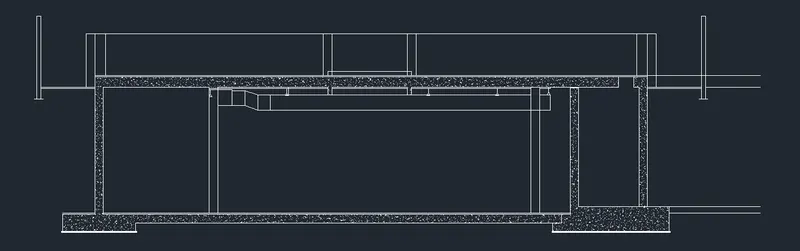
I use command Hatch with pattern AR-CONC with a scale 50 to hatch the walls of the industrial building.
-
This is the drawing after hatching.
-
Now is left to ad dimmension and text.
Text Style for the Text of the axis and dimensions
Command: STYLE> Style1>font name: romans.shx
height: 400
Text Style for the Multileader
Command: STYLE> Style2>font name: romans.shx
height: 150
Dimmension Style
Ribbon> Annotate> Dimensions>Style1>Modify>
>Lines: √ Fixed length extension lines
Length: 1
>Simbol and Arrows
Arrow size 145.18
>Text Style Style1
>Text Alignment Alignet with dimension line
>Text placement Centered
>Unit Format Decimal
>Precision 0 ok
Multileader Style 1
Ribbon> Annotate> Leaders>Standard>
>Manage Multileader Style>Standard>
>Modify>
>Leader Format Arrowhead size 150.18
>Leader Structure Maximum leader points 3
>Content Text Style style2 ok
-
After adding all the dimensions, text and multileaders this is the final sketch of the section of an industrial building.