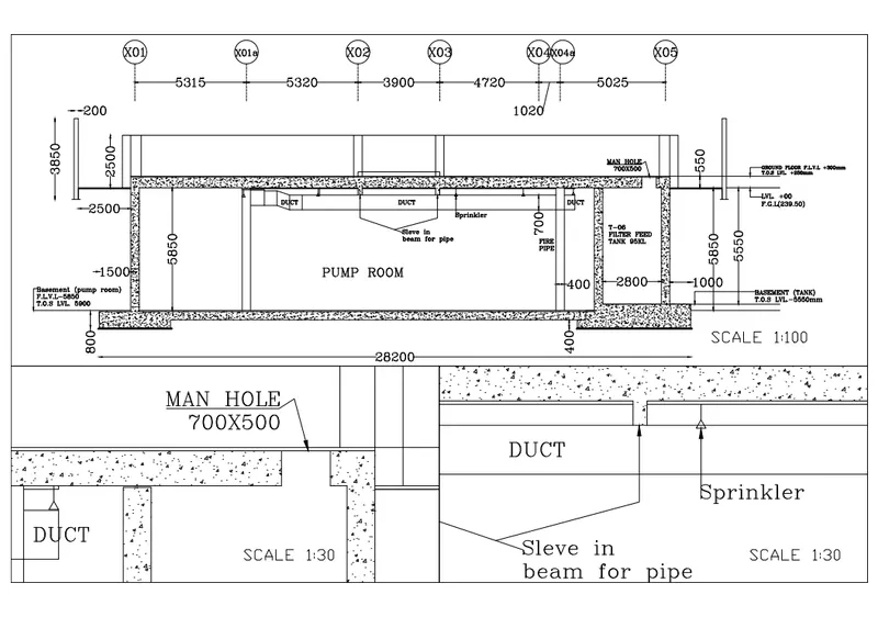
Creation of Multiple viewports, Scaling the drawing and setting in Template in AutoCad
Week 11 challenge report AutoCad
1.Aim is to create the layout of the Plan and Section A of the project in Challenge 7.
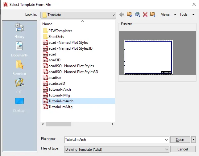
I am going to use the template Tutorial-mArch.dwt using scale 1:50.
I am going to use command MV Model Viewports to create the viewports of size 400x445 and 375x445.
I am going to use command ATTEDIT Attribute edit to edit the information in the title block.
The size of the Layout is going to be A1.
I am going to take a Plot in the end.
-
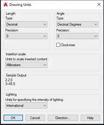
First step is to open a new page and set the Drawing Units as shown.
-
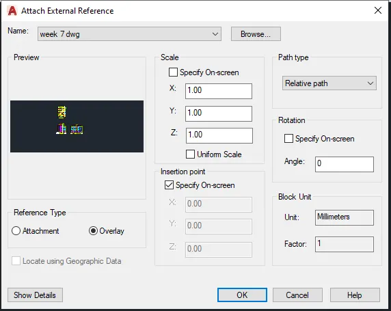
Next I use command: XREF to attach external reference : week 7 dwg.
-
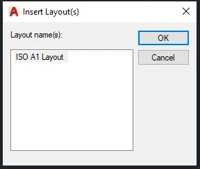
Type-LA for command layout> option Tamplete to add the tamplete Tutorial-mArch layout.
-
I rename the layout ISO A1 Layout as
plan and section chall.7
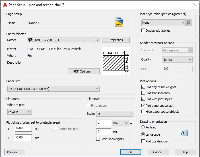
Then I go to page setup manager by right click to the layout name and do the chamges as shown.
-
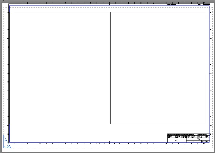
I create in the paper space two rectangles of dimensions 400x445 and 375x445mm.
-
Then I use command: MV Model Viewports> option object to turn the rectangles created into model spaces.
-
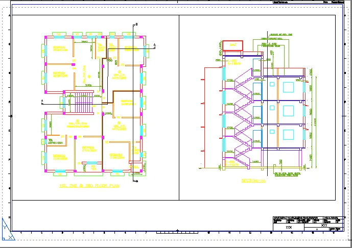
After working with the model spaces, adding the views with the scale 1:50 this is how the layout looks.
-
I use command MV Model Viewports> option Lock to lock the model viewports so I don’t change the scale by mistake.
-
Next I create a rectangle, which will give me the idea of the size of the text that I will add in the paper space. After dimensioning the hight of the text is going to be 1mm.
-
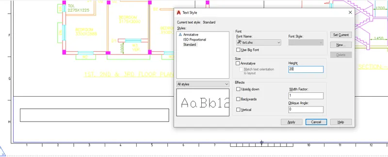
I type command ST for the style of the text and add the hight of the text 1 to the standart style .
-
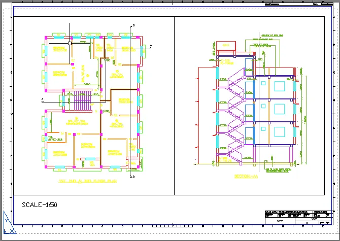
After working with the model spaces, adding the views with the scale 1:50 and adding the text as well this is how the layout looks before editing the attributes of the title block.
-
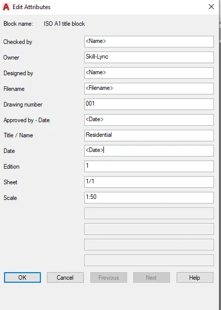
I use command: ATTEDIT> select block reference to edit the attributes of the title block.
-
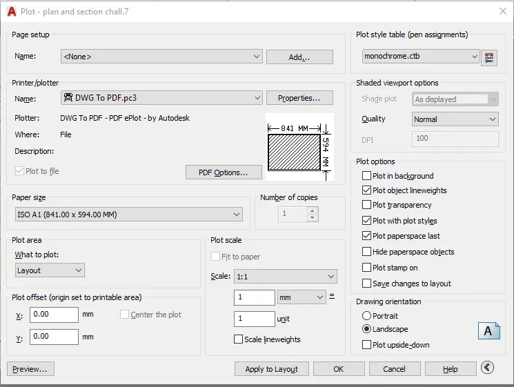
With right click to the name of the layout> Plot
this is the plot table
-
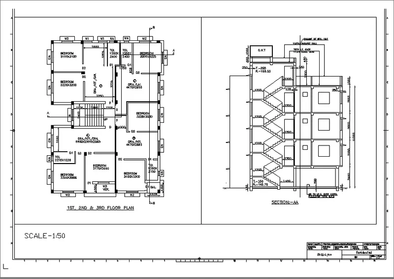
Presing the Preview.. option at the plot table
this is the preview of the layout.
-
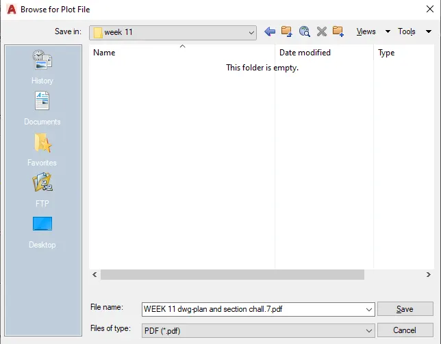
At the preview of the layout, I click right> option Plot to save the layout as a pdf file.
-
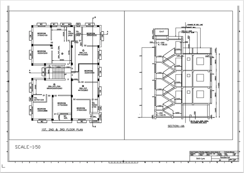
After ploting and saving the document this is the final pdf file of the plan and section AA of the week 7.
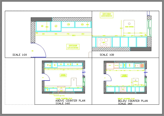
2.Aim is to create the Layout of the Kitchen Drawn in challenge 10 as shown in the figure. We will use different scales as shown and use a A4 size page for the layout.
-
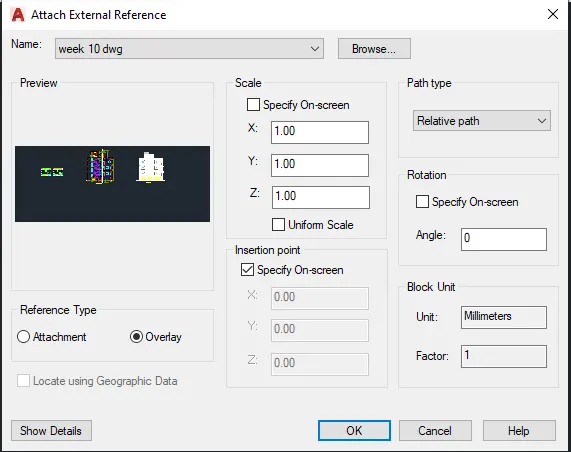
First step is to use command: XREF to attach external reference: week 10 dwg.
-
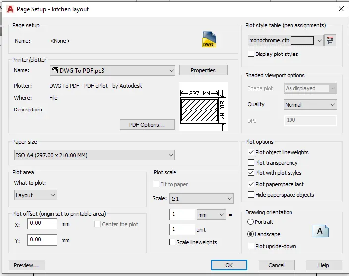
I rename the layout by doubleclicking at the layout name and doing the changes, and then Right click to the layout name > page setup manager and do the changes as shown.
-
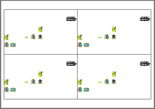
I use command Model Viewports MV > option 4> option fit to add 4 model spaces into the layout.
-
I try to add the views of the kitchen with the scale 1:1 as given but in a size A4 as required the scale dosn’t match with page size.
-
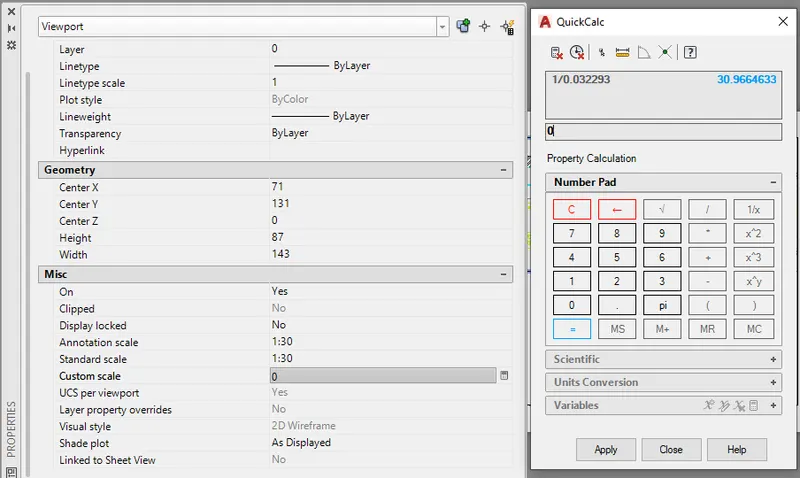
So I rightclick at the borders of the modelspace, go to properties and find the calculator at Custom scale. Before I have zoomed the view required and at the scale space is shown the value 0.032293.
-
To find the aproximate scale I do the follouing calculation 1/0.032293=30.9664633
-
This means that the aproximate percentage is 30% or scale 1:30.
-
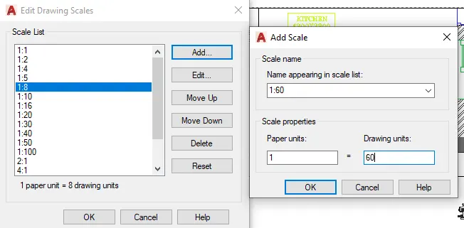
The same calculations I do for the above model viewports and the scale is 1:60 aproximatly.
-
I create a new scale 1:60 as shown.
-
After adding the views with the scales calculated I Lock them using command MV Model Viewports> option Lock.
-
With the command ST I add a text style style1 of height 3mm, and using command T for text I type the text as shown.
-
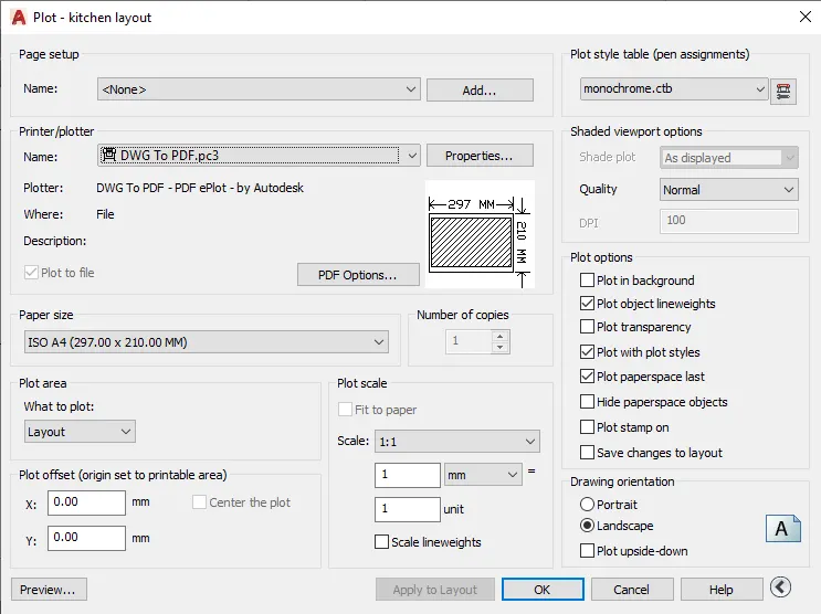
I rightclick at the layout name> option Plot
and this is the plot table.
-
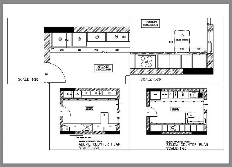
This is the preview of the layout.
-
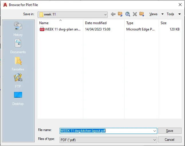
I rightclick at the preview > option Plot to save the pdf file.
-
This is the result of the PDF file of the kitchen layout.
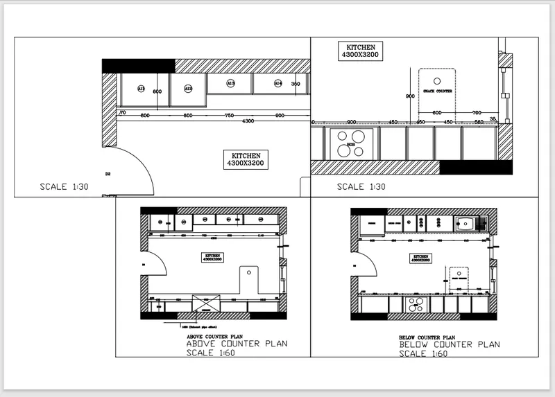
3.Aim is to create the layout of the section of the industrial building created in challenge 10.
I will use scale as shown in the figure and I am going to use MV Model Viewports Command to create 3 viewports.
In the end I am going to take a plot.
-
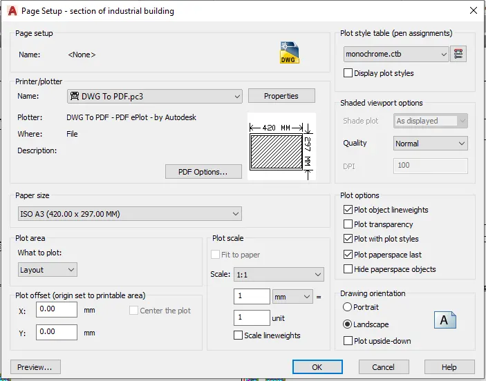
First step is I rename the layout, and with a right click at the name of the layout> option page setup manager I setup the size of the paper as shown.
-
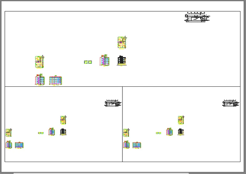
Next I use command MV>option 3> option Above> option Fit to ad 3 Model Viewports.
-
After working in the model spaces, adding the views with the given scales this is the layout before adding text into the paper space.
-
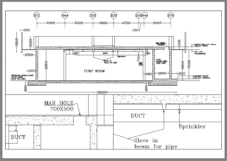
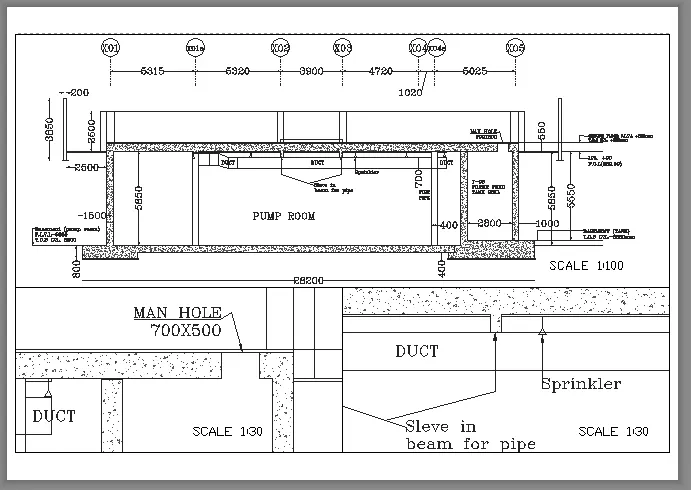
After adding the text using command T and using hight of the text 5mm this is the section of industrial building layout.
-
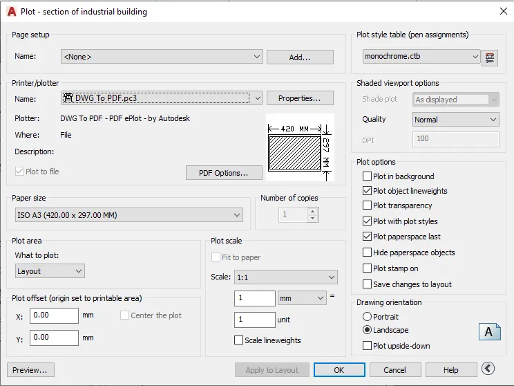
I click right at the layout name> option Plot and this is the Plot table.
-
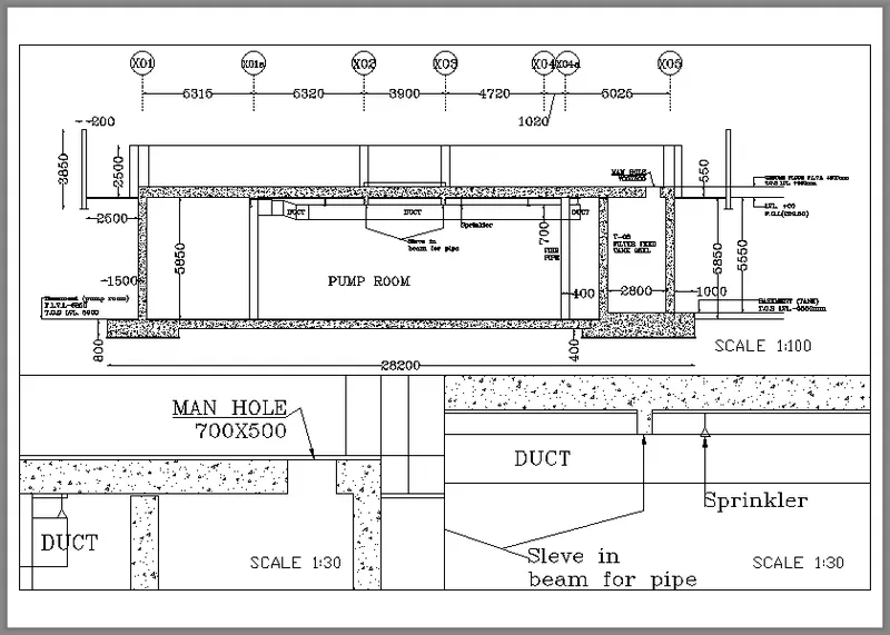
This is a preview of the pdf file.
-
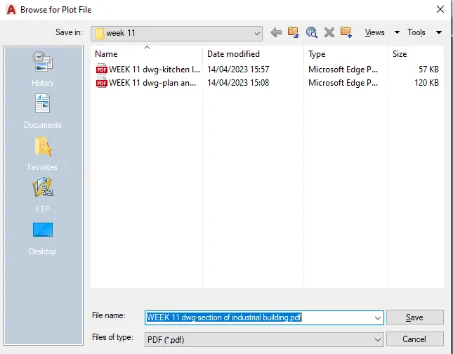
I click right> option Plot to save the pdf file.
-
This is the final view of the pdf file of the section of industrial building layout.