Creating Bar Bending schedule, Different Door types, and Creation of standard drawing templates using AutoCad
Week 9 challenge report Autocad.
1.AIM: Aim is to create the tampletes as shown in the figure. While creating the tampletes we need to add attributes as well (information in the tamplete which may change from time to time) and after create blocks out of these tampletes. We are going to create two blocks
Custom1_titleblock and Custom2_titleblock.
-
First step is to set the Units and Limits of the working space.
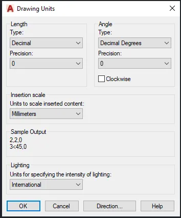
LIMMAX
Enter new value for LIMMAX <420.00,297.00>: 10000,10000
Command: ZOOM
Specify corner of window, enter a scale factor (nX or nXP), or
[All/Center/Dynamic/Extents/Previous/Scale/Window/Object] <real time>: A
Regenerating model.
-
To start creating the drawing of the first block Custom1_titleblock
First I open a Layout space, rename it A0, I right click to the layout name>Page Setap Manager>Modify> and choose from there
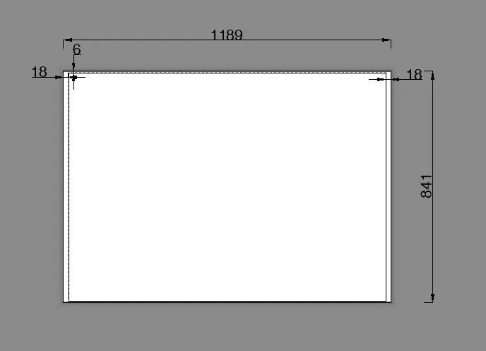
Paper size ISO A0 (841x1189mm)
In this way I make sure to know the right dimensions of the page where I am going to create the tamplete.
-
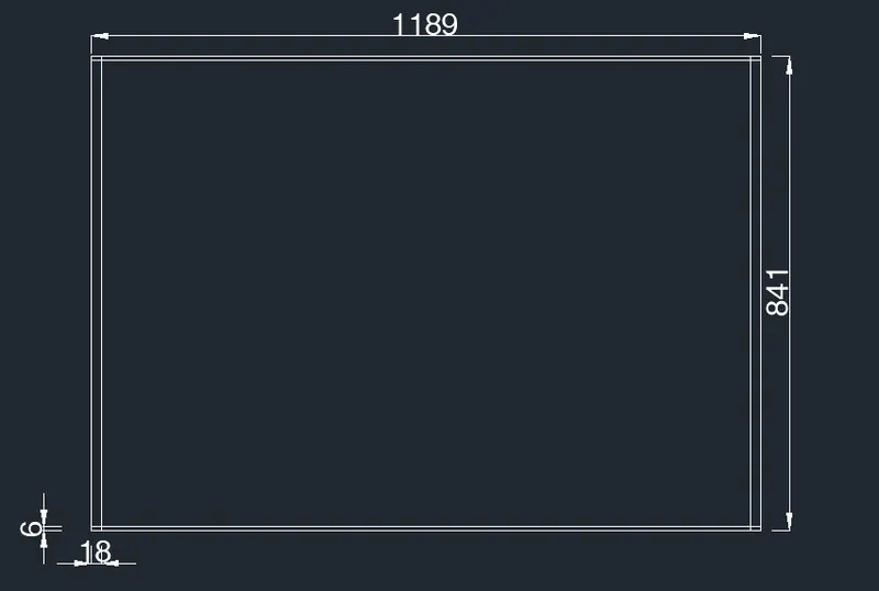
Now that I know the right dimensions, using command REC for rectangle I draw a rec as shown, then I explode it and offset it’s sides as shown and then I filet the corners to create the space where I ama going to create the tamplete of page A0.
-
Now using Command Line and Offset with the dimensions shown I start creating the table.
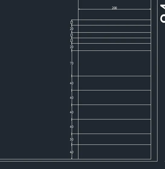
-
I create a text style named style6 of heigh 6mm.
I add all the text at the table as shown using command: Text
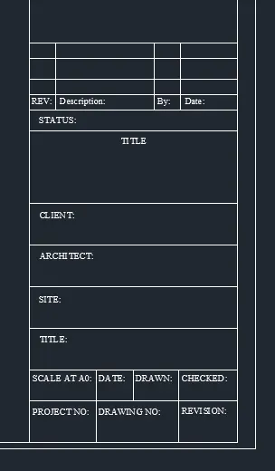
-
Now I add the atributes using command: ATT Attribute Definition.
I do the same step as in figure for all attributes that I am going to
add.
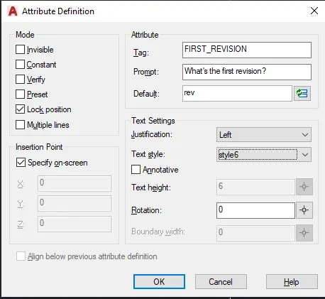
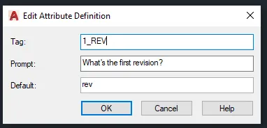
I change the name of the Tag because was to long.
-
This is the tamplete before turned into a block, containing the text and Tag of the attributes.
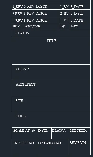
-
I use commannd: B for Block to create the first block
Custom1_titleblock
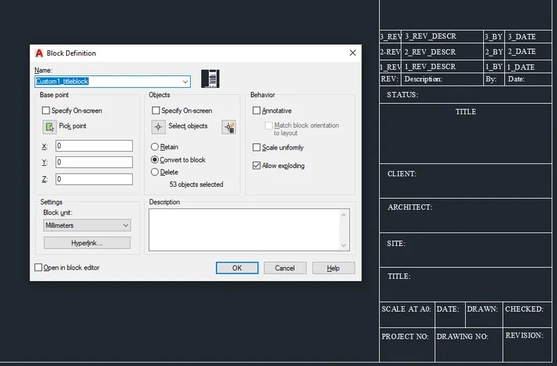
-
This are the attributes added to the block
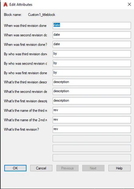
-
This is the created block Custom1_titleblock containing the table, the text and the default of the attributes.
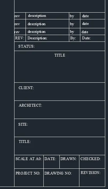
-
I follow the same steps to create the block Custom2_titleblock
First I open a Layout space, rename it A4, I right click to the layout name>Page Setap Manager>Modify> and choose from there
Paper size ISO A4 (297x210mm)
In this way I make sure to know the right dimensions of the page where I am going to create the tamplete.
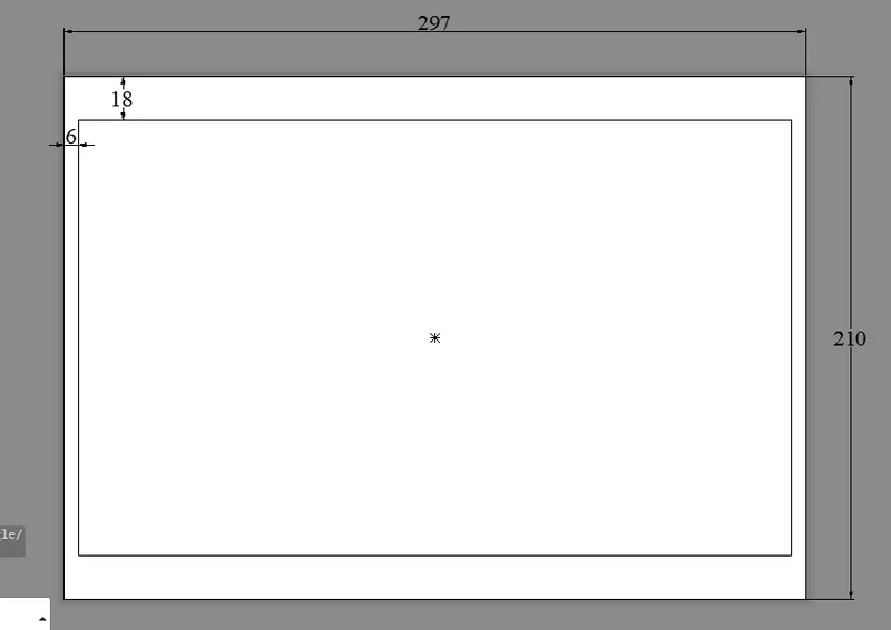
-
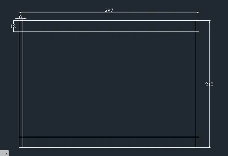
Now that I know the right dimensions, using command REC for rectangle I draw a rec as shown, then I explode it and offset it’s sides as shown and then I filet the corners to create the space where I am going to create the tamplete of page A4.
-
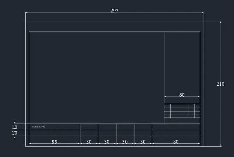
Using command: Line, offset I create the table with the offset values as shown.
-
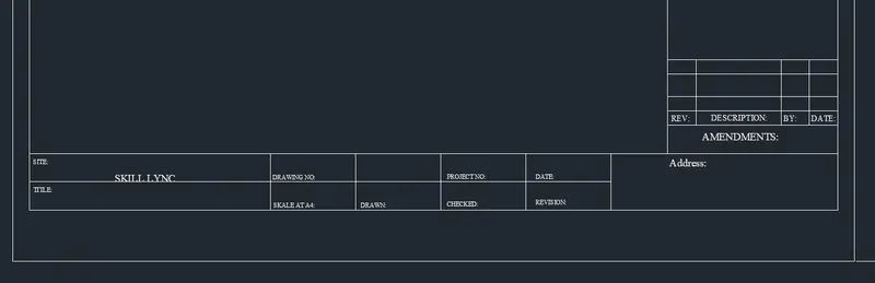
I create a text style named style7 of heigh 1.5mm.
I add all the text at the table as shown using command: Text
-
Now I add all the attributes one by one using command: ATT Attribute Definition.
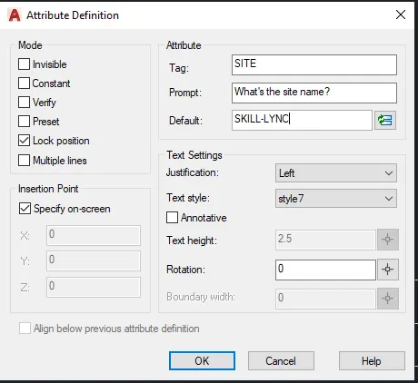
-
This is the table containing text and Tag of the attributes.
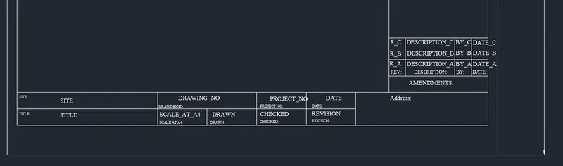
-
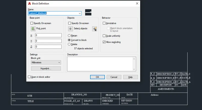
Using command: B for Block I create the block Custom2_titleblock
- These are the attributes added to the table.
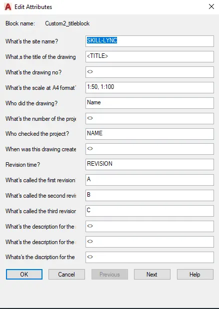
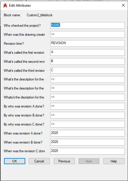
-
This is the block Custom2_titleblock created containing the table, the text and the default of the attributes.
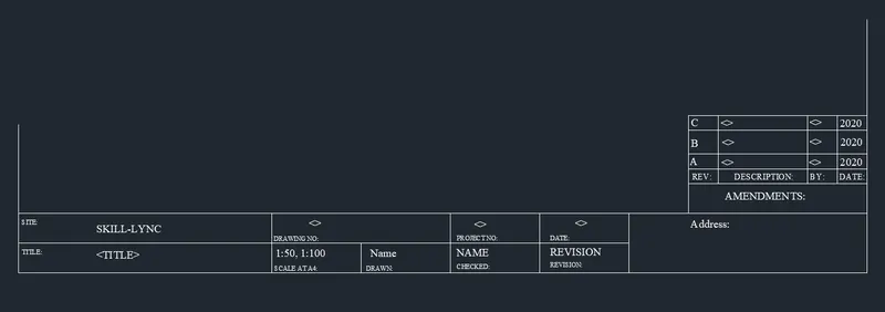
2.AIM: Aim is to create the doors type for warehouse as shown in the figure. After creating them, we need to turn them into blocks and name them as per given name in the picture.
-
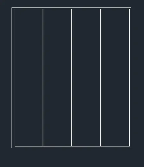
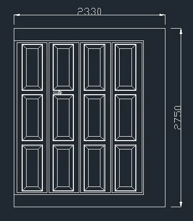
I start by creating one rectangular with dimensions: 2330x2750.
I offset it as shown in the figure.
-
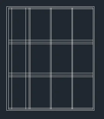
I offset it again to create the right shape inside the door.
-
This is the shape inside the door created.
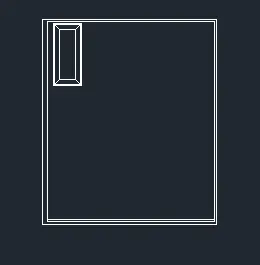
-
Then I use command: copy with option array and fit to place the shapes inside the door. Then I create the handle as well using commands rectang and fillet.
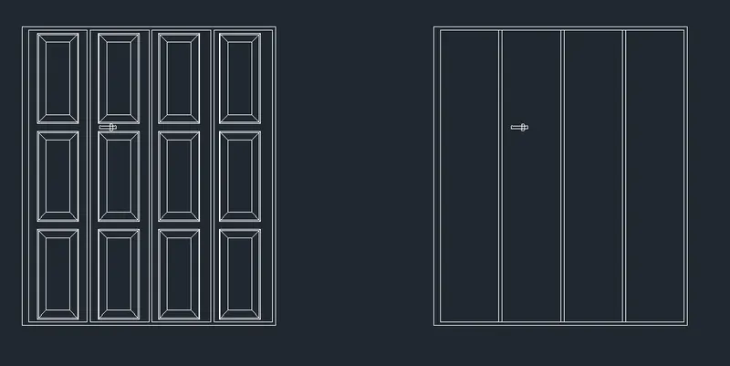
-
Here I realise thet I have drawn the picture wrong. To avoid drawing it from the beginning I scale the above pictures using option reference and from 2330 to 2000 values.
-
Then I draw a rectangular 2330x2750mm and I place the door element into this rectangular. The door 1 AND 2 is created.
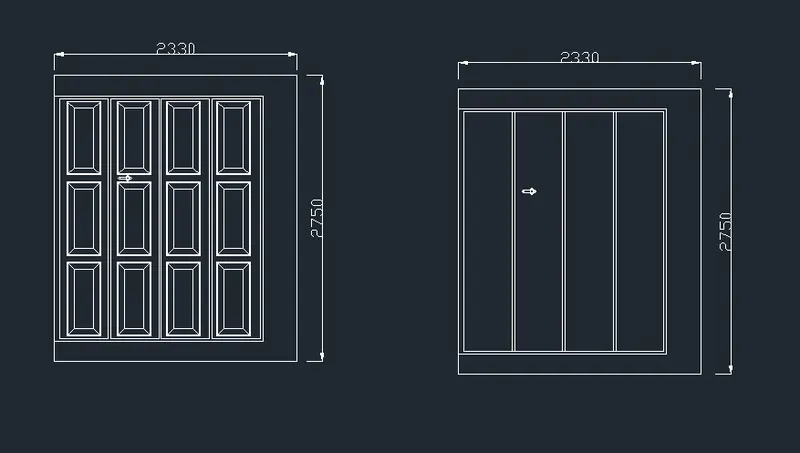
-
Using command: B for Block I create the block DOOR 1.
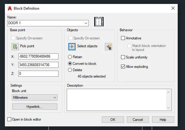
-
Using command: B for Block I create the block DOOR 2.

-
This are the blocks DOOR 1 and DOOR 2 created.
3.AIM: Aim is to create each simbol as a block with the name given in the legend. After to use command Insert to insert the blocks into the legend and command: Field to add the name of the blocks automatically in the legend, without the need to type the name again.
-
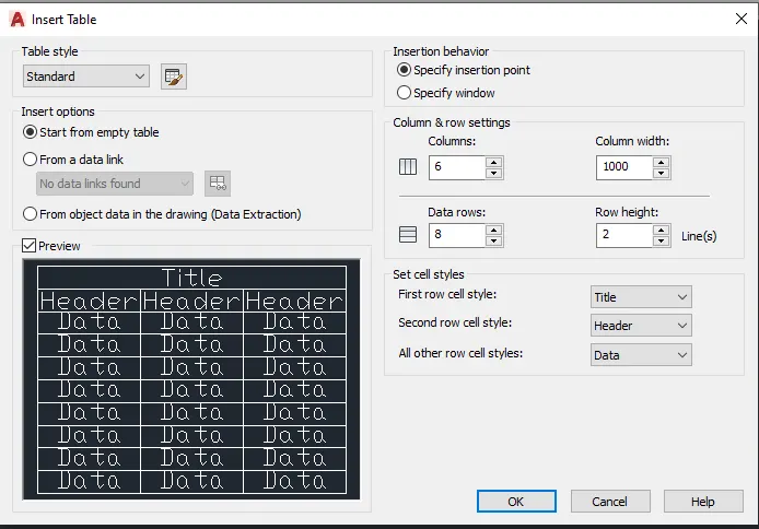
First I create the table of the legend using text style Standart with height 100mm.
-
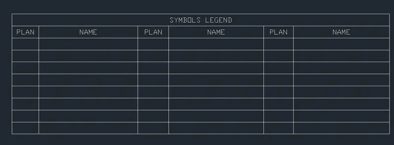
I type the title and headers of the legend as shown.
-
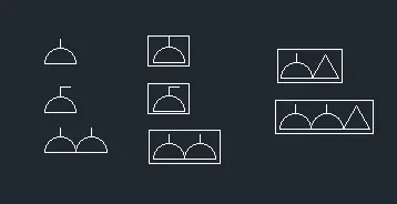
Now with command: circle, line, hatch, copy, arc, rec, polygon… I create the simbols one by one as shown.

-
I create a layer Text with lineweight 0.7mm, I create a text style style2 with height 60mm, and using the layer text and style2 text style I add the text inside the simbols.
-
I make sure the lineweight is displayed by typing command Lineweight clicking display lineweight.
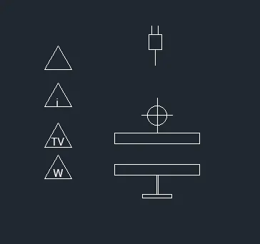
-
Now using command B for Block I create the blocks out of the elements and their particular names given in the legend.
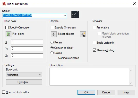
-
This are the blocks created.
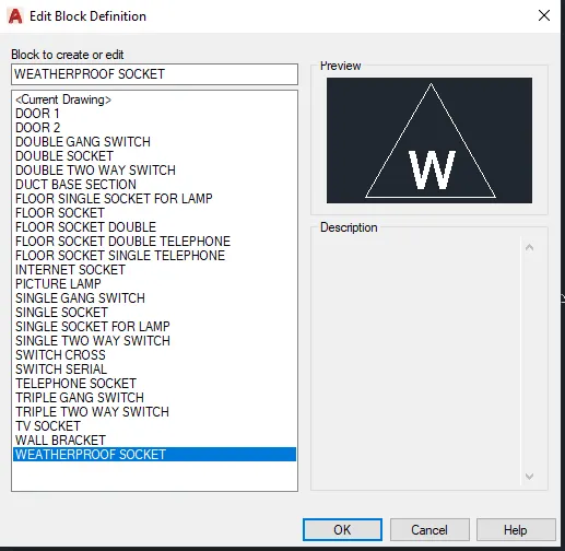
-
Using command: Insert I insert each block in their particular places in the legend.
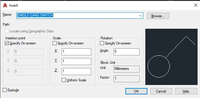
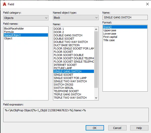
- On the side I use command Field to add automatically the particular name of each block.
-
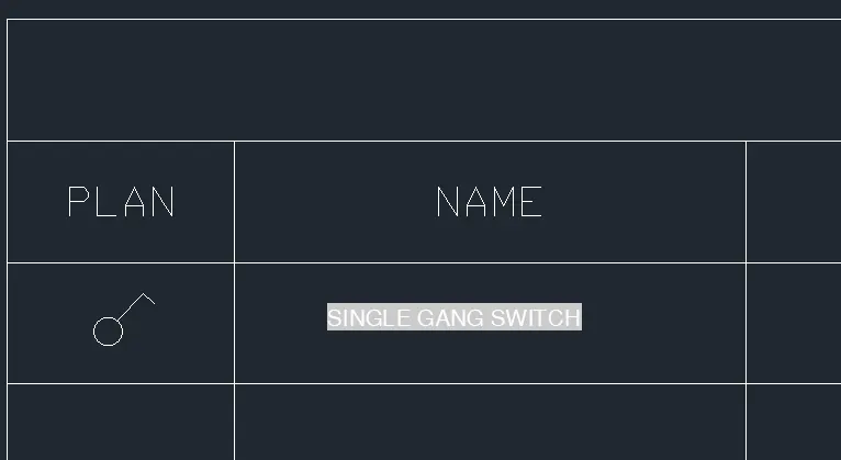
This is the simbol as a block and it’s particular name added with commands Insert and Field.
-
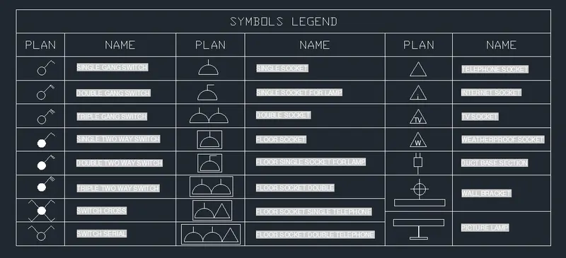
This is the legend created.
-
To remove the grey hilights we can explode the table, but since when printing the grey shade is invisible I didn’t explode it. Like this I can regenerate any change done in the future with the name of the blocks.
4.AIM: Aim is to create different doors of different sizes or shapes used in residential buildings and turning them into blocks.
-
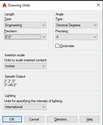
First open a new file and set the Units of the working space in inches.
-
Using commands: rectangle, offset, explode, trim, extend… I create door D1.
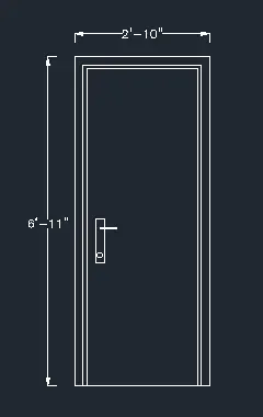
-
Using command B for Block I create first block D1(2’10’’X6’11’’)
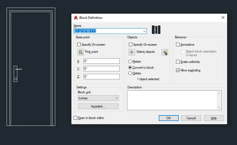
-
Using commands: rectangle, offset, explode, trim, extend, array, circle… I create door D2
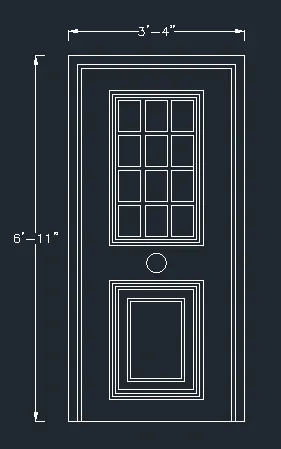
-
Using command B for Block I create first block D2(3’4’’X6’11’’)
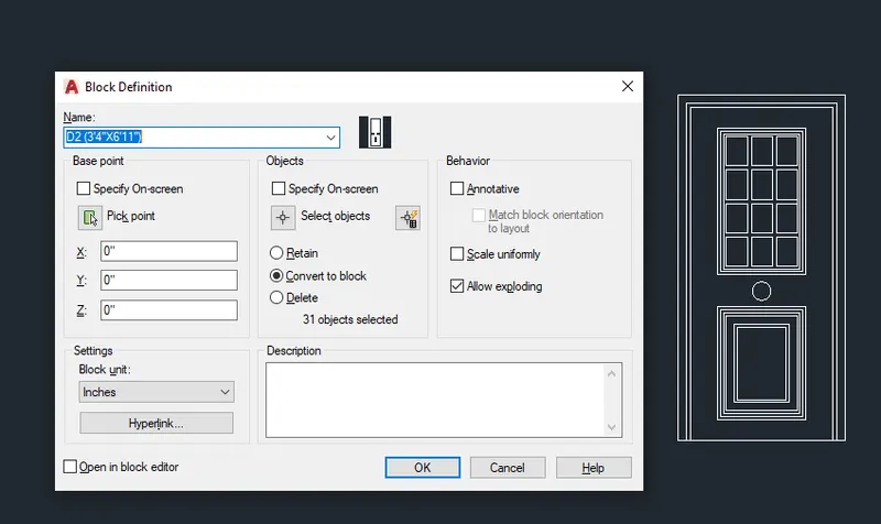
-
Using commands: rectangle, offset, explode, trim, extend, hatch… I create door D3
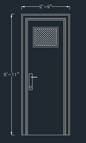
-
Using command B for Block I create first block D3(2’9’’X6’11’’)
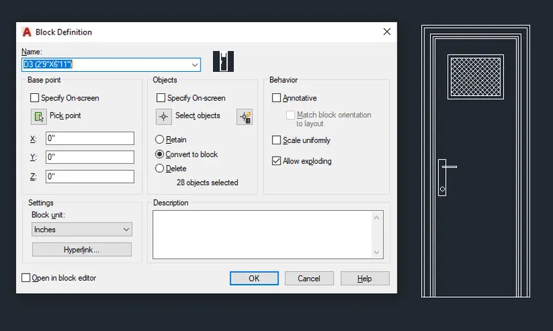
-
Now I copy door D2, I select and delete the unwanted lines, using command Array I add the rectangles in the bottom side of the door and door D5 is created.
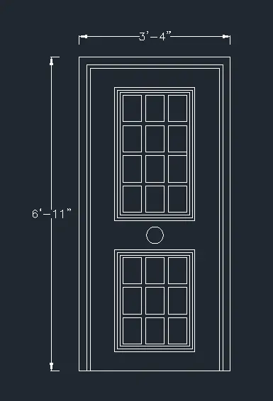
-
Using command B for Block I create first block D5(3’4’’X6’11’’)
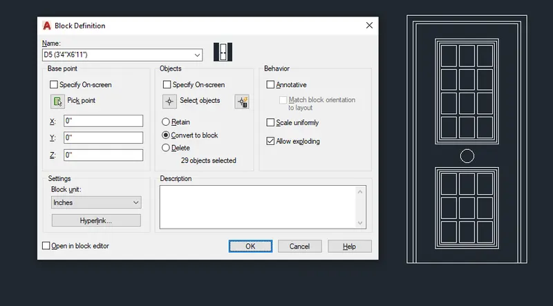
-
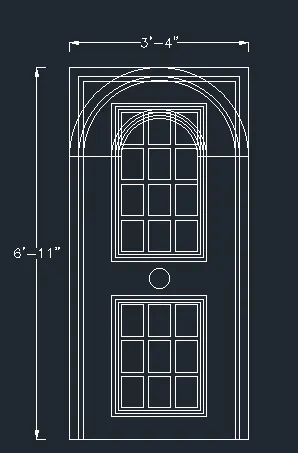
I copy door D5, explode it, using command arc start,end angle -180 degree I draw all the arcs as shown.
-
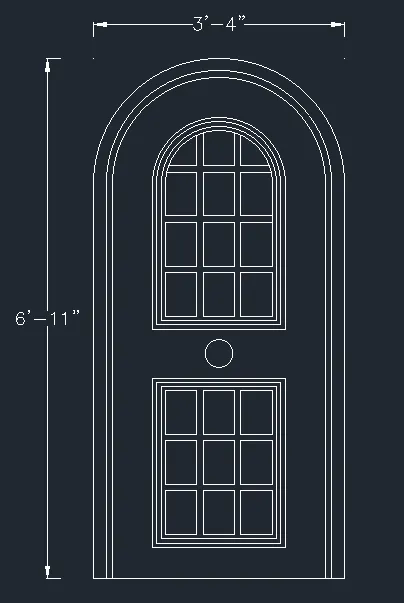
Using command trim I trim the unwanted parts and this is door D4 created.
-
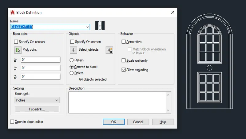
Using command B for Block I create first block D4(3’4’’X6’11’’)
-
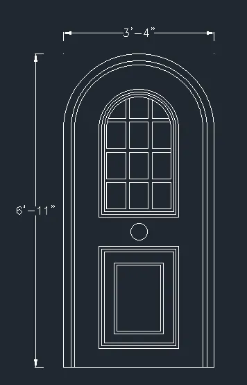
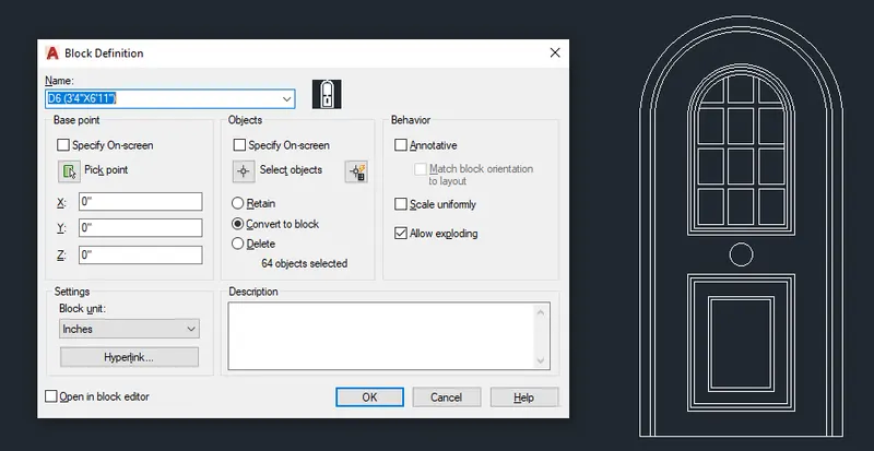
I copy door D4, explode it, select and delete bottom array and copy the middle lines from door D5 and add them at the bottom of the door as shown and that is the door D6 created.
-
Using command B for Block I create first block D6(3’4’’X6’11’’)
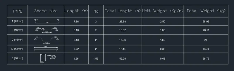
5.AIM: Aim is to create the bar bending schedule out of bar bending blocks and text as shown in the figure. Important is to create the bar bending shapes, then turn them into blocks, and insert them in the table respectivly.
-
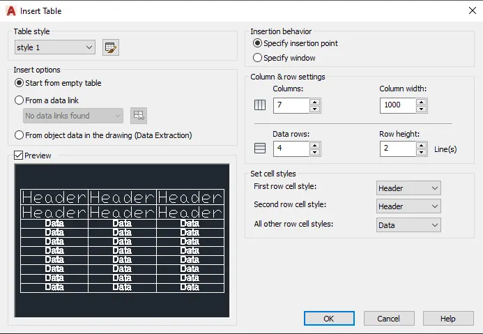
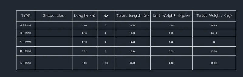
First step is to create the table of the bar bending schedule.
-
For this table I use text style2 of height 60mm.
-
This is the table with the text.
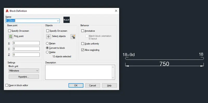
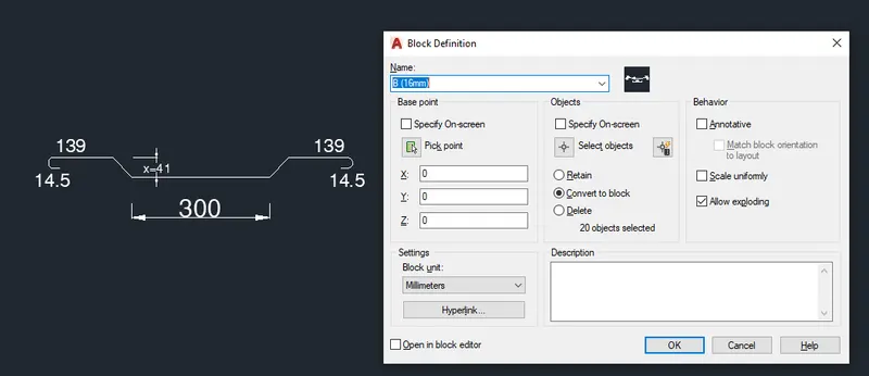
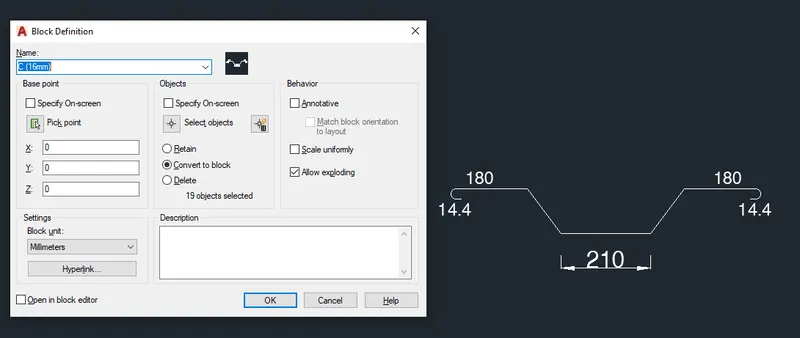
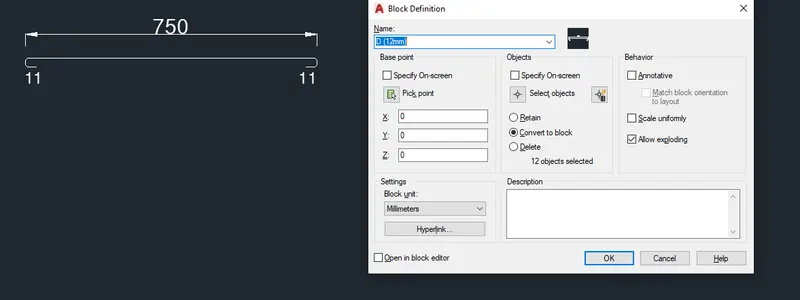
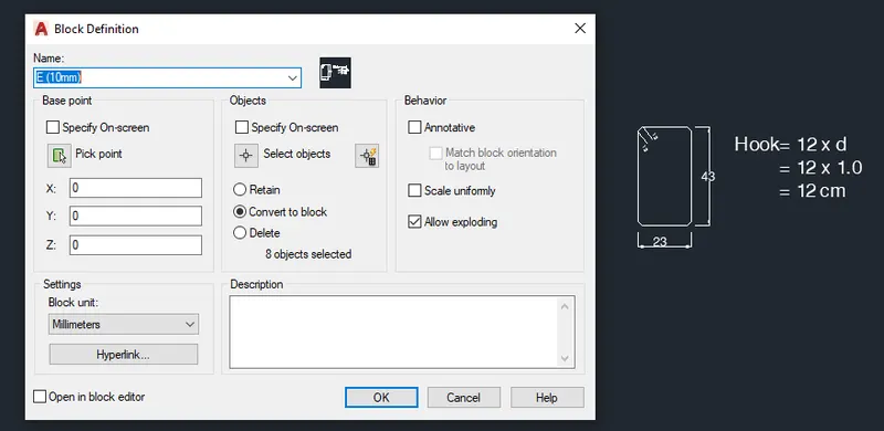
- Now I draw the bar bending shapes one by one and with command: B for block I turn them into blocks with their respective names.
-
Using command: Insert I insert each block at their places and the bar bending schedule is created.