Creating various 3D Models like Furniture, Footing, Girder, Column drop with panel and Gable Wall in AutoCad
QUESTION:
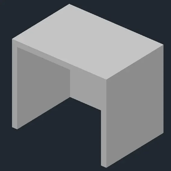
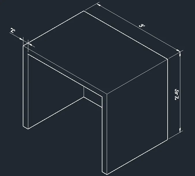
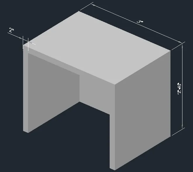
1. Create a 3D Furniture element as shown in the Figure. Assume dimensions which are missing.
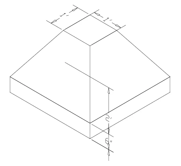
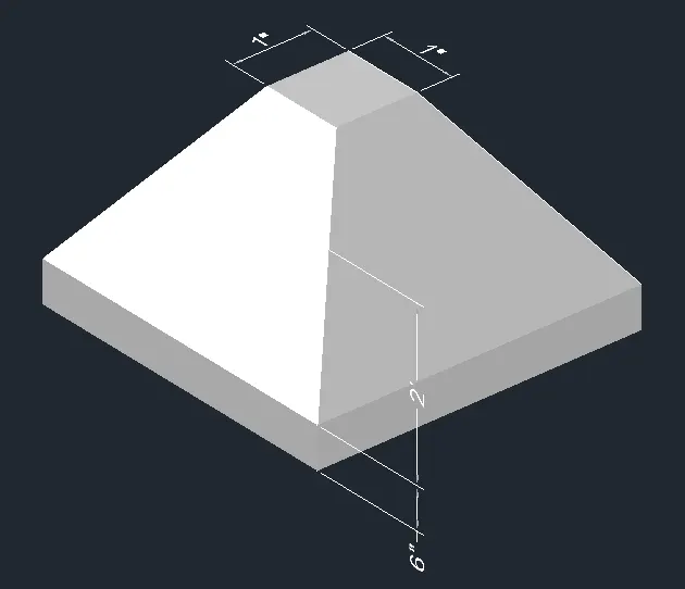
2. Create the 3d Model of an Isolated footing as shown in Figure.
3. Create the 3D view of the AASTHO Type Girder.
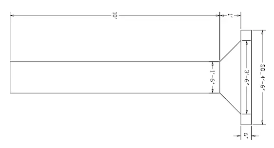
4. Create a 3d Model of a drop column with panel as shown in section and isometric view.
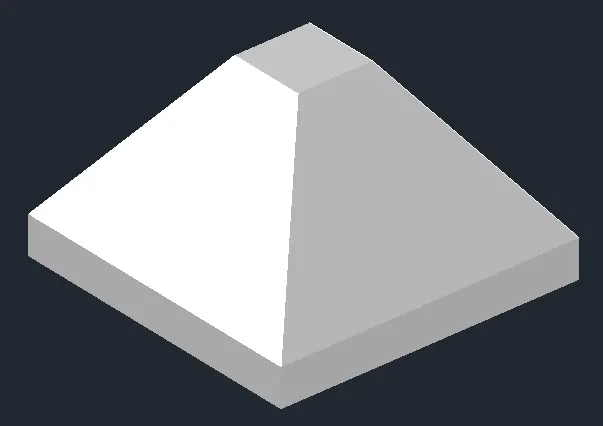
5. Create the 3d model of a wall as shown in Figure. Consider wall thickness as 9”.
AIM:
- To create a 3d furniture element
- To create the 3d model of an isolated footing
- To create the 3d view of the AASTHO type grider
- To create a 3d model of a drop column with panel
- To create the 3d model of a wall
INTRODUCTION:
AutoCAD 3D is a three dimensional computer aided design, is technology for design and technical documentation, which replaces manual drafting with an automated process
Types of 3D models,
- Wireframe models
- Surface models
- Solid models
Procedure:
Starting a AutoCAD software:
- Open Autocad software and click on START DRAWING.
- Set the units and length type by using 'UNITS' command.
- Set the limits by using 'LIMITS' command.
- Using 'ZOOM' command and select 'All' option
- Switch to 3D modelling on workspace.
- Use different tools and commands to create a given drawing.
- The above procedure use to given every drawings.
1. Create a 3D Furniture element as shown in the Figure. Assume dimensions which are missing:
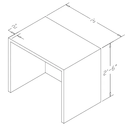
Step 1:
- Start a new layout and set the limits, units
- Change the workspace to 3D modelling option
- Create the line using LINE command length 3' and 2'2"
- EXTRUDE the created rectangle at a height 2'6"
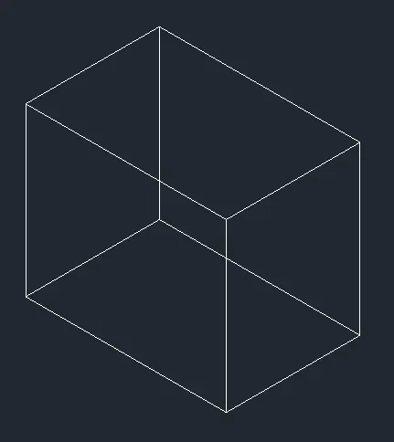
Step 2:
- Change the UCS to drafted direction
- Create a line 2" at a distance
- Create the rectangle an above the 2" line
- Extrude that rectangle 2'
- SUBTRACT option to use subtract the inner shell
- Make the dimensions at given figure
RESULT:
2. Create the 3d Model of an Isolated footing as shown in Figure:
Step 1:
- Start a new layout and set the limits, units
- Change the workspace to 3D modelling option
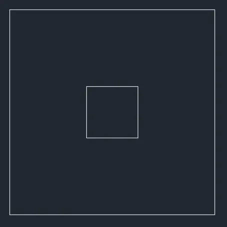
- First create a rectangle length 4' and width 4'
- Then create a another rectangle at length 1' and width 1'
Step 2:
- Change the UCS to convenience workspace
- Move the center rectangle at a height 2'
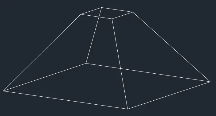
- EXTRUDE the below rectangle at 6"
- Mark the dimension from given diagram
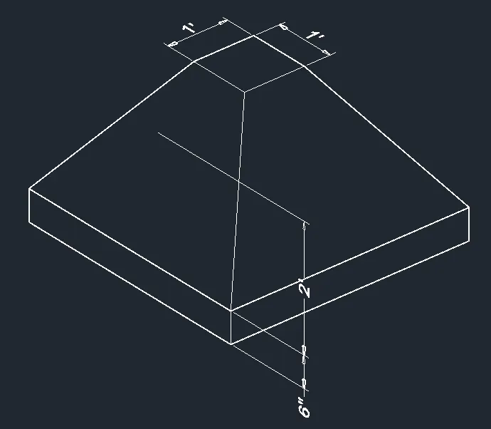
Result:
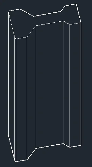
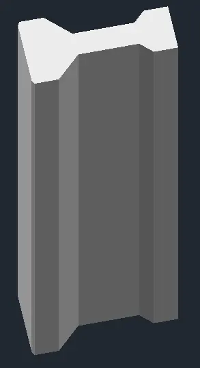
3. Create the 3D view of the AASTHO Type Girder
Step 1:
- Start a new layout and set the limits, units
- Change the workspace to 3D modelling option
- Create the diagram at agiven dimension
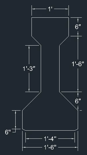
- Make it EXTRUDE at 10'
Result:
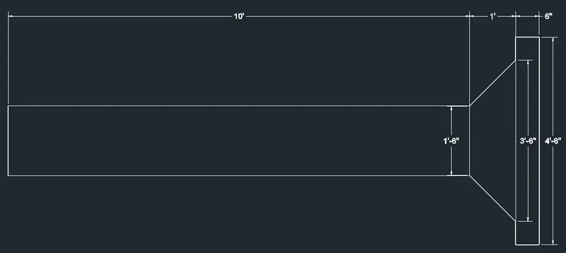
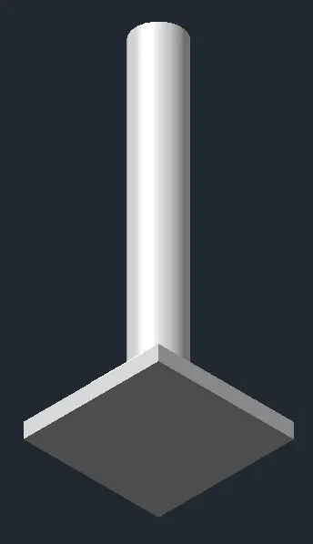
4. Create a 3d Model of a drop column with panel as shown in section and isometric view:
Step 1:
- Start a new layout and set the limits, units
- Change the workspace to 3D modelling option
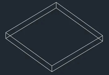
- Create a rectangle at given dimension
- EXTRUDE 6" at upwards
- Create the circle 3'6" and 1'6"
- Extrude the circle 1'6" in 10' length
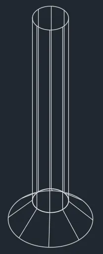
- Mark the dimension at a given diagram
Result:
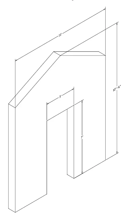
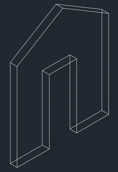
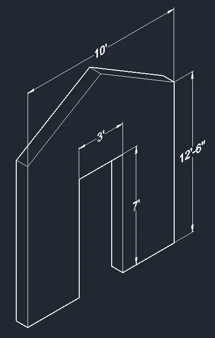
5. Create the 3d model of a wall as shown in Figure. Consider wall thickness as 9”:
Step 1:
- Start a new layout and set the limits, units
- Change the workspace to 3D modelling option
- Create a line at a given dimensional diagram
- And the wall thickness is 9"
- The created line can be EXTRUDE at 9"
- Mark the given dimension
Result:
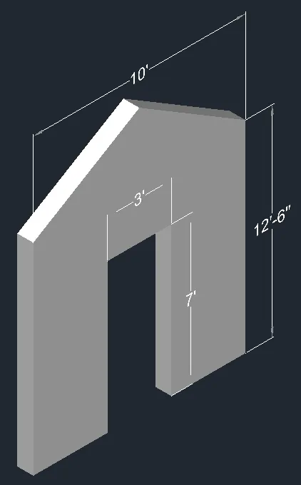
FINAL RESULT:
- The given 3D drawings are successfully drafted using AutoCAD
- All the final diagrams are attached below