Project 1 _Creating an Architectural plan for the provided plot size and develop relevant basic structural drawings
INTRODUCTION:- This project deals with AUTOCAD software which is widely used for drafting the plans, elevations, and all other required drawings for the execution of the work using various commands.
AIM:-
- to draw the floor plan of the given plot size of 60' x 20' facing east
- to draw elevation, sections of the plan
- to draw the structural plans like column layout, footing layout, and beam layout required for the site engineer to execute the work
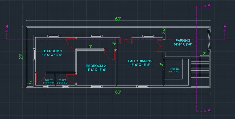
To draw the floor plan for the given plot size
- take a rectangle command
- specify the first point
- specify the next point as (60', 20')
- then take an offset of 4.5" to provide a compound wall
- then take an offset to provide setback of 2' on the west and 2'-6" on the north
- then provide an external wall of width 9"
- then provide the internal walls of width 4.5" for the partition of rooms
- in this project, I have constructed 2 bedrooms, 1 hall/dining, kitchen, and left space for the parking purpose
- then construct a staircase with a width of 3' and a landing of width 3'
- then provide openings for the ventilation and doors
- kitchen platform is provided with a width of 2'
- then add text and name the rooms specifying the dimensions of the room
- then show a section lines AA, BB for which the elevation should be drawn
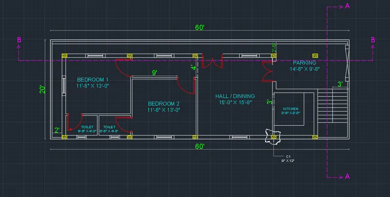
- add the columns to the plan
- take a rectangle command
- specify the first point
- specify the next point as 9" x 12" (column size)
- hatch the rectangle as concrete and create a block using the block command
- then select the block
- select the base point
- specify the next point and copy the column as required
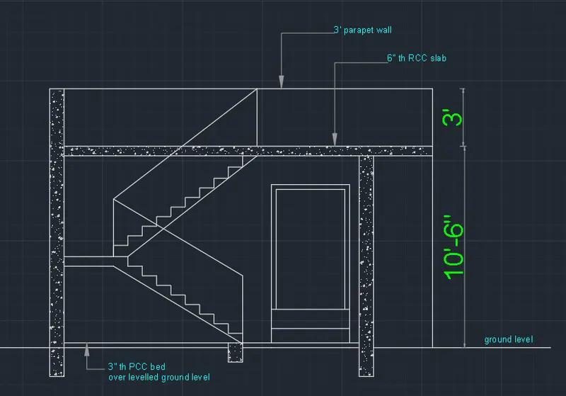
AIM:- to draw elevation of the section AA
- take a line command
- draw the lines joining the section points of the plan
- then draw a horizontal line
- take an offset of 3' to show the level of the PCC bed
- then take an offset of 10'6" to show the floor height
- then take an offset of 6" to represent the thickness of the RCC slab
- then construct the section view of the staircase
- the tread is taken as 9"
- riser is taken as 6"
- the thickness of the waist slab is taken as 6"
- height of the parapet wall is taken as 3'
- show the elevation of the entrance door
- height of the door is taken as 6'6"
- width of the door is taken as 3'6"
- 2 steps of length 3'6" and riser of 6" are provided at the entrance to coverup the level difference of the ground level and plinth level
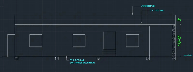
AIM:- to draw the elevation of section BB
- take a line command
- draw the lines joining the corner points of the plan in the section
- take a horizontal line
- take an offset of 3" to show the thickness of the PCC Bed
- take an offset of 10'6" to represent the floor height
- take an offset of 6" to represent the thickness of the RCC slab
- then take an offset of 3' to show the height of the parapet wall
- then draw the elevation of the windows
- windows are provided at the sill level of 3'
- size of the windows is taken as 4' x 4'
- elevation of the door (on the north face) is also drawn
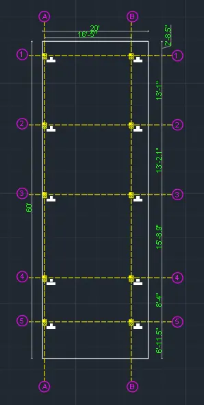
AIM:- to draw the column layout
- firstly select all the columns from the plans
- copy the columns on the other drawing area
- then draw the boundary of the plot
- draw the grid lines at the distance of 4.5" from the face of the column
- draw the horizontal and vertical grid lines
- name the vertical grid lines and horizontal grid lines
- take a command dim linear
- select the point and mention the dimension between the grid lines
- name the column as C1
- mention the column size as 9" x 12"
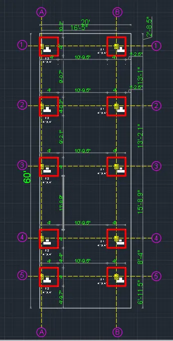
AIM:- To draw footing layout for the columns
- take a copy command
- select the column layout
- select the base point
- and copy the column
- draw the footing of size 4' x 4'
- footing should be placed such that the center of the column and center of the footing should match
- name the footing and mention the dimension
- then take a dim linear command
- specify the dimension between the footings
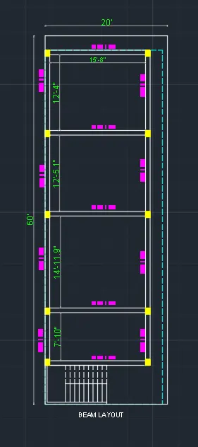
AIM:- to draw the slab beam layout
- select the columns and the slab line from the plan
- copy the columns and the slab line on the other space of the drawing area
- draw the beams connecting the columns in the horizontal and vertical direction
- size of the beam is taken as 9" x 12"
- take a dim linear command
- specify the length of the beams
- and draw the cross-section of the beam