Project 1 _Creating an Architectural plan for the provided plot size and develop relevant basic structural drawings
AIM- Design and Draft a layout of a residential building with the following details:
a. Plot size: 60'x20'
b. Orientation - East facing
c. Develop the following
i. Architectural Drawing( Floor plan , Elevation , Sections)
ii. Structural Drawing( Column , Beam ,and footing layout)
PROCEDURE -
All the necessary settings and units are made as of the requirement
The limits are also set according to the drawing
All the layers are created like walls columns windows doors etc with specific colour to it
STEP 1: Architectural Drawing
I. External walls
To create layer , in the layer properties manager , click new layer and enter the name as wall and given a specific colour for that
Now the wall layer is set as a current layer and by using line , offset , trim and fillet tool the external walls are drafted as per the dimensions
II. Internal walls
The internal walls was also given the same layer as that of external walls
All the internal walls are drafted as per the dimensions
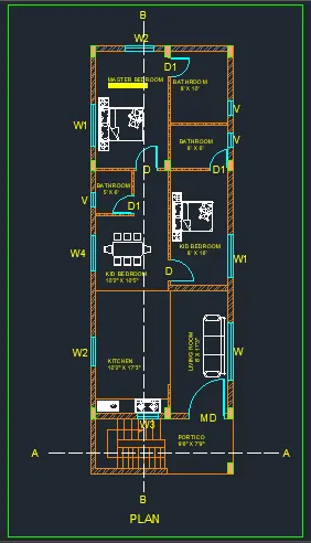
A hall of size 8' x 17'3" was drawn followed by the rooms and others parts of the building as follows
Toilet - 5' x6'
Master toilet - 10'x8'
Master bedroom - 10'2' x 16'5"
Kitchen cum dining - 10'2" x 17'3"
III. Staircase and steps
A new layer is created in the name of staircase and a specific colour is given to that
Now this layer is set as a current layer and started dtafting staircase and steps with a stair width of 3' and rise of 6'' and thread of 1'
IV. Doors and Windows
A new layer is now created , named as doors and windows and a suitable colour is applied to it
Now, this layer is set as current layer and started drafting windows and doors as per the dimension.
Door and Window provisions are as follows
MD - 5' X 7'
D - 3' X 7'
D1 - 2.5' X7'
W- 8' X 7'
W1 - 6' X7'
W2 - 4' X 4'
W3 - 3' X 4'
W4 - 5' X 4'
V- 2'X1.5'
V . Blocks
A new layer is now created and named as block and a specific colour is given to it.
Now , this layer is set as current and all the necessary blocks are inserted to the floor plan
Pre - existing block drawing of wash basin , dining table , and closet blocks was placed at the correct places and the following image is obtained
VI. Dimension
A new layer is created and name as a dimension
Now this layer is set as current and all the dimension are given to the plan using Dimlin , and Dimcont command
VII. Texts
A new layer is created and named as a texts and specific colour is given to it
Now this layer is set as current and all the necessary texts are given to the plan using Mtext command
Now the Floor plan is drafted using Autocad tools and the final image is obtained
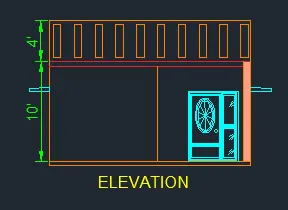
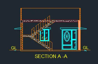
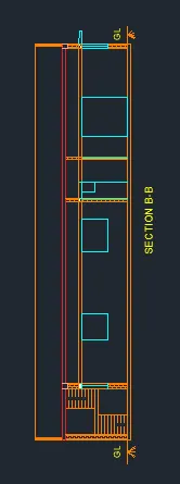
Elevation and Section
By using constrction lines all the walls and necessary opening are projected to draw the elevation and sections
By using trim tools all the extra projection are trimmed as per the requirement
By using hatching tool all the necessary hatchings are provided to the drawing
A parapet wall of 4' is also drawn
Doors and window projections are drafted in the levation and plans
All the necessary dimension and texts are also provided
Then the final image is obtained
2 . Strctural drawings
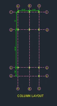
I. Coloumn layout
Turnoff all the layers except columns and centre line
Use copy command to copy the columns and set the centre line as a current and started drawing centre lines to the columns
Numbering is given to the centre line of the column with numner , alphabet and circle around it
Turn on the dimension layer and give dimension to the drawing
Now ,the final image is obatined
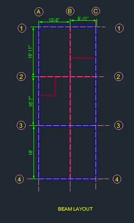
II. Beam layout
Turn off all the layers except columns, beams , centreline and walls
Use copy command and select all the columns and move them to a different position
Join all the columns with line command for representing beams
The primary beams which connect from column to column is now completed
Secondary beams are beamns which connects from the primary beam
All the internal walls are connected to primary beams
Numbering is given to the each centre line
Dimension are given to the drawing
Now , the final image is obtained
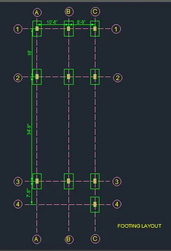
III. Footing layout
Use copy command and select column layout drawing and move it to some location
Select the layer " centre line"
By using line command all the centre lines are given
Isolated footing of size 3' x5' is drawn by using rectangle command
After the footing is cdrawn all the necessary dimensions are gievn to the drawing
Now the final footing layout is completed
RESULT - All the Architectural drawing and structural drawing of the house in the plot of 60'x20' east facing is drafted.