Creating Bar Bending schedule, Different Door types, and Creation of standard drawing templates using AutoCad
AIM- Creating Bar Bending schedule, different Door types , and creation of standard drawing templates using Autocad.
INTRODUCTION- The main objective of this study is know more about the advanced tools in AutoCad by drafting different kinds of drawings given.
Q.1 Create the templates as shown in Figures. Take the size of the title block as per industry standards or you can assume it as per the size of the paper. Use text and attributes wherever required. After creating the title block you need to save it as a block with names: Custom1_titleblock and Custom2_titleblock, respectively.
Procedure-
Step-1 Custom1_titleblock
A new layer is created in the name of Table and make it as current layer with suitable colour assigned to it.
A table is created with tthe help of table tool or even by rectangle line and offset tool.
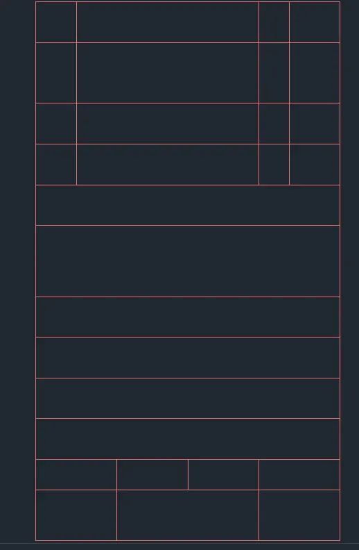
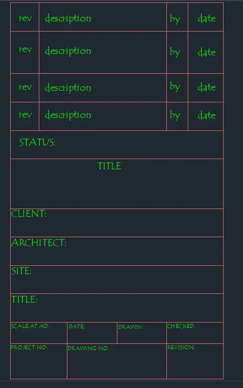
Again a new layer is craeted in the name of texts with suitable colour assigned to it and make its as current . Type ST to open text style manager and change the font to TEMPUS SANS ITC and required height is also set and make it as current.
Now using the sinle line text all the text was entered at the possition as per the requirement .
Step 2- Custom2_titleblock
A new layer is created in the name of Table and make it as current layer with suitable colour assigned to it.
A table is created with tthe help of table tool or even by rectangle line and offset tool.
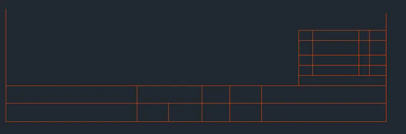
The text layer which was created is made as a default layer. Now using the sinle line text all the text was entered at the possition as per the requirement .
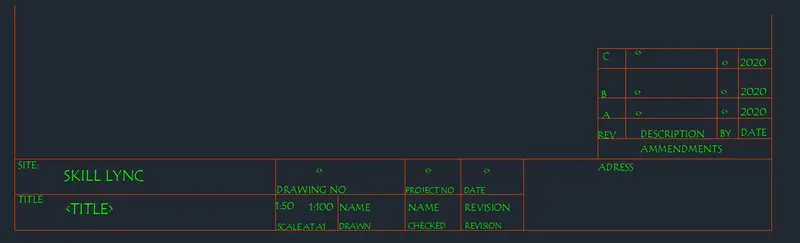
RESULT - The standard template is created and converted as a block using AutoCad tool.
Q.2 Create the doors type for warehouse as shown in the Figure. You need to create each door type as per standard size or given dimensions. Create the blocks of this door type after creating them.
PROCEDURE-
Step-1
In the layer properties manager, click new layer.
A layer name is added to the layer list. Enter a new layer name as Door frame by typing over the highlighted layer name with suitable colour assigned to it.
Using the line command , offset , trim , extend , fillet command and the dimension given in the figure following portion of door was created.
A new layer is now created , named as panels and suitable colour is selected and this layer is made as the default.
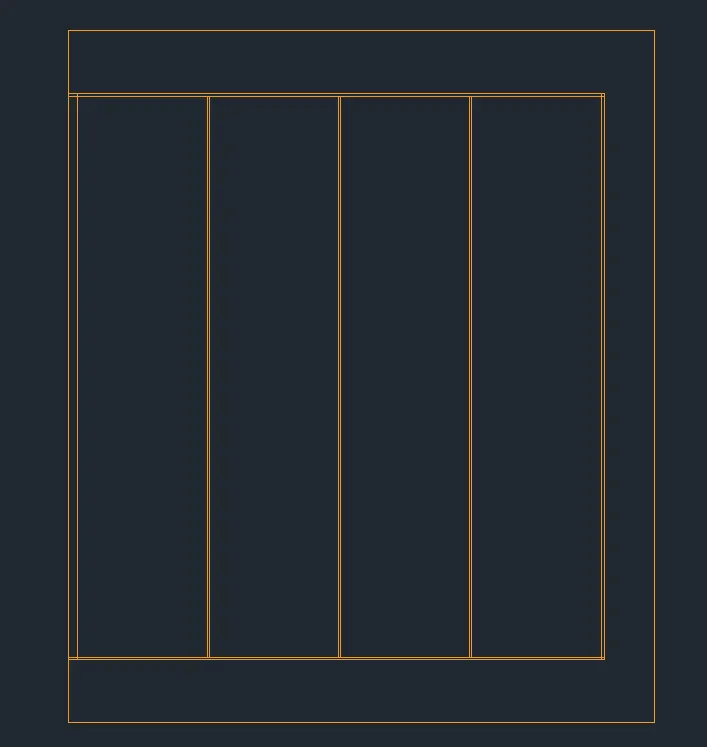
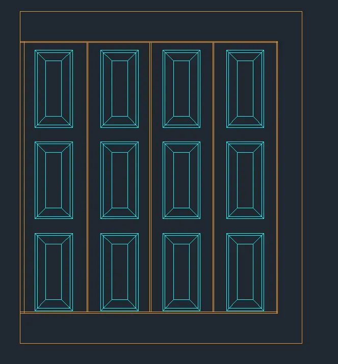
Using rec command a rectangle of size 310x640mm was created.This rectangle was offsetted to the inside by 20 and 70mm respectively.The corners of all the recatangle was joined using a line.
Select rectangluar array from the ribbon panel , select the object and enter the number of rows and column required with spacing and enter.
The handle of the door was created using the line command.
A new layer is created for dimension with suitable colour assigned to it and made it as default.
Now using Dimlin command the dimension is assigned to the drawing.
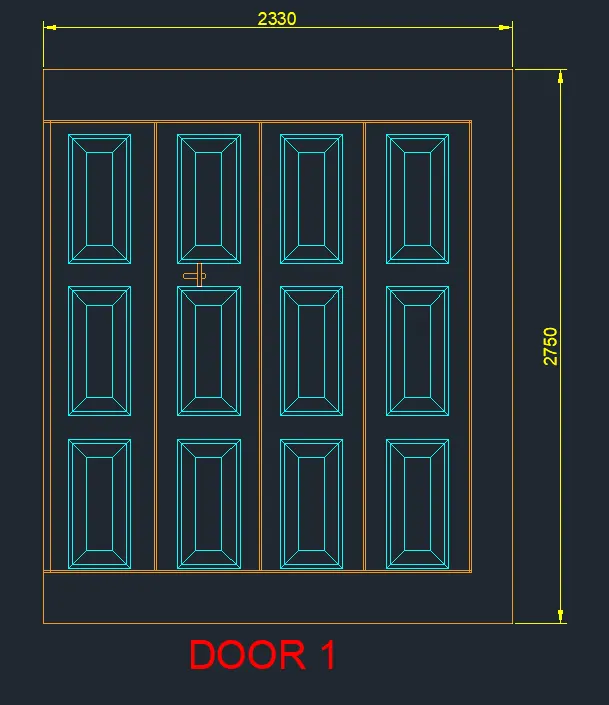
Step-2
The door layer which was created is made as default layer.
Using the line, offset, trim , extend , fillet command and the dimesnion given in the figure the following portion of door was created.
The handle of the door was created using the line command.
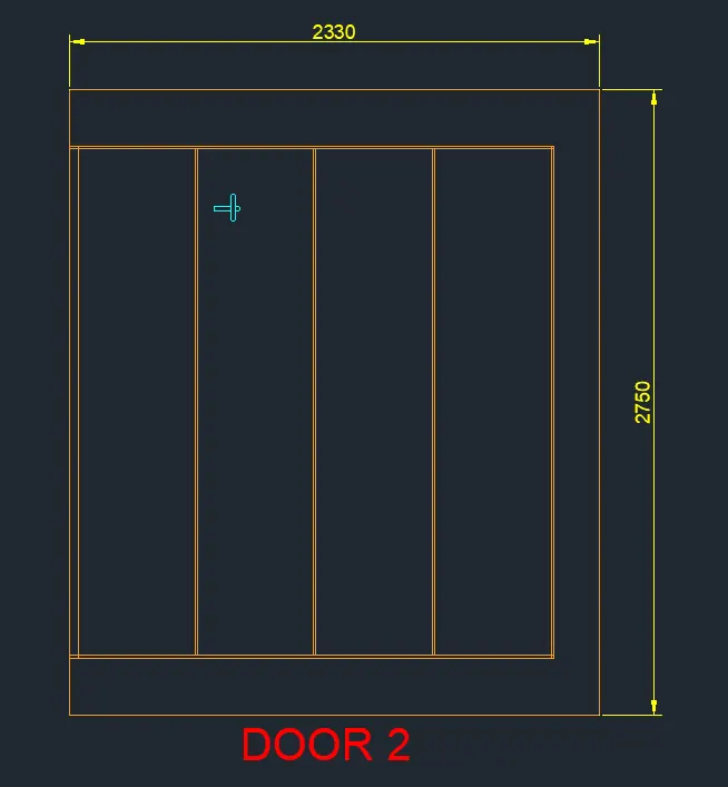
RESULT- The door types for warehouse are created and converted them as a block using AutoCad tool.
Q.3 Create each symbol as a block with the name given in the legend. After creating the blocks arrange them in the legend as shown in the Figure.
PROCEDURE-
A new layer is created in the name of electrical legends and a suitable colour is assigned to it and made it as a current layer
Now all the electrical legends was drafted using line, rectangle,circle,and hatch command.
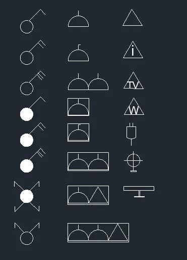
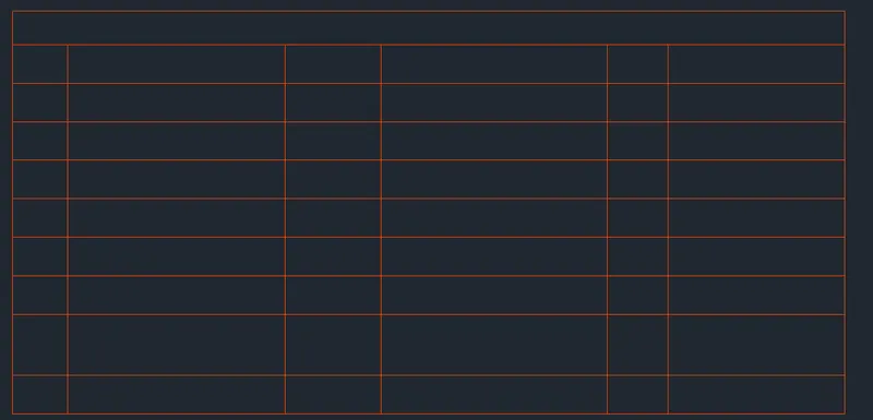
The table layer is created with suitable colour is assigned to it and made it as current.
using the line and rectangle command a table appropriate for filling details is created .
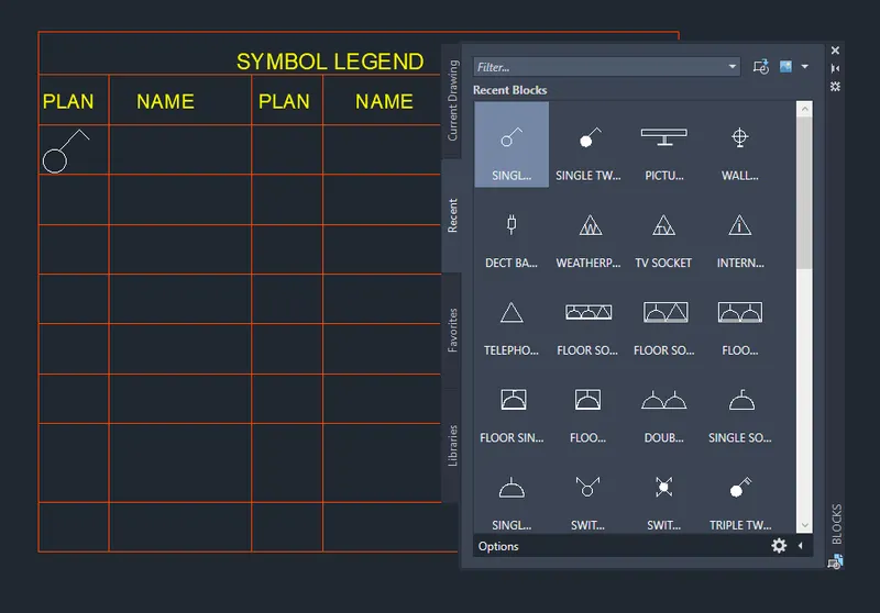
By using insert command all the blocks created are inserted to the table created.
A new layer in the name Texts is create d and suitable colour is assigned to it and made it as a default layer.
Now using the Multiline text all the headings and texts are entered.
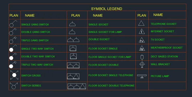
RESULT- The Electrical legends are created and converted them as a block and arrange them in a table.
Q.4 Create the door type for residential building as a block. Save the name of the blocks as type. Use given dimensions or assume dimensions as per industry standards.
procedure-
Type UN and press enter , set the units to engineering units.
Now the lower limit is set to 0,0 and the upper limit is set to 75',75' and Z enter A enter.
In the layer properties manager , a new layer is created in the name of door frames and suiyable colour is assigned to it and made it as current layer.
The door frames were created easily by using the line, start end direction arc, rectangle , offset , trim erase and filler command.
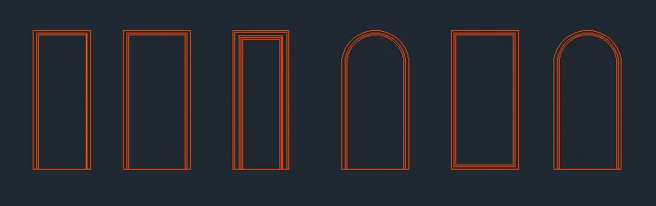
In door 1 and 3 the door handles were made first easily by the line command itself
In door 3 a small rectangular opening is made with rectangle and offset command.
In door 2,4,5 and 6 designs were made using rectangle and offset command and also a small circle was drawn at the bottom portion.
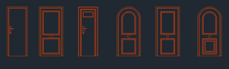
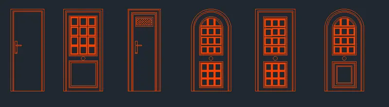
Door 3 was hatched using the particular hatch pattern and the door 3 drafting is now completed.
In door 2,4,5 and 6 a smal;l rectangle was made as shown and was then offsetted to the inside to create the design given.
Now a new layer is created in the name of dimension and suitable colour is assigned to it and made it as current .Now by using Dmilin command the dimension are given to the door as required.
And by using text command the door numbers are given.
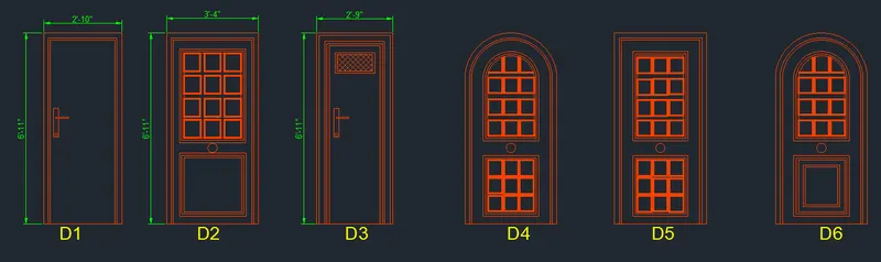
RESULT- The residential door frames are created and converted them as a block.
Q.5 Create each shape as a block as shown in the Figure. Save the block and insert them on the table as shown in the Figure.
PROCEDURE-
Inthe layer properties manager , a new layer is cretaed in the name of beams with suitable colour assigned to it and made is as current layer.
The beams are drafted as per the requirement using line, offset , fillet and trim command as shown below.
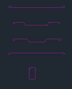
Now a text layer is created in the layer manager and a suitable colour is assigned to it and made it as a current laye.
All the texts are given as per the drawing using multiline text.
A new layer is created in the name of dimension with suitable colour assigned to it and mad it as a current layer.
Now by using Dimlin command all the dimensions are given as per the drawing.
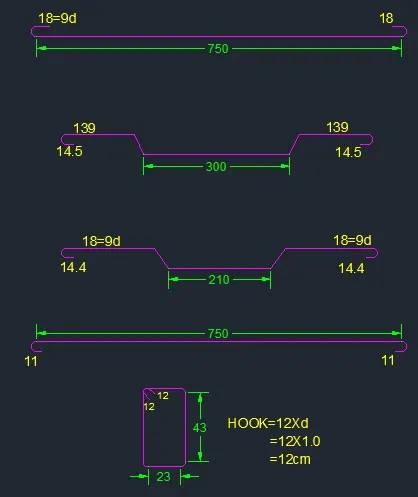
The table layer is created in the layer manger with suitable colour assigned to it and made it as current layer.
Now by using line , rectangle and offset command a table is created , and by using text command the table headings are given and the naming also done as per the drawing.
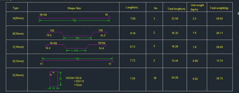
RESULT- The each bar bending drawing is created as a block and insert them in a table.