Project 1 _Creating an Architectural plan for the provided plot size and develop relevant basic structural drawings
AIM:
Design and Draft a layout of a residential building.
REQUIRED TOOLS:
LINE
XLINE
FILLET
OFFSET
TRIM
RECTANGLE
CIRCLE
BLOCK
INSERT
WRITEBLOAK
EDIT BLOCK DEFINITION
MTEXT
MULTILEADER
LAYER PROPERTIES
ANNOTATIONS
DIMENSIONS
EXPLODE
HATCH
ARRAY
SET OUT THE DRAWING:
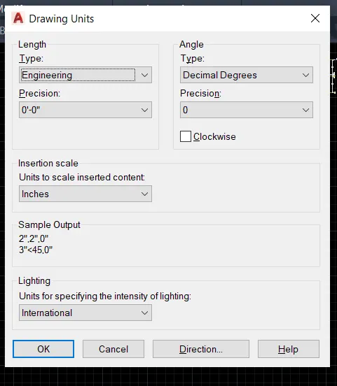
UNITS:
COMMAND: UN >
TYPE: Engineering
Precision: 0'-0"
Insertion scale: Inches
LIMITS
COMMAND: LIMMAX >
Set the maximum limits of the drawing sheet for better sketching. then
Zoom > All >
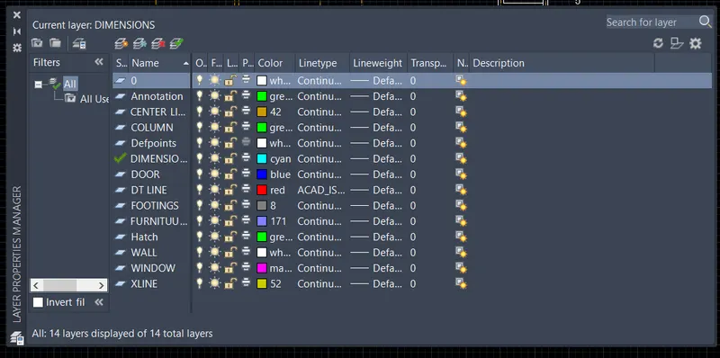
CREATING THE LAYERS:
Invoking the tool:
RIBBON: Annotate > Layer Properties>
ARCHITECTURAL DRAWING:
SKETCHING THE RESIDENTIAL BUILDING PLAN:
PROCEDURE:
RECTANGLE:
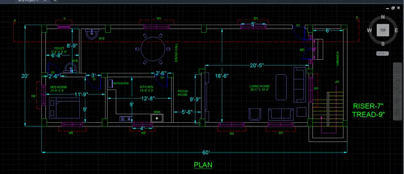
Creating one rectangle box with a given plot size as 60' x 20' by using the Rectangle tool
Invoking the tool
Command: REC>
Exploding the Rectangle by using EXPLODE TOOL
Invoking the tool
Command: EXPL>
select the object for exploding
OFFSET:
Creating the wall thickness of the building at all four side
Invoking tool:
COMMAND: OFF>
For External wall thickness taken as 9", so the value of the offset is given 9" and offset all four sides of the wall
Creating VARANDA by using an offset of 6' from the entrance and 9" wall thickness then
created LIVING ROOM with a dimension of 20'-5" x 18'-6" and given thickness of wall 9" after that
creating POOJA ROOM with 5'-6" x 9'-9" dimensions, given the 4.5" thickness of the wall and
creating the KITCHEN ROOM 12'-8" X 9' and wall thickness will be 4.5" after that
Creating the BEDROOM with dimensions of 11'-9" x 9' and creating the TOILET with dimensions of 6'-8" x 8'-9".
TRIM:
Trim all extended lines over the plan and door openings.
Invoking the Tool:
COMMAND: TR>>
CREATING THE COLUMN ON THE PLAN:
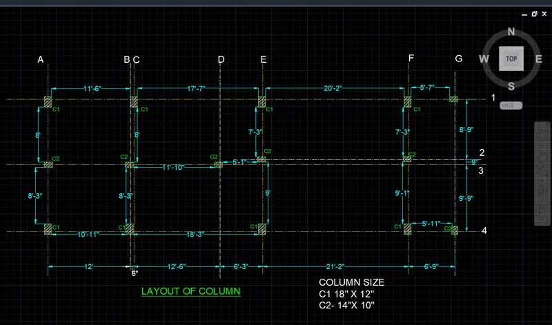
The size of the column (C1) = 18" X 12" and (C2) = 14" X 10"
Creating one rectangle with a size of 18" x 12" and Copied that rectangular column and past at required places similarly 14" X 10" Column created and placed at their respective places.
C1 columns are placed on External sides and
C2 columns are placed in insides to overcome the Bending moments of the beam.
CREATING THE DOOR:
LINE:
Drawn the Horizontal line with 3' length and 4' vertical length,
1" offset the vertical line for door panel thickness, and the other side created one frame, then create a circle by taking two endpoints, trim the extended lines. similarly, MainDoor and D1 were also drawn.
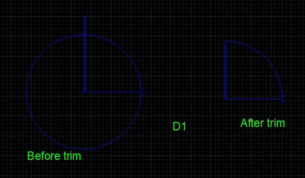
MD - 4'
D - 3'
D1 - 2'-6"
BLOCK:
Converting the Door drawing into the BLOCK for reducing the time for creating more drawings.
Invoking the tool:
COMMAND: B>
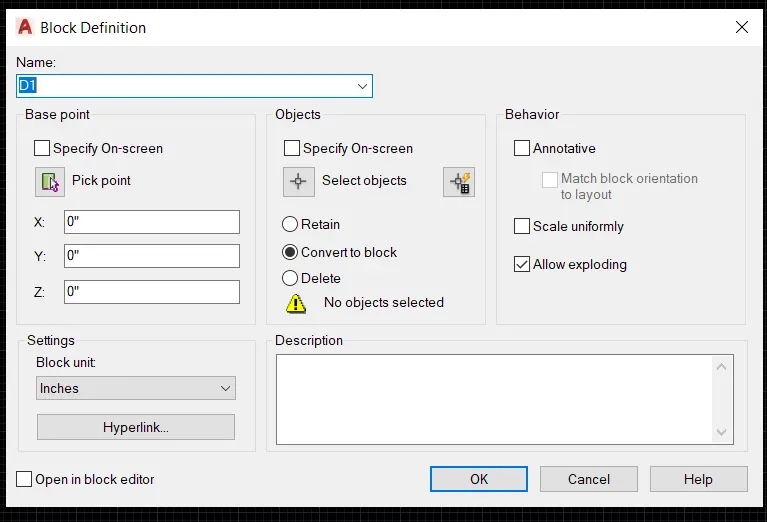
Select the object by window crossing method and pick the pointed corner of the door for placing the center of the wall, and click OK>
Similarly to Other doors also,
INSERT:
For inserting the door at their opening by using INSERT tool.
Invoking the tool:
COMMAND: I>
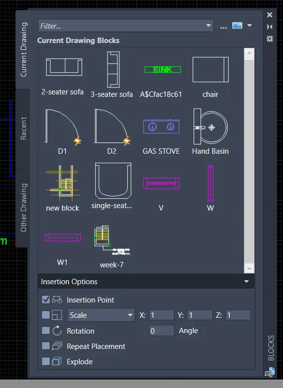
EDIT BLOCK DEFINITION:
Editing the Block for FLIPING the door for better to place.
Invoking the tool:
Command: BEDIT> OR
Double click on the Block >
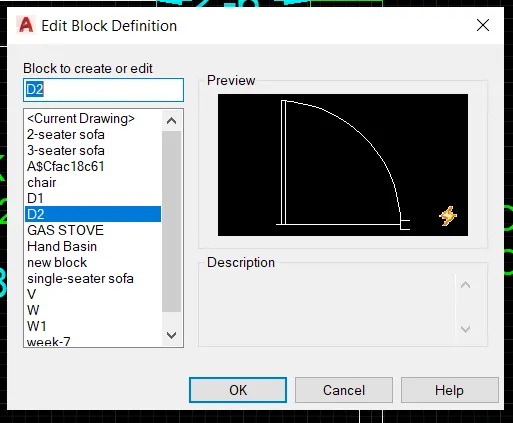
Select the Block which one is going to edit> press OK>
PARAMETERS > FLIP>
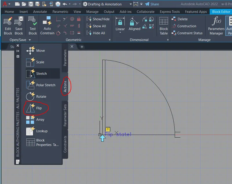
Creating the Up & Down FLIP.
Select the base point of the door and select the endpoint of the door then place the Flip label location Corner of the door, as shown in the below figures.
ACTION> FLIP > Select that label >
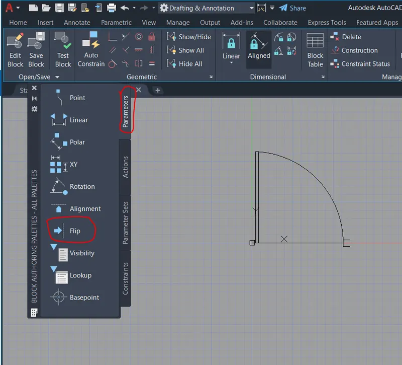
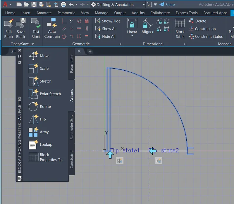
Creating the Left & Right FLIP.
Select the base point at the center of the door and select the vertical point of the door then place the Flip label location center of the door, as shown in the below figures.
ACTION> FLIP > Select that label >
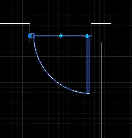
TESTING THE BLOCK:
Invoking the tool:
RIBBON: Open/Save > Test Block >
Then Close Test Block >
Then Close Block Editor >
CREATING THE ITEMS OF FURNITURE:
3-Seater Sofa and 2- Seater Sofa single sitting sofa, Gas stove, Washbasin, Dining Table, Chairs, Refrigerator, Water closet, Sink, Bed, tables, etc.,
SOFA, TABLE & BED:
created by using Rectangle, Explode, Offset, Trim & Fillet tools
Creating one rectangle by assuming the lengths and exploded that rectangle, offset the line, and trim the extended lines
DINING TABLE AND CHAIR:
Created one Circle by assuming the diameter and sketches out one chair, spread that chair around the table by using the ARRAY tool
Invoking the tool:
AR>
select the chair and choose the POLAR ARRAY type, Click the origin point of the circle. >
Converting all the pieces of Furniture into the BLOCKS and placed at required places.
CREATING THE WINDOWS AND VENTILATOR:
Creating a rectangle with dimensions of (W1) 5' x 9" and (W2) 4' x 9", drawn one center line in the rectangle, and dimensions of Ventilator 2'-6" x 9"
Converting into BLOCKS and INSERT at required places.
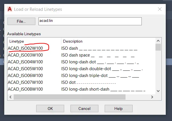
SUNSHADE PROJECTION LINES:
Creating one New Layer and Line type is loaded ACAD_ISO02W100
LINE:
Creating the projection line at windows.
SKETCHING THE STEPS:
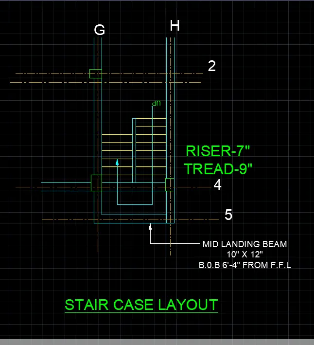
Staircases are created at the Left side of the entrance, Dimensions taken as RISER-7" and TREAD-9". LANDING WIDTH-2', drawn the one-step and offset to that step, second flight step are shown as hidden, it will go upward, the Direction shown by using Multileader tool.
ANNOTATIONS:
By using the MTEXT tool gives the name of the room, furniture, some other annotations
Invoking the tool:
COMMAND: MT>
DIMENSIONS:
Plotting the dimensions of all rooms and building layout by using DIMLINEAR.
Invoking the tool:
COMMAND: DIMLIN>
RESULT:
SKETCHING THE ELEVATION:
PROCEDURE
X LINES:
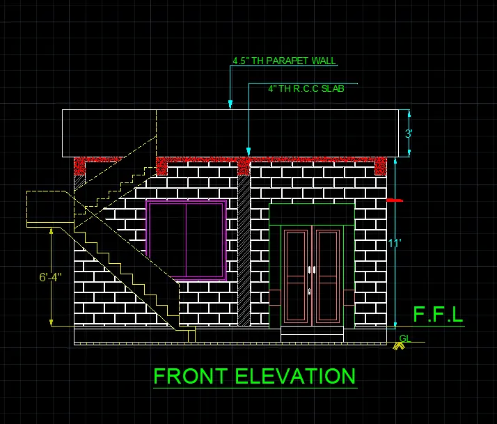
Create the Horizontal XLINES over the plan by indicating the columns, beams, windows, sunshade, main door, and Staircase
Draw the one vertical line on the XLLINES.
OFFSET:
Offset the vertical line for creating the top level of the slab 11' from FFL, 3' Parapet wall over the slab.
TRIM:
Trim all Extended lines over the plan and Elevation.
CREATING THE SUBSTRUCTURE:
2" thick Blast Furnace Slag below the P.C.C and the thickness of P.C.C will be 10" then 2" Flooring over the P.C.C
Trim that Extended line over the p.c.c and flooring lines.
CREATING THE DOOR AND WINDOW:
Create the window sill level from the F.F.L level 3' and the Height of the window will be 5' and the width is 5'
Creating the Step in front of the Door:
Dimensions of the stair: 4' x 1' x 6"
TRIM:
Trim the all extended line.
Offset the Door height 7' from the FFL then creating the vision panels door frame, and pattern doors, patterns are created by using the rectangular tool, and door hinges and locker on the door.
CREATING THE STAIRCASE:
Calculating the No. of steps by using the Formula = Height of the building = 11'/7" = 132"/7" = 18 Risers.
Riser
Creating the stair starting with the riser of 7" then tread 9" doing same up to the landing of the stair then landing distance 3' and thickness of landing slab 4" Again creat the hidden stairs on next flight.
Creating the railing for supporting the users for preventing accidents on the staircases.
HATCHING:
Invoking the tool
COMMAND: H>
Select the patterns for the column ANSI32, and Slab concrete pattern will be AR-CONC, Brick wall pattern AR-B816C
Scale the pattern for better visibility.
DIMENSIONS:
Plot the Dimensions of the building and doors, windows, etc., By using the DIMLINEAR tool.
COMMAND: DIMLIN>
ANNOTATION:
Creating the multileader for showing the slab thickness, Parapet wall thickness.
COMMAND: MLEADER>
COMMAND: MTEXT>
RESULT:
SKETCHING THE SECTION:- AA:
PROCEDURE:
X LINES:
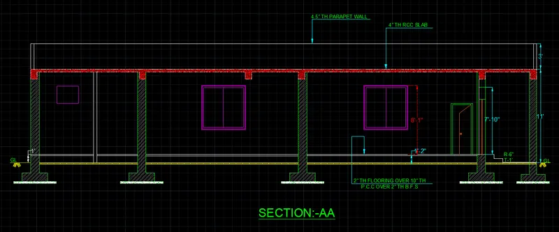
Creating the Vertical Xlines over the plan for the projection column, beams, walls, windows, doors of SECTION-AA
Created one horizontal line at the bottom
OFFSET:
Invoking the tool:
COMMAND: OFF>
Offset the horizontal line 11' up to slab level and 3' of parapet wall from the slab.
TRIM:
Trim all extended lines, over the plan,
Create the foundation below the ground level.
2" thick Blast Furnace Slag below the P.C.C and the thickness of P.C.C will be 10" then 2" Flooring over the P.C.C
Trim that Extended line over the p.c.c and flooring lines.
Create the window sill level from the F.F.L level 3' and the Height of the window will be 5' and the width is 5' and ventilator in Toilet 6' from FFL creat rectangle 2'-6" x 2'.
TRIM:
Trim the all extended line.
OFFSET:
Offset the 2" for creating the border of the window.
CREATING THE SLAB & BEAMS:
Offset the slab top line for the thickness of the slab 4" and Depth of the beam is 10",
TRIM:
Trim the extended line for creating slab thickness and beam depth.
SKETCHING OUT THE DOORS:
Offset the 6' line from the FFL for creating the head portion of the door
TRIM:
Trim the extended line over the door.
OFFSET:
Offset 1" for the frame and convert all lines into a single entity by using the JOIN tool.
HATCH:
Invoking the tool
COMMAND: H>
Select the patterns for the column ANSI32, and Slab concrete pattern will be AR-CONC.
Scale the pattern for better visibility.
DIMENSIONS:
Plot the Dimensions of the building and doors, windows, etc.,
ANNOTATION:
Creating the multileader for Giving the varies notation.
RESULT:
 :
:
STRUCTURAL DRAWING:
COLUMN LAYOUT:
PROCEDURE:
Copy the same plan and erase all furniture and staircase,
CENTERLINE:
Draw the centerline of the walls by using the centerline tool.
Invoking the tool:
COMMAND: CENTERLINE>
RIBBON: ANNOTATE > CENTERLINE>
ERASE:
Invoking the tool:
COMMAND: E>
Erase the beams and walls
ANNOTATIONS:
Creating the Grids for better understanding
Command: MTEXT>
DIMENSIONS:
COMMAND: DIMLIN>
Plotting the length of the column to column and grid to grid distances.
HATCH:
COMMAND: H>
Hatching the columns by hatch tool and choose the pattern type ANSI32 for indicating the steel structure.
Selecting the internal points for hatching and Setout the hatching scale for better visibility.
RESULT:
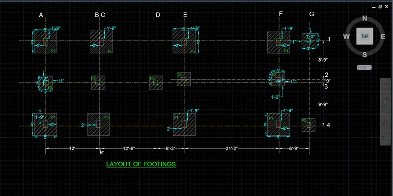
FOOTING LAYOUT:
PROCEDURE:
Copy the column layout and Creating the footing with dimensions of 5' x 5' and another footing size will be 3' x 3' Columns are placed center to the footing for having to strengthen the structure.
HATCH:
COMMAND: H>
Hatching the FOOTING by hatch tool and choose the pattern type ANSI32, and for the column Taken the hatch type AR_CONC.
Selecting the internal points for hatching and Setout the hatching scale for better visibility.
DIMENSIONS:
COMMAND: DIMLIN>
Plotting the Sizes of the footing and Grid to grid dimensions.
RESULT:
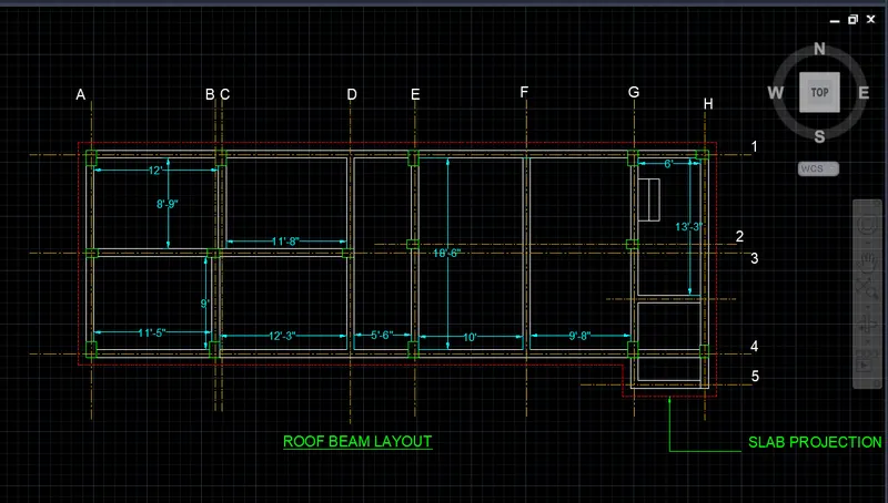
ROOF BEAM LAYOUT:
PROCEDURE:
Copy the same plan and erase all furniture and staircase,
SKETCHING THE BEAMS:
Roof beams are provided within 10 feet of length for
CENTERLINE:
Draw the centerline of the walls by using the centerline tool.
Invoking the tool:
COMMAND: CENTERLINE>
RIBBON: ANNOTATE > CENTERLINE>
ANNOTATIONS:
Creating the Notation of Grid for better understanding
Command: MTEXT>
DIMENSIONS:
COMMAND: DIMLIN>
Plotting the length of the Slabs
Creating the 9" slab projection around the building.
RESULT:
STAIRCASE LAYOUT:
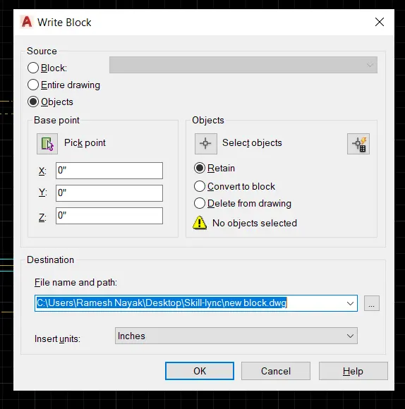
Creating the WRITE BLOCK:
Invoking the tool:
COMMAND: W>
Selecting the staircase portion and selected the pick point of the object
Selecting the File path to save the block >
INSERT:
Inserting the block by using the INSERT tool
Invoking the tool
COMMAND: I>