Project 1 _Creating an Architectural plan for the provided plot size and develop relevant basic structural drawings
AIM= Design and Draft a layout of a residential building
INTRODUCTION=
a. Plot Size: 60’x20’(18.3m x6m)
b. Orientation- Facing East
c. Develop the following: 1. Architectural Drawing (Floor Plan, Elevations, and Sections) 2. Structural Drawing (Column, Bean, Footing Plan)
COMMAND=
- Line
- Polyline
- Circle
- Arc
- Dimliner,Dimcontinue,Dimensiion
- trim
- text
- offset
- erase
- hatch
- layer
- copy
- scale
- fillate,,,,,,etc
PROCEDURE=
- Open the AUTOCAD software,start from the scratch
- set the units as decimal and select ok and Set the limits
- go to layer properties create a ne layer and the layer and choose the colour and close it
- Architectural drawing
1. plan
2.elevation
3.section
- Structural Drawing
1.Column
2.Beam
3.Footing Plan
- ARCHITECTURAL DRAWING:-
- PLAN:-
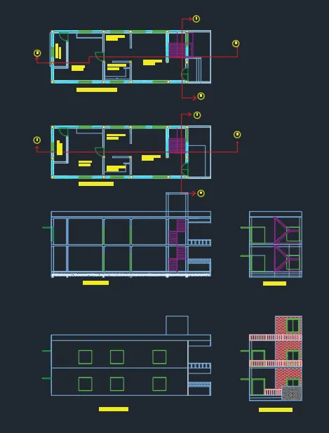
- Using the line command drawn the plot boundary of 18.3m x6m
- The building's main entrance is facing the east direction
- Using the commands line,offset,fillet and trim
- Starting the drawing main door as east face and diveded the area for stair case, car parking,and hall,kitchen bedroom and bathroom.
- using offset command created wall of building out wall as thickness off 250mm and inner wall as 150mm
- Changed the lines withhelp od layer command wherever required and i created my own plan for the project.
- it is planed as per VASTHU
- Main door :east
- kitchen:south- east
- pooja room :north- east
- Living Area : facing east
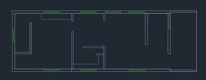
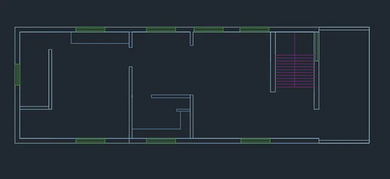
- after placing the windows going to create starcase,using the line.and offset command.
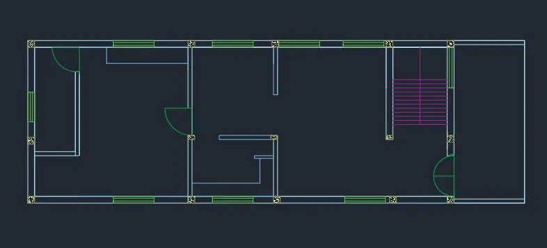
- Using line command i have created columns of size 250*250mm and 150*250mm and after using the hatch command hatched the coloumn of AR-CONC .and adjust the scale of hatching

- After placing the coloumn hatched the wall and gave the name with the help of text and drawn the first floor and completed plan and divided section A-A AND B-B
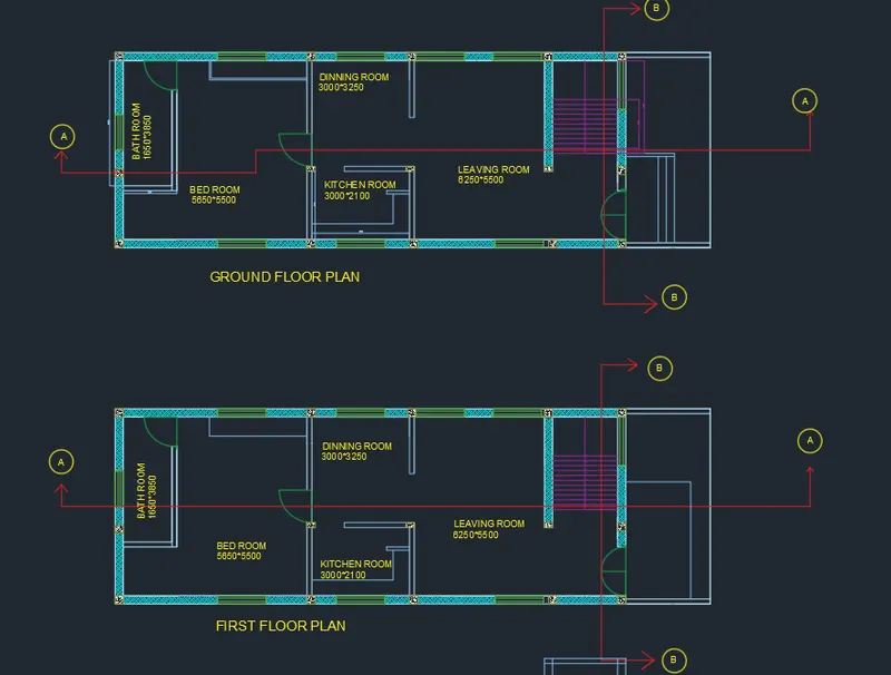
- After done with plan moved for section A-A AND SECTION B-B
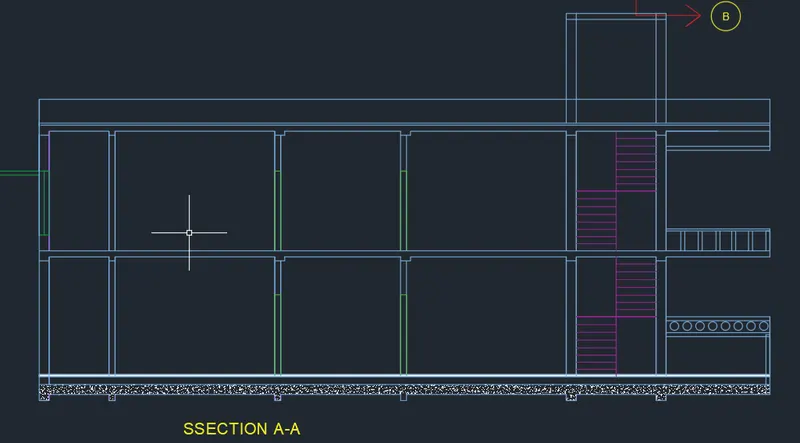
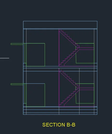
- After section drawn elevation of both side elevation and front elevation
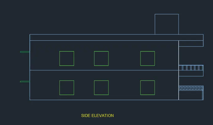
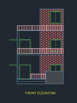
- and finally done with plan section and elevation.
2.STRUCTURAL DRAWING:
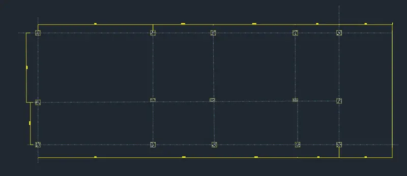
1. COLUMN LAYOUT-
- Created column as size 250*250 and 250*150 in different location as shown in the figer
- select and construction line as ISO DASH made center line in the horizontal and vertical direction as shown in the figer
- trim the unnecessary line using trim command and press the ESC botton once it finish
- select the dimension tool and select the line and measure it
- and after that used contionue dimension measure all the line
- give the text as per drawing requirment in the figer
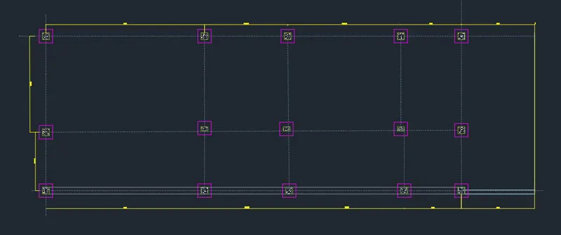
2.BEAM LAYOUT AND FOOTING LAYOUT-
- draw the beam as per thickness
- select and construction line made beam line in the horizontal and vertical direction as shown in the figer
- trim the unnecessary line using trim command and press the ESC botton once it finish
- select the dimension tool and select the line and measure it
- and after that used contionue dimension measure all the line
- give the text as per drawing requirment in the figer
- made the footing with help of line with differnt color
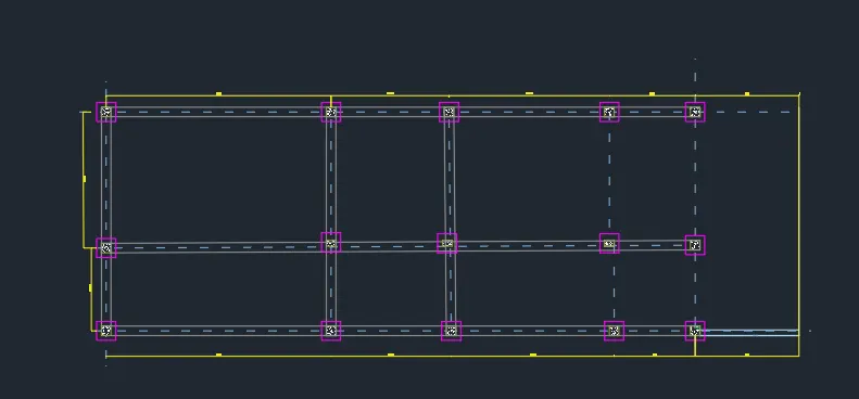
- RESULT= drawn 1. Architectural Drawing (Floor Plan, Elevations, and Sections) 2. Structural Drawing (Column, Bean, Footing Plan