Creation of Multiple viewports, Scaling the drawing and setting in Template in AutoCad
AIM: Create a layout of the Plan and Section A of the project in Challenges 7, using the template Tutorial-mArch.
INTRODUCTION: Create a layout of the Plan and Section A of the project in Challenges 7, using the template Tutorial-mArch.dwt in a scale as given in the Figure. Use the MV command to create the viewport of the size as shown in Figure. Also, use the ATTEDIT command to edit the information in the title block. Use A1 size for the layout. Take a plot.
PROCEDURE:
- First, select the drawings of the plan and elevation,
- going to template choose new and pic up the template M arch click ok,
- after that using ATTEDIT the title, sheet no, date, and name all are changed by using attedit automatically,
- after that created each view for both plan and elevation as going to view command, created the model views,
- next going to viewports choose the vertical 2view ports as per requirement,
- in the first viewport selected pasted the view of the plan and make that scale 1:50 by clicking the middle of it,
- same as 1st do the second and elevation pasted by using the view panel set the view in 1:50 scale by selecting the middle node,
- after that click on the page set up choose name type as plan, and elevation chooses the type of page as A1 chosen the window to apply the layout click on preview ok.
- save the file with the name as plan and elevation final layout.
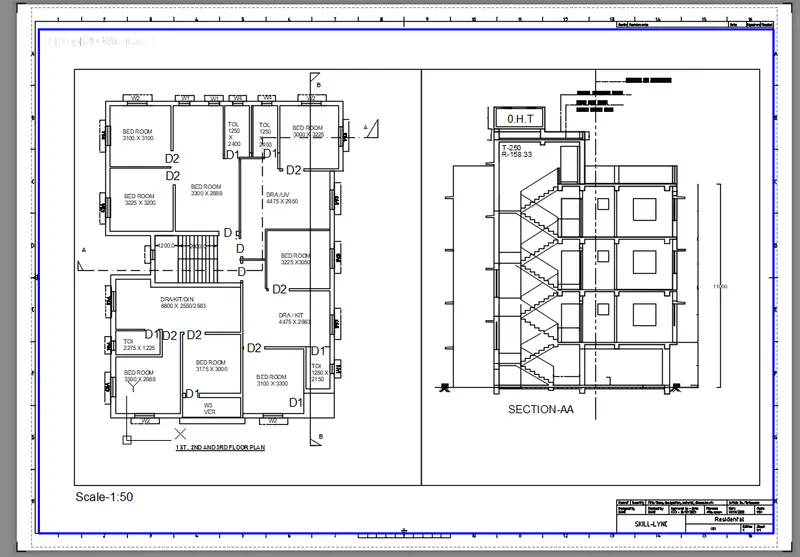
RESULT:
Created a layout of the Plan and Section A of the project in Challenges 7, using the template Tutorial-mArch.dwt in a scale as given in the Figure. Used the MV command and created the viewport of the size as shown in Figure. Also, used the ATTEDIT command to edit the information in the title block. Used A1 size for the layout. Taken a plot.
AIM: Create a layout of the Kitchen drawn in Challenge 9 as shown in Figure.
INTRODUCTION:
Create a layout of the Kitchen drawn in Challenge 9 as shown in Figure. Use the scale as shown in the Figure. Use an A4 Size page for the layout. Take a plot.
PROCEDURE:
- open the kitchen drawing file,
- created the views as per show in the challenge, like by clicking view to create a model view like for close up of the above counter plan as well as below counter plan.
- next, go to the template and rename it to the kitchen,
- next, go to viewport or Mview command choose the 4 viewports that are fitted by using the fit option,
- later that by using the MS command going to the first viewport pasted the first view of the above counter-plan by going to the view tab selecting the above counter-plan view,
- below that view board pasted entirely above the kitchen platform by using the view command,
- top 3 viewports by using view chose the below kitchen layout platform,
- last viewport entire kitchen plot form of above kitchen platform pasted,
- each one scaled by using the center node of each portion,
- Click on the plot go to a page set up choose the pdf and selected the page of A4 with 11inch x 8inch,
- Click on the plot to save the file ok.
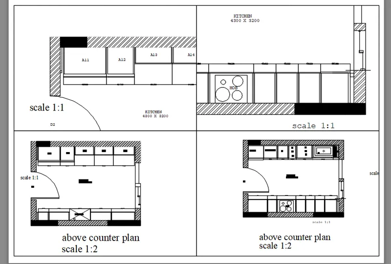
RESULT: Created a layout of the Kitchen drawn in Challenge 9 as shown in Figure. Used the scale as shown in the Figure. Used an A4 Size page for the layout. Taken a plot.
AIM: Create a layout of the section created in Challenge 9.
INTRODUCTION:
Create a layout of the section created in Challenge 9.
Use the scale as mentioned in the Figure. Use the MV command to create multiple viewports. Take a plot.
PROCEDURE:
- opened the file of industrial elevation file,
- going to viewports chose the 3 plots as we required,
- first, create the views in a model like going to view click on model view create the manhole view as duck view another one is a full view of the entire drawing,
- next go to the template rename it by clicking the right click as industrial elevation,
- after that by using the MS command-click on the first viewport and go to views chosen for the entire view click on set current and apply ok.
- by clicking viewport center the scale is adjusted to 1:100,
- after that going to the second viewport choose the manhole view from the view set current,
- set the scale of viewport drawing by clicking center node as 1: 30
- same as the 2nd viewport 3rd viewport also imported from the view tab and arranged the scale as 1:30,
- after that using the PS command paper set by using the pan command,
- by right-clicking on the template going to the page set up selecting the name or giving the new name as industrial final layout,
- choose the paper as A4 choose the window and applied the layout click on ok,
- save the file as an industrial layout.
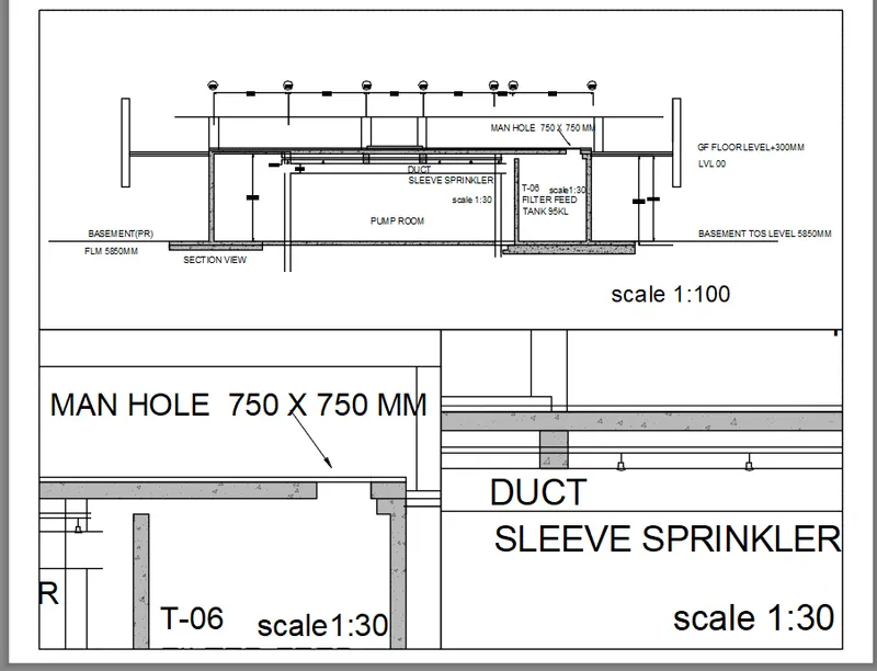
RESULT:
Created a layout of the section created in Challenge 9.
Used the scale as mentioned in the Figure. Used MV command and create multiple viewports. Taken a plot.