Project 1 _Creating an Architectural plan for the provided plot size and develop relevant basic structural drawings
Aim:
- To Design and Draft a layout of a Residential Building for a Plot Size 60' X 20' (18.3m x 6m).
- To Draft the Architechtural drawings such as Floor Plan, Elevations and Section of the Builiding.
- To draft the Structural Drawings such as Column, Beam and Footing Plan of the drafted Building.
Introduction:
- The Floor Plan of a building is nothing but the Bird eye view if the building is cut at the Window Sill Level.
- The Floor Plan gives us the idea of the location of Rooms, Thickness of Wall, Location of Doors and Window etc.,
- The Section of the Plan gives the information the height of Floor Level, Doors, Windows and the projections that cannot be read in the plan.
- The Elevation of the Plan gives the view if viewed from outside of the building. We can have an idea how the building looks on the outside with all the doors and windows.
- The strutural drawings which include Column, Beam and Footing Plan gives us the reinforcement details used in the building which is the key to strength of the building.
- The Structural drawing should be very precise because the Reinforcement provided in the site are done with the help of these drawing only.
- The various commands used for Drafting and Designing the above Plan are
- Line
- Circle
- PolyLine
- Copy
- Move
- Offset
- Mtext
- Table
- Scale
- Hatch
- Leader
- Stack
- Erase
- Rectangle
- Extend
- Fillet
- Trim
- Construction Line
- Layer Properties
- Qleader
- Multi Leader
- Match Properties
- Ortho
- Dim Linear
- Dim Continuous
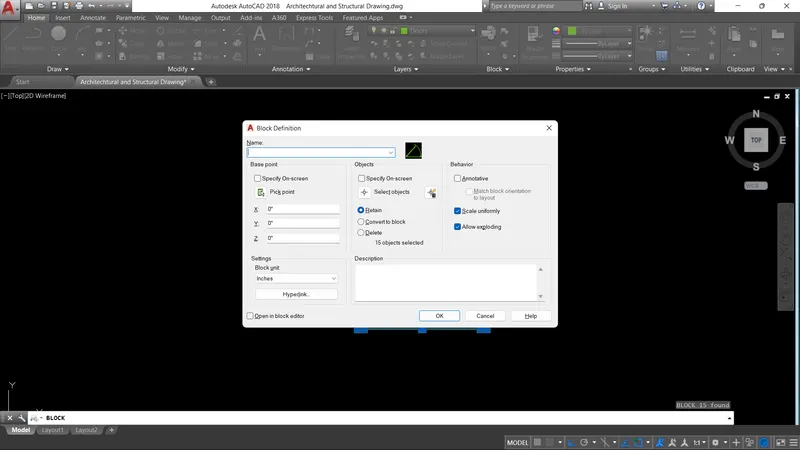
- Block
- Block Editor
- Insert
Procedure:
- The Floor Plan is drafted with the help of Vaastu and the orientation of the rooms are fixed.
- Decide the thickness of External and Internal Walls.
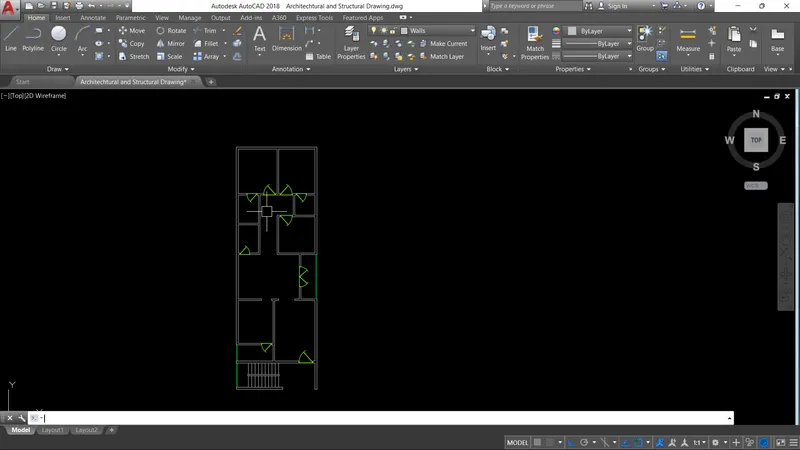
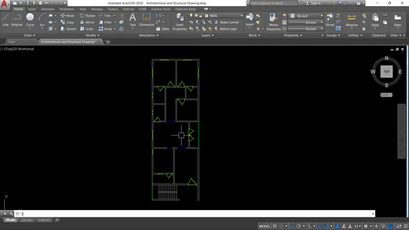
- Provide the Doors and Windows of standard width and thickness.
- Create certain blocks for each type of Door and Window.
- Draft the Plan with the help of available information provided by the Client.
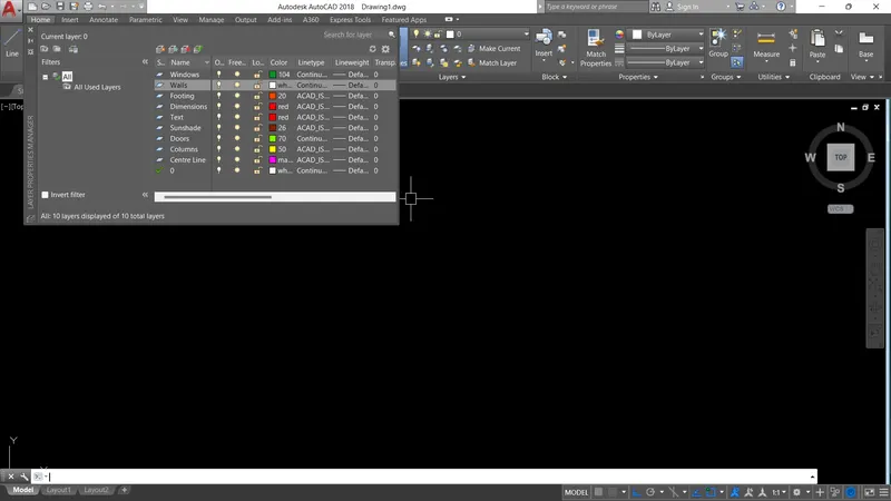
- Create various layers for walls, windows, doors, columns etc.,
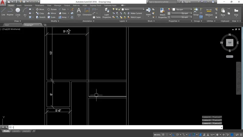
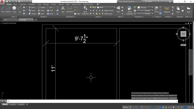
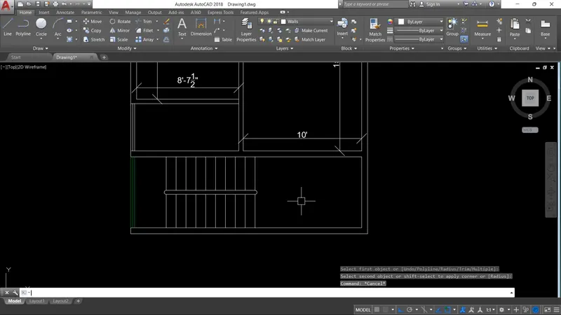
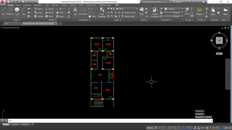
1. Plan:
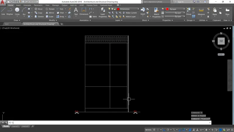
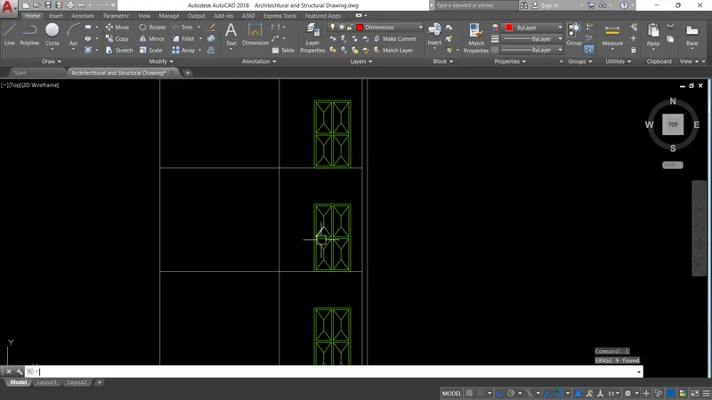
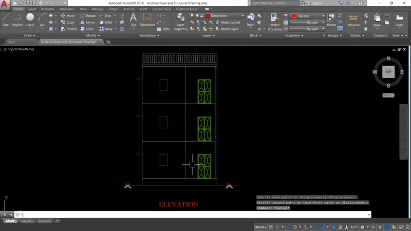
2. Elevation:
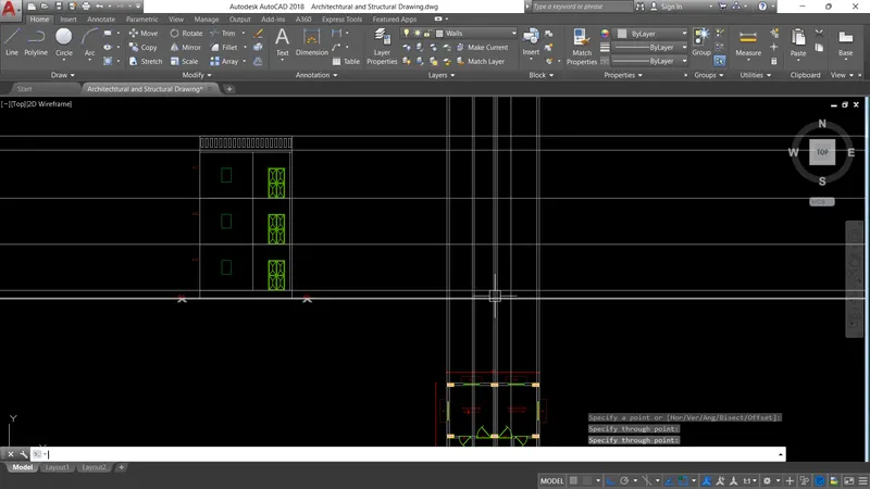
- With the help of Construction lines extend the points that need to be represented in the Elevations.
- For example the points of Door, Wall intersection, Windows etc.,
- Give the respective dimensions, Plinth Level, Ground Level etc.,
3. Section:
- Assume a section line across the plan through which we need to view the section of the plan.
- Give a seperate layer to the section line and name the section line.
- Draw the construction lines from elevation and plan to make the required intersections of door points, wall thickness etc.,
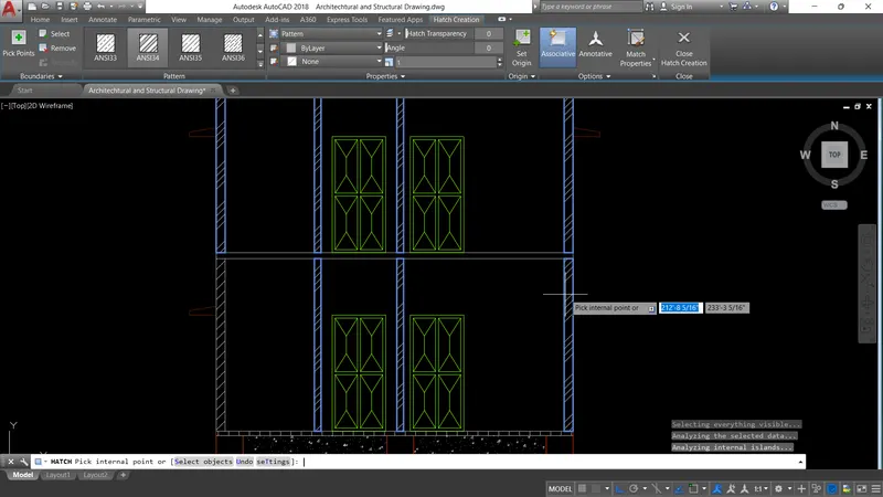
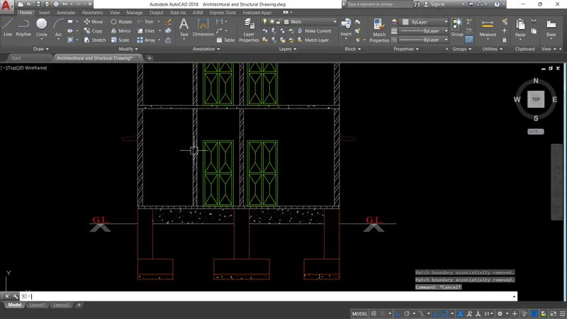
- Provide the required hatching and points such as Damp Proof Course thinkness, Slab Thickness etc.,
4. Columns:
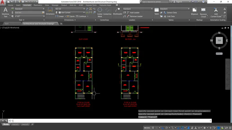
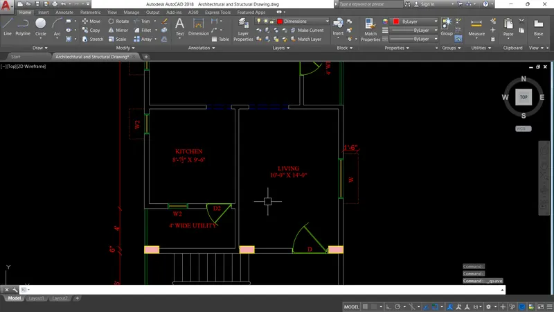
- Provide the columns at the required location with the dimensions.
- Convert the columns as a block so it will become handy while inserting the columns in the plan.
5. Column Position Drawing:
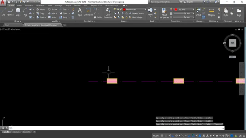
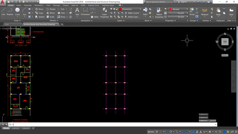
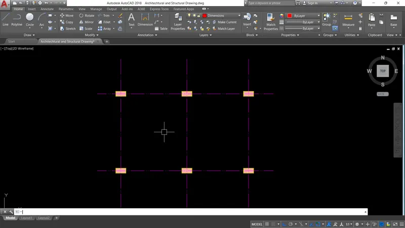
- As the columns are created as a different layer, Freeze all the layers and copy the columns aside for dimensioning.
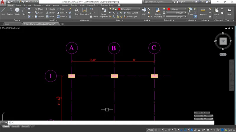
- After the columns are copied draw the centreline drawing in both x and y direction.
- This centreline drawing should be precise without any errors because the excavation and fixing of column position is done with the help of this drawing.
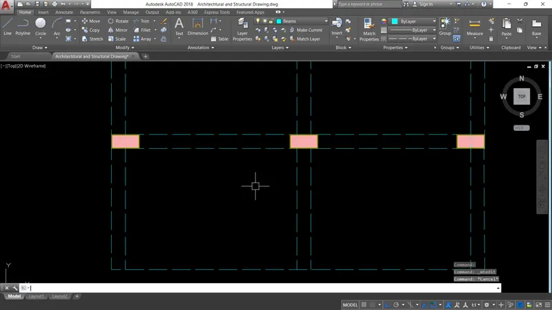
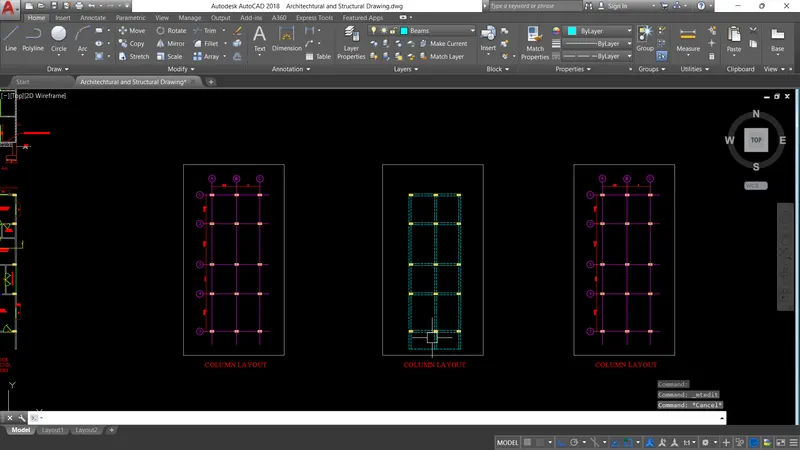
6. Beam Drawing:
- Draw the Beam outline with their respective width along the plan.
- Create a seperate layer for the beams.
7. Footing Drawing:
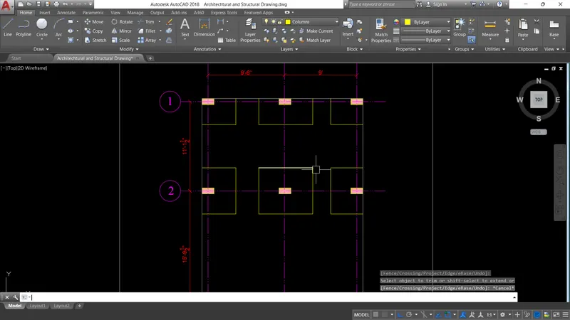
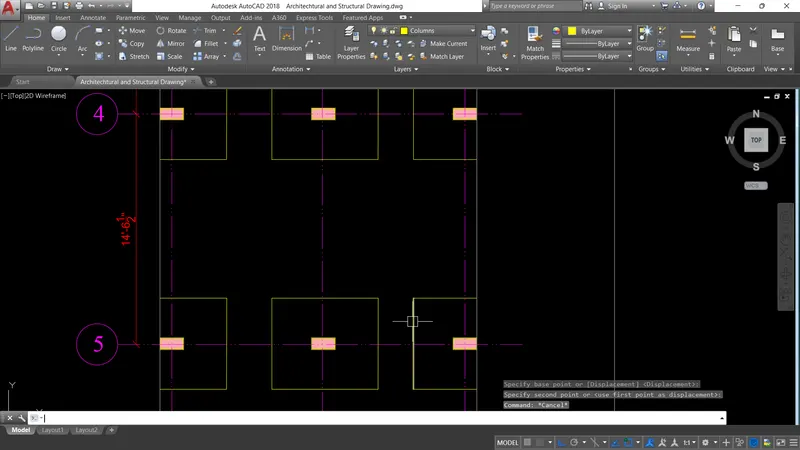
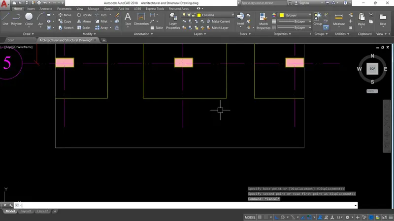
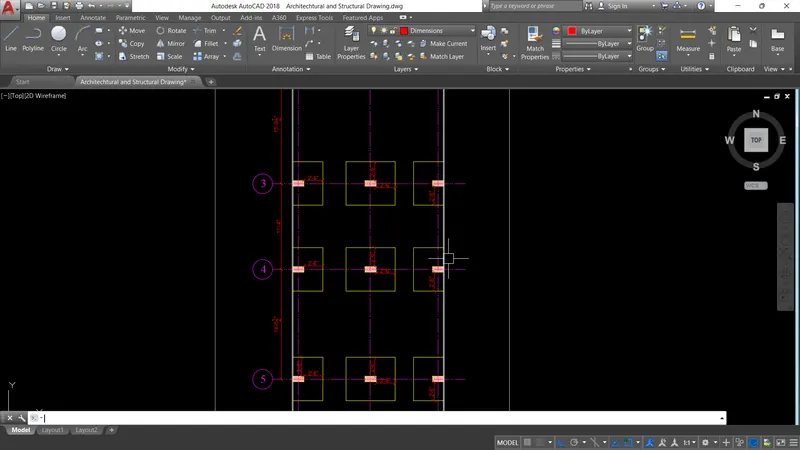
- The column position is copied and the dimensions of the footing are given in this drawing.
- A seperate layer is created for the drafting of Footings.
- The length and width of the footing are shown in this drawing.
- This entire is based on the centre line of the column position.
Result:
The Architechtural Drawing such as Floor Plan, Elevation, Section and the Structural Drawing such as Column Position, Beam Layout, Footing Position for a Plot size of 20' x 60' East Facing are drafted with the help of AutoCAD.
The drawing is attached.