Creating Bar Bending schedule, Different Door types, and Creation of standard drawing templates using AutoCad
Aim:
To Draft and create blocks of a Title Block, Legend for Electrical appliances, Door Frames of standard sizes and Bar Bending Schedule using AutoCAD.
Introduction:
- The block command is very useful when a certain plan or electrical drawing is being drafted.
- As all the notations are already saves as block we can insert them as required while drafting the plan of electrical layout or furniture layout etc.,
- Block editor is also used for editing a certain block for any corrections to the present block.
- The Field attribute is used for displaying the various charateristics of a block such as name, Block type etc.,
- The various commands used for Drafting and Designing the above are
- Line
- Circle
- PolyLine
- Copy
- Move
- Offset
- Mtext
- Table
- Scale
- Hatch
- Leader
- Stack
- Erase
- Rectangle
- Extend
- Fillet
- Trim
- Construction Line
- Layer Properties
- Qleader
- Multi Leader
- Match Properties
- Ortho
- Dim Linear
- Dim Continuous
- Block
- Block Editor
- Insert
- Define Attributes
- Attribute edit
- Field
- Block
- Block Editor
- Rename
Procedure:
1. Title Block:
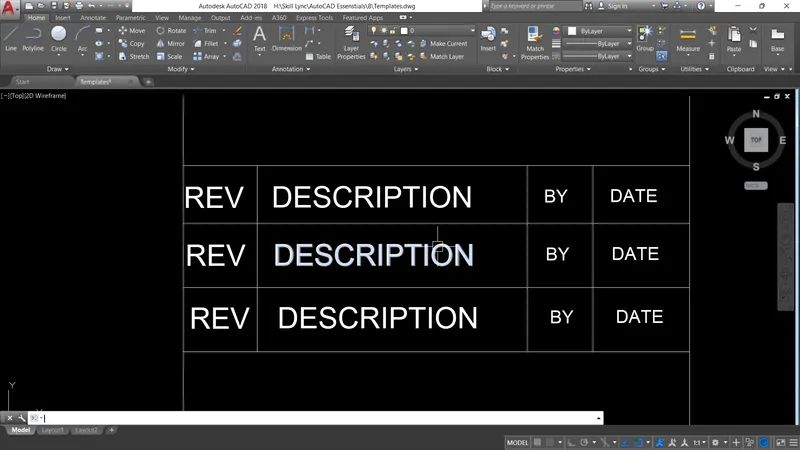
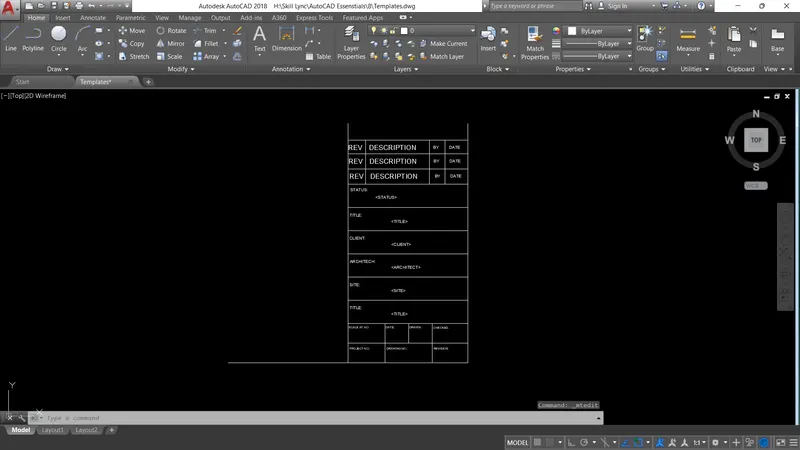
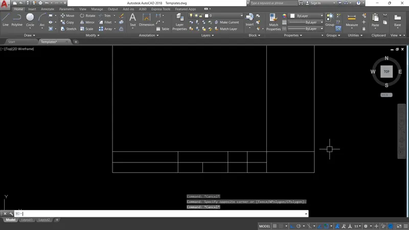
- Firstly draft the layout as shown in the question of required size.
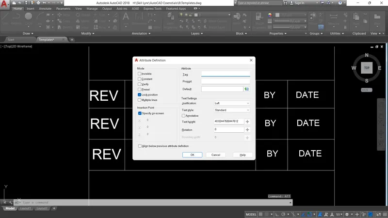
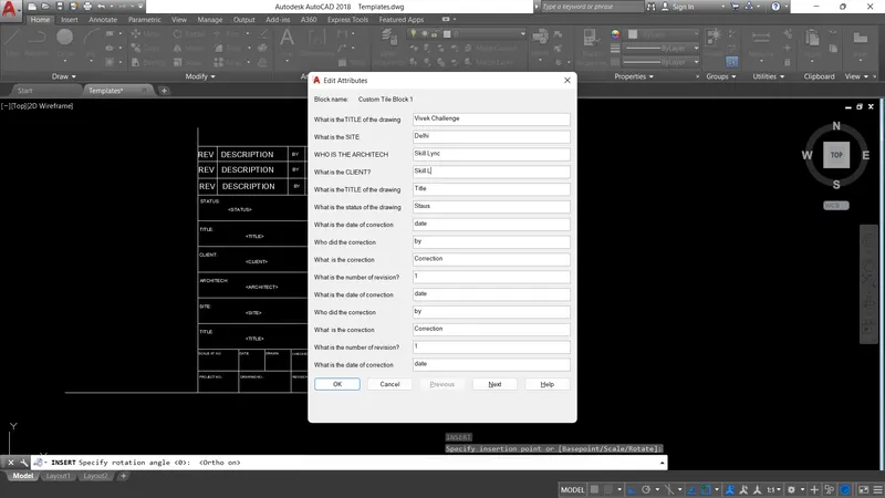
- Then using the Attributes command insert various attributes at the required locations.
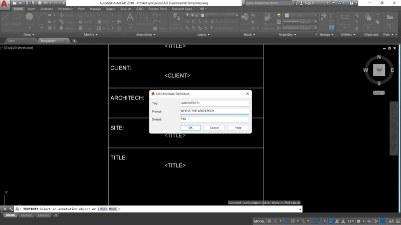
- Enter the Tag line, Prompt and Default display of the particular attribute.
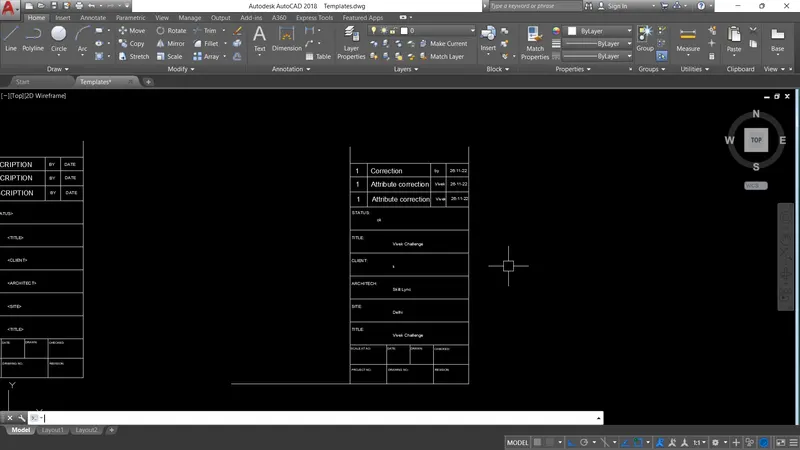
- Then convert the layout into block.
- While inserting the block, a pop up window will be opened and we can fill in the information which needed to be entered into the Attributes.
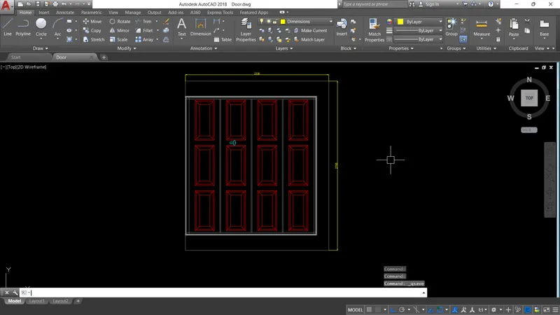
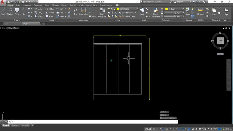
2. Door Frames:
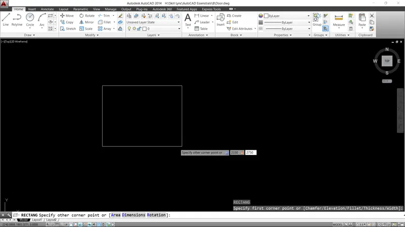
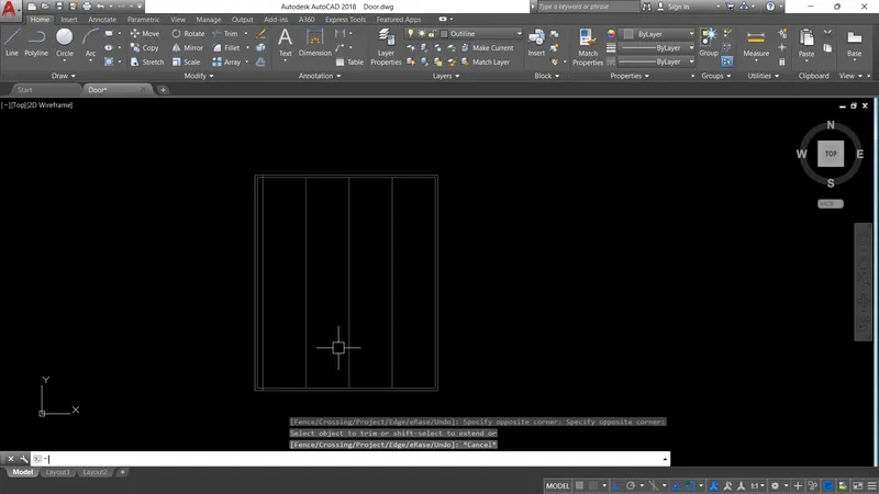
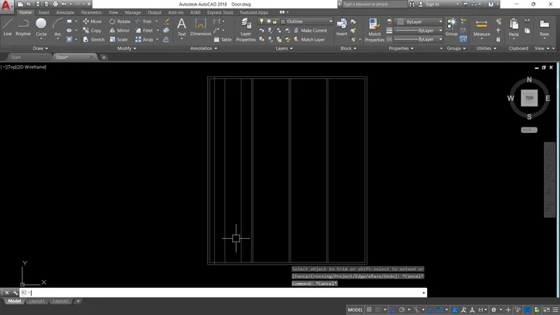
- Draw a rectangle for the outline of the door frame as per the given dimensions in the question.
- Now for taking the dimesions we can insert the picture of the door frame into the drawing.
- We can do this with the help of XREF command.
- Now scale the picture as per the dimensions and take the dimensions in the picture as reference for the drawing.
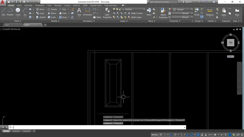
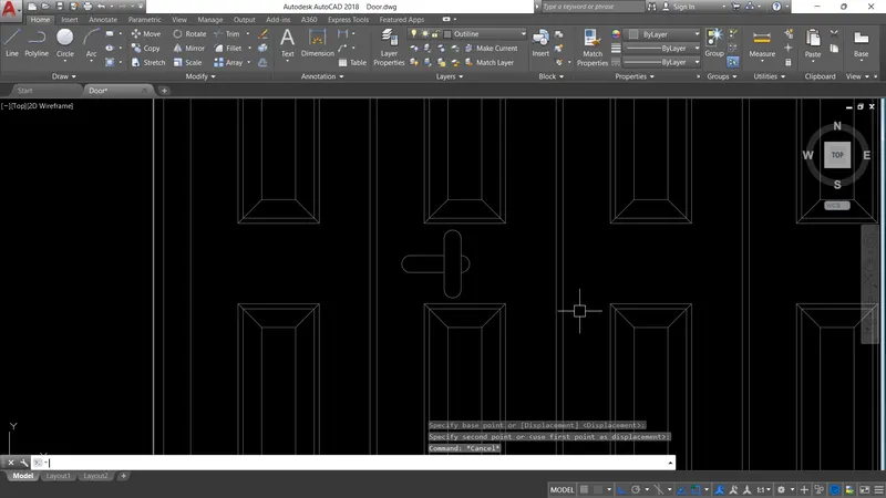
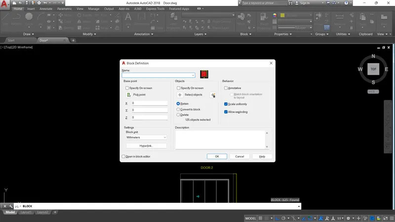
- After drafting the door convert it as a block with the help of Block command and give a name to the block.
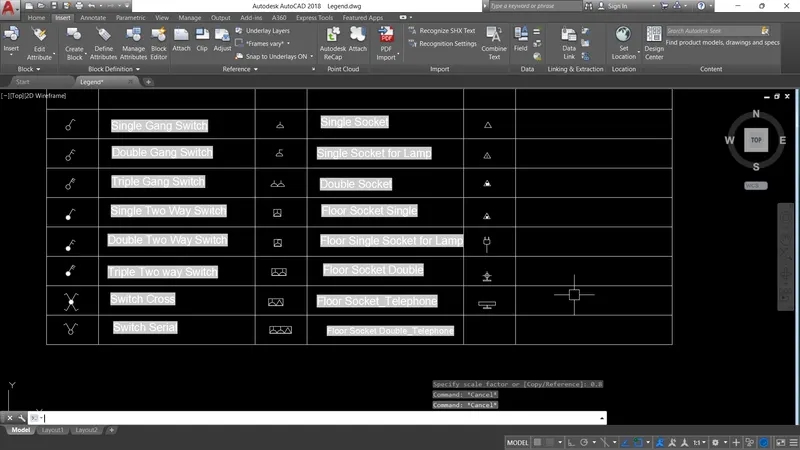
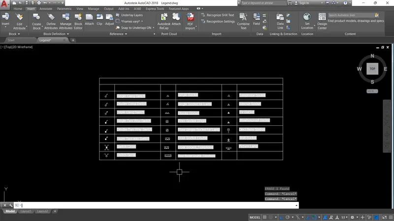
3. Electrical Layout Legend:
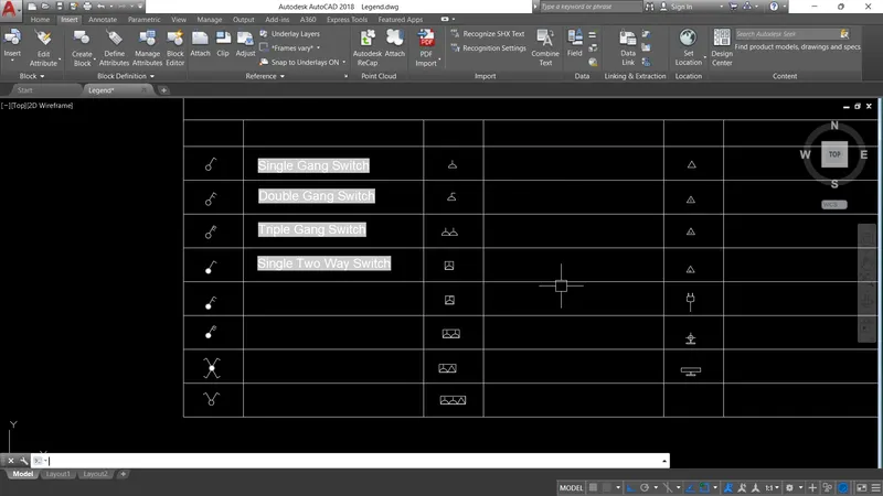
- Create seperate blocks for each every object which is to be displayed in the legend.
- Give the names to the respective blocks as how they should appear in the legend.
- Now insert every block in a tabular format.
- Now go to Insert>Field Option > Object > Select the Object > Name > Select the Font Style > Enter.
- Place the Field as per the requirement.
- If there are any changes to the block name, update the field and the name of the object will change.

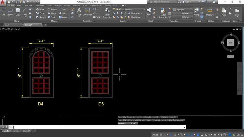
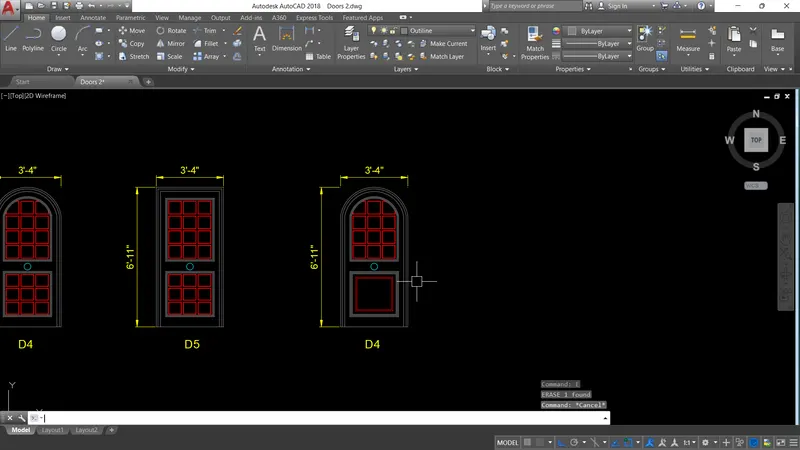
4. Doors:
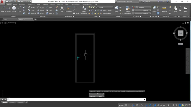
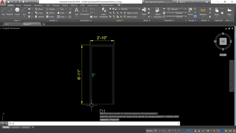
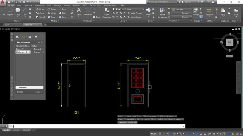
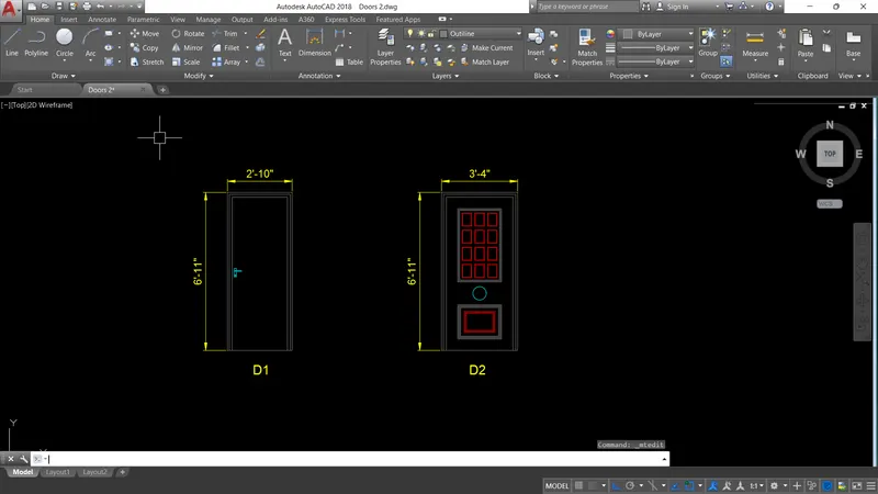
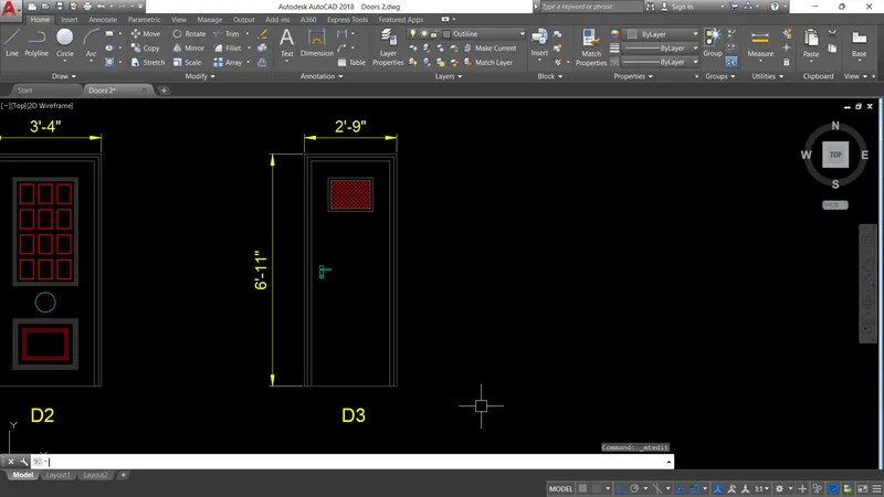
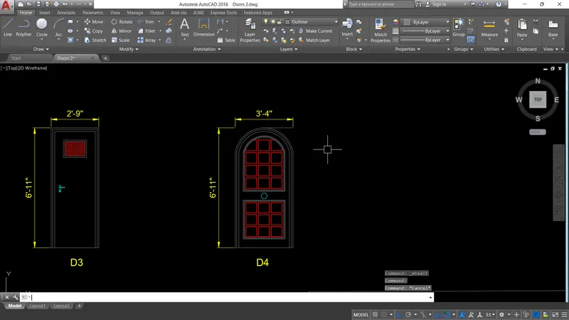
- Draw a rectangle for the outline of the door frame as per the given dimensions in the question.
- Now for taking the dimesions we can insert the picture of the door frame into the drawing.
- We can do this with the help of XREF command.
- Now scale the picture as per the dimensions and take the dimensions in the picture as reference for the drawing.
- After drafting the door convert it as a block with the help of Block command and give a name to the block.
5. Bar Bending Schedule:
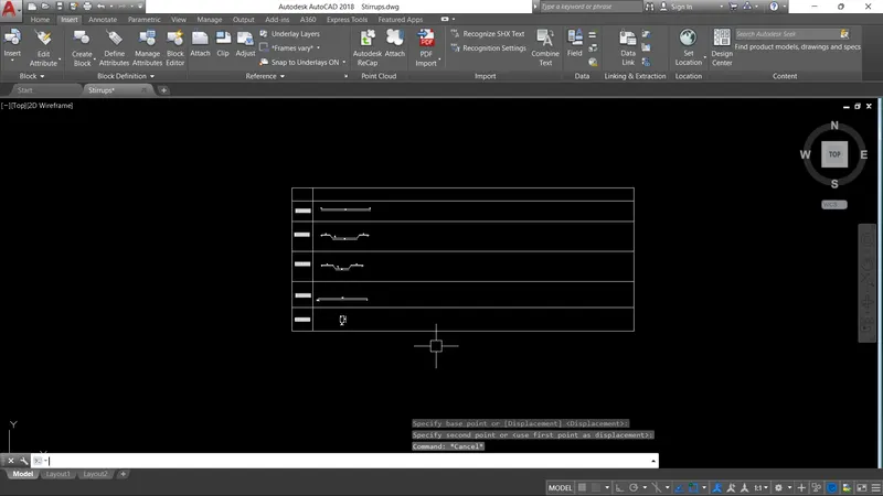
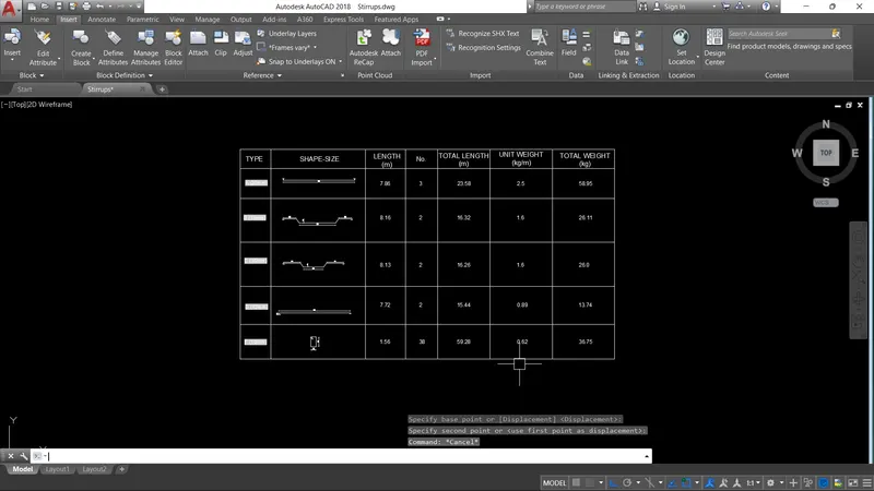
- Create the Shape and size of the bars as per given in the question.
- Create the block for each and every object and give an appropriate name.
- The with help of Attributes give the requried data to the block.
- We can use the help of Field command similar to that of its use in the drafting the legend of electrical layout.
- Arrange all the data similarly for aesthetic point of view.
Result:
The blocks are drafted and created for the Title Block, Electrical Layout Legend, Door Frames and Bar Bending Schedule. The Attributes and Field commands are used whenever usefu;.
The Drawing are attached.