Creation of Multiple viewports, Scaling the drawing and setting in Template in AutoCad
Aim:
To Create Multiple Viewports, Scale the Drawing and setting the Template using AutoCAD.
Introduction:
- Viewports are areas that display different views of your model.
- In large or complex drawings, displaying different views reduces the time needed to zoom or pan in a single view.
- Errors that you might miss in one view might be visible in another.
- The various tools used in drafting the Multiple View Ports and scaling the drawing are:
- View
- MView
- MView Setup
- Layout Setting Manager
- From Template
- Mtext
- Dimension
- Copy
- Model Space
- Paper Space
- Pan
Procedure:
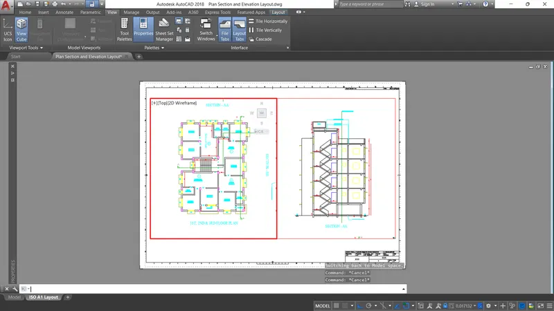
1. Plan and Elevation:
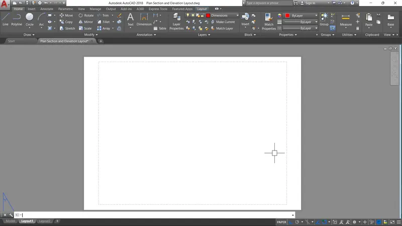
- Open the drawing and below the drawing space we can observe beside model there is another tab present with the name of Layout.
- Click on the Layout.
- Now delete the Viewport which is present and then right click on the layout.
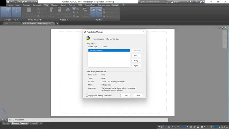
- Then Rename the layout and click on Layout Manager.
- Then fix the size of the paper.
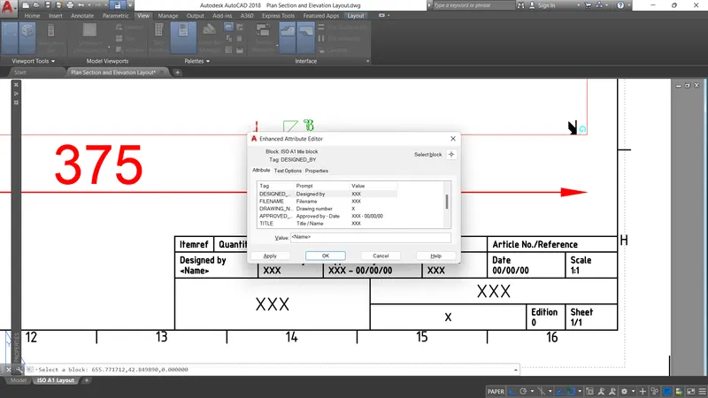
- Again right click on the layout and Click on From Template.
- Select the mArch Template and click on insert and edit the details using the Attribute Edit command.
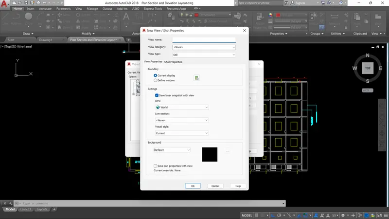
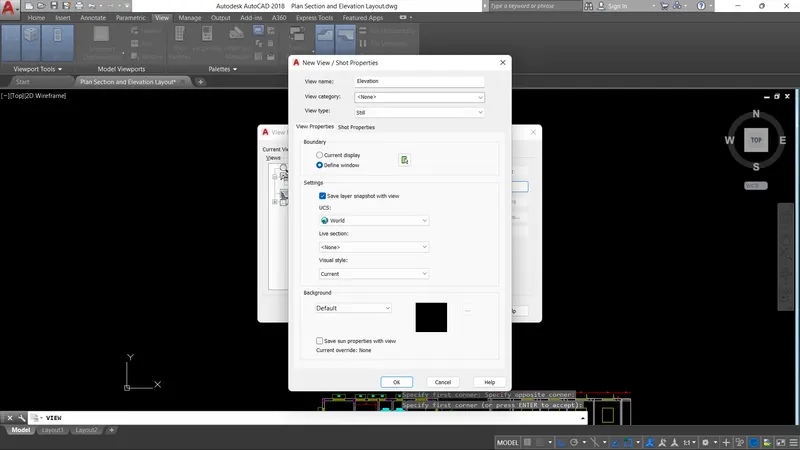
- Create view ports using the command view and insert them in the Layout.
- Select the required scale and with the help of Pan move them.
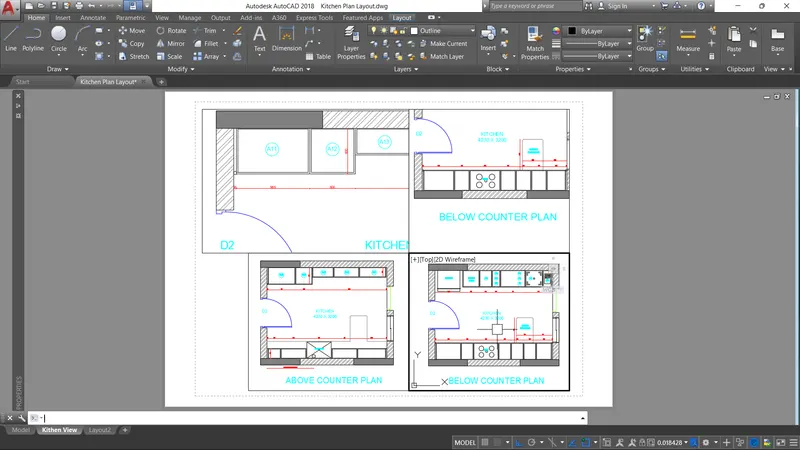
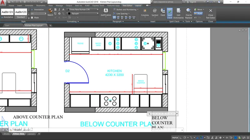
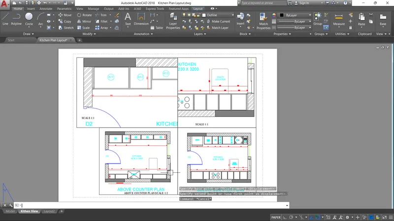
2. Kitchen Plan:
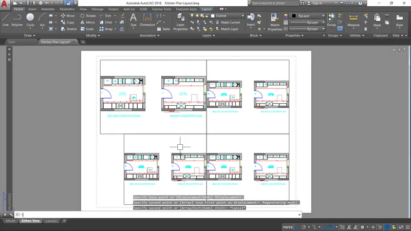
- Open the drawing and open Layout tab.
- Select the size of the paper and other properties.
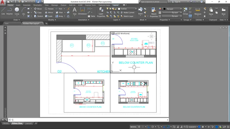
- Now create four view ports with the help of MV command.
- Use the Scale option in properties and adjust the size of the drawing as provided in the question.
3. Industrial Building:
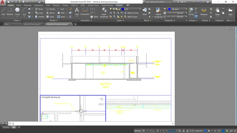
- Open the drawing and open Layout tab.
- Select the size of the paper and other properties.
- Now create three view ports with the help of MV command.
- Use the Scale option in properties and adjust the size of the drawing as provided in the question.
- Using the Mtext enter the text to be displayed.
Result:
We have done creating Multiple Viewports, Scaling the Drawing and Setting the Template in the Layout using AutoCAD.
The respective drawing are attached.