Project 1 _Creating an Architectural plan for the provided plot size and develop relevant basic structural drawings
---------------------------------------------------------------------------------------------------------------------------
PLEASE FIND ATTACHED FILE NAMIMG AS CHALLENGE 8
---------------------------------------------------------------------------------------------------------------------------
1) Design and Draft a layout of a residential building with the following details:
a. Plot Size: 60’x20’(18.3m x6m)
b. Orientation- Facing East
c. Develop the following: 1. Architectural Drawing (Floor Plan, Elevations, and Sections) 2. Structural Drawing (Column, Bean, Footing Plan)
Ans :
First of all draw the plan on a paper with dimension and mainly keeping the wastu shashtra rules in mind.
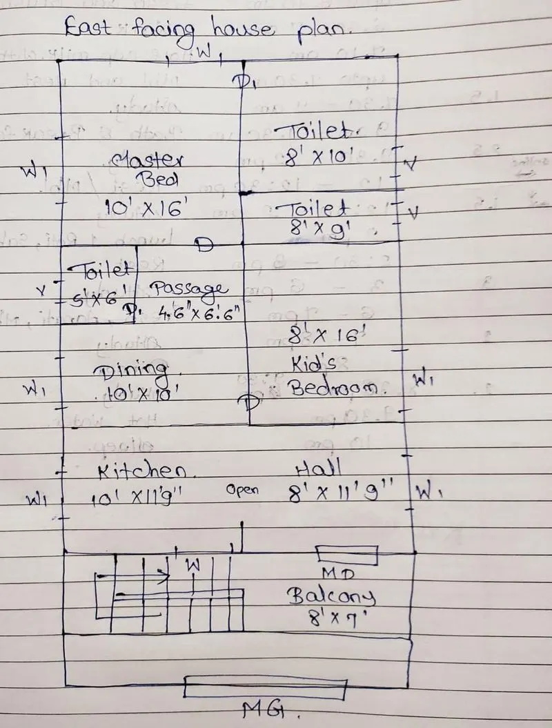
After completing anf finalizing all needful dimensions of paper , lets open new file on autocad and proceed step by step as following .
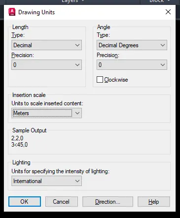
step 1: Open new file in autocad and set limits and the units .
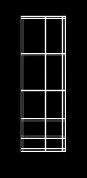
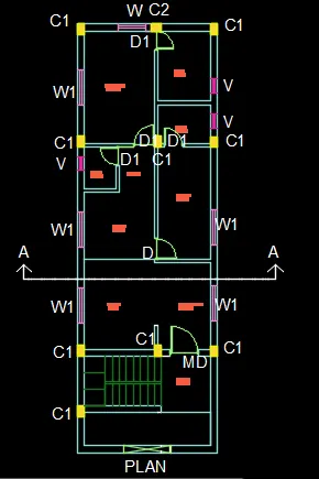
Step 2: Draw plan by using line , offset commands draw the plan
internal wall thickness 0.15m and external wall thickness 0.3 m. other offsets are as per room dimensions.
step 3: using trim command mark door and window space and remove unwanted joints.
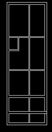
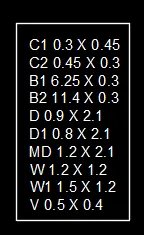
main door = 1.2 X 2.1
D = 0.9 X 2.1
D1 = 0.8 X 2.1
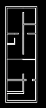
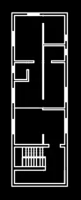
step 4 Put various items in particular layers and put name and dimension as text.
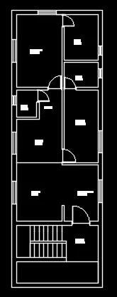
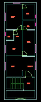
step 5 : lets put the columns on there respective place.
column sixe is 300 mm x 450 mm
i.e. 0.3 m x 0.45 m
by using rectangle command we draw the column and put it in proper place , creat one seperate layer for column
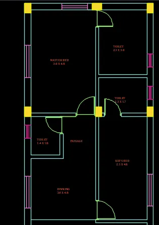
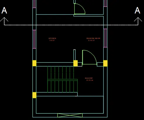
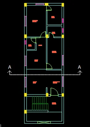
step 6 plan it completed lets move towards section.
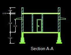
section line AA is drawn on plan
By using line commmand 3m height line drawn and then by using offset command as per size of room visible walls are drawn.
internal wall offset of 0.15m and external 0.3m other offset for toilet wall is 1.4 m , middle wall is of 3m and last outer is of 2.5m

step 7 footing are provided on outer wall
by using line and mirror command.
one footing section is copied and placed on another wall.
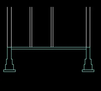
step 8
parapet wall and slab is drawn , the slab thichness is given by offset 0.15m and parapet wal height id 0.9 m
each object is put in particular layer properly.
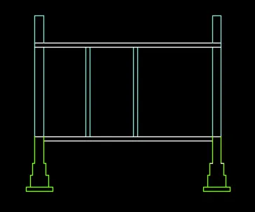
step 9
visible doors are drawn and chajjas are provided
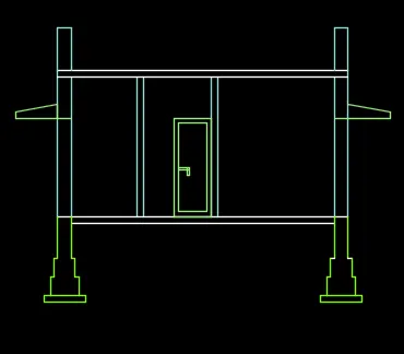
step 10
by using hatch walls are shown and using dimension height of level shown
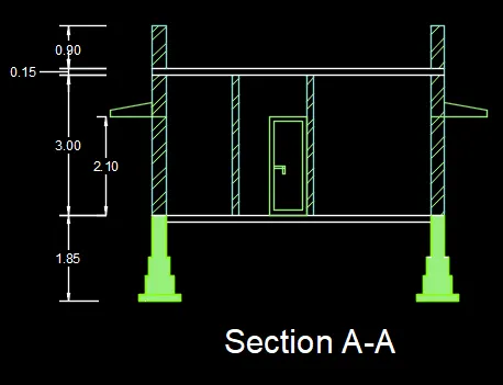
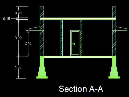
step 11
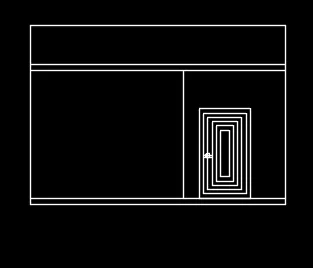
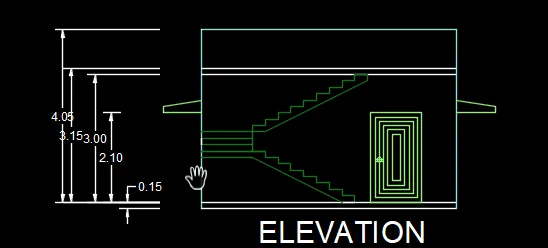
Now move towards elevation projection are taken from wall and visible objects

step 12
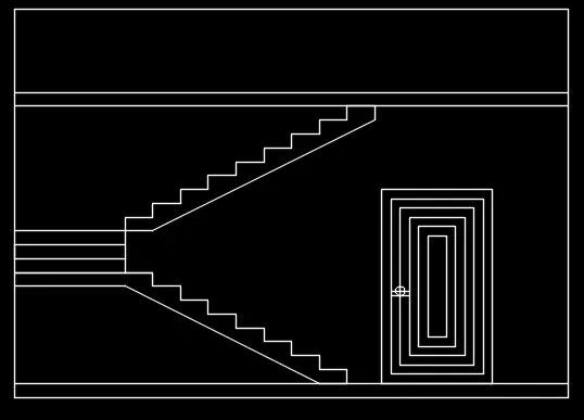
steps are drawn by taking projecton and line ,copy commnad used
riser 0.15m and tread 0.3 m
step 13
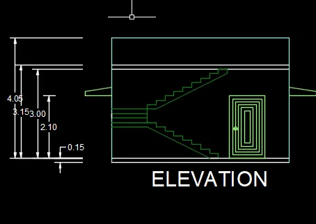
all objects are put in respective layers and height is shown by using dimension command
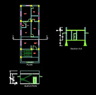
step 14 plan section and elevation and drawn .
step 15
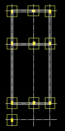
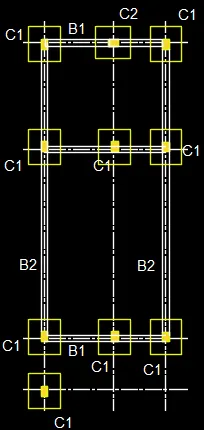
Now for structural plan we will take projection of walls or simply but keeping only wall layer on copy it .
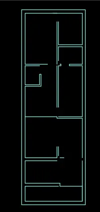
step 16 center line is drawn by refering wall
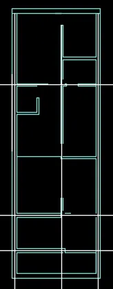
step 17 now wall are deleted and columns , beams are placed
column size 0.3 x 0.45 and 0.45 x 0.3
beam is ob sixe 3 x 0.3 and 2.5 x 0.3
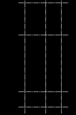
step 18 now column and footings are placed
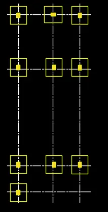
step 19 Beams are provided
Step 20
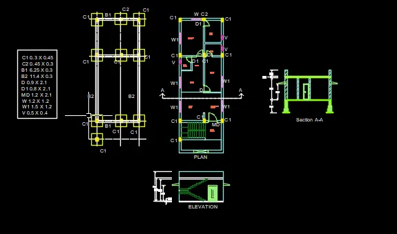
All final drawings are here
---------------------------------------------------------------------------------------------------------------------------
PLEASE FIND ATTACHED FILE NAMIMG AS CHALLENGE 8
---------------------------------------------------------------------------------------------------------------------------