Project 1 _Creating an Architectural plan for the provided plot size and develop relevant basic structural drawings
AIM-
Design and Draft a layout of a residential building with the following details:
a. Plot Size: 60’x20’(18.3m x6m)
b. Orientation- Facing East
c. Develop the following: 1. Architectural Drawing (Floor Plan, Elevations, and Sections) 2. Structural Drawing (Column, Bean, Footing Plan)
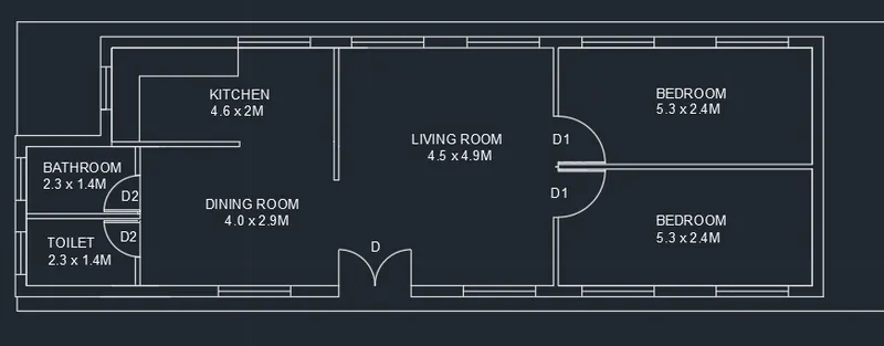
- Open new drawing
- Type command UN
- Set unit as decimal
- Precision as 0.0
- select rectangle from top ribbon menu
- draw a rectangle of 18.3x6m
- now select line from the top ribbon menu
- draw external walls of 0.2m using line tool and offset command
- draw internal walls of 0.1m using line tool and offset command
- draw doors using circle ,line , trim command
- trim any additional parts
- draw window of size 1.5x1.5m
- draw vent of size 0.5x0.9m
- Add text right click and select properties and set height to 0.2m
- Draw arrow shows diection
- Main door is facing east direction.
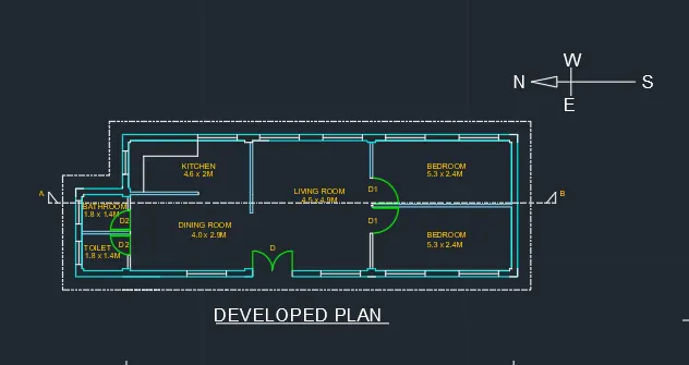
- Go to ribbon menu
- select layer properties
- click on new layers for external wall,internal wall, doors, windows, vent and select colour as required.
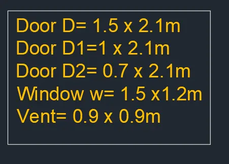
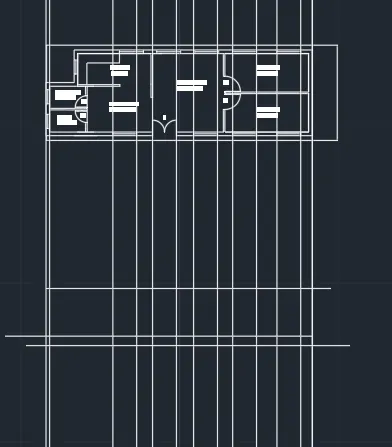
- Now to draw elevation reference lines are marked
- From the ribbon menu construction line is drawn parllel with the refernce to developed plan.
- Draw a horizontal line
- from the ribbon menu select offset command
- set offset at 0.6m,3m,0.20m for plinth , room height upto ceiling,slab thickness.
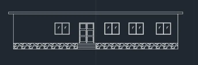
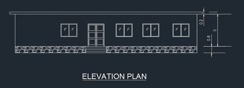
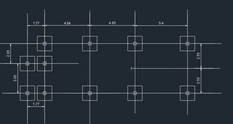
- For the column and footing plan refer develpoed plan
- Type REC command draw 0.30x0.30 column
- With copy command provide coumn at each corner
- Type REC coomand and draw 1.5x1.5m footing
- copy and provide footing below each column
- Select linear dimension and provide center to center distance of the column.
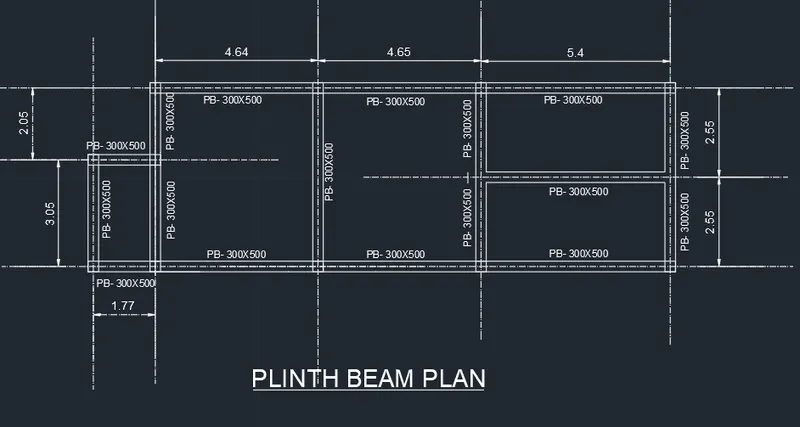
- For the plinth beam
- using line tool draw horizontal and vertical lines
- provide beam of size 300x500mm below each wall
- gow to annotate option and from the ribbon menu select centerline
- provide center line of the beam
- using linear dimention tools provide center to center distance of the plinth beam
- To draw section plan
- Draw line A B on the developed plan where you want to show the section
- using construction line draw parallel line refering to develped plan and the elevation plan
- draw internal walls, external walls
- using hatch tools to show walls, concrete, soil, dado tiles
RESULT:- Using various autcad tools architectural plan, structural plan is drawn for the given plot area