Project 1 _Creating an Architectural plan for the provided plot size and develop relevant basic structural drawings
AIM:Design and Draft a layout of a residential building with the following details:
- Develop the following: 1. Architectural Drawing (Floor Plan, Elevations, and Sections)
- 2. Structural Drawing (Column, Bean, Footing Plan)
- Layout
INTRDOUCTION:
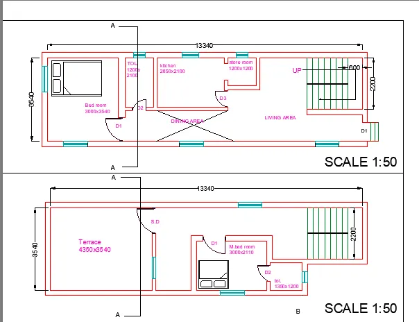
- Plot Size: 60’x20’(18.3m x6m)
- Orientation- Facing East
- taking exterior wall thickness as 230 and partition wall 150.
- assuming door and window dimenisons
door type width height D 1000 2100 D1 700 2100 D2 900 1700 S.D 1200 2100 window type Width height W2/W 1000 1200 W1 750 1200 W4 500 600
COMMAND USED:
line,trim,offset,extend,arc,rectangle,block,dimension,hatch,text,annotation,layers,layout and plot.
PROCEDURE:
- start new drawing sheet ny crtl+N-select metric.
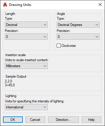
- enter UN for unit command and set as decimal-millimeter.
- enter limax and set as 3000,3000.
- to set page-enter zoom-all.
- select line and enter fisrt value as 18300 at cursor right side.
- next coordinate as 6000 towards up.
- next coordinate as 18300 at cursor left.
- click on close command.
- as per bylaws,leave offset of 2000 at left,1000 each at north and south,2500 in east.
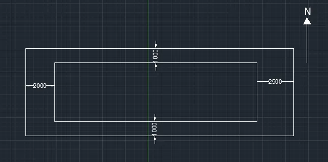
- in propsed area,offset 230 all sides as exterior wall.
- offset as per required area dor different units.
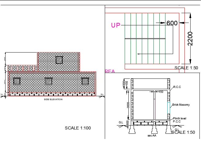
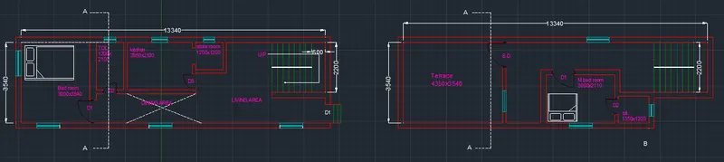
- for stairs,tread=250 and rise=150,overall width 2200 and landing area 600.
- for doors,use rectangle and arc(start,end,direction).
- enter B for block command,name as D1 select the door let it retain and specify base point in window.
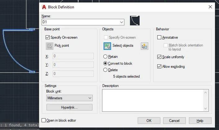
- enter I for insertion of block,select the D1 and enter.
- use scale command refernce to reduce the door size as per required width.
- similarly for windows,use lines and rectangle.
- use text command,set the height and rotation.
- use linear dimension command for measuring.
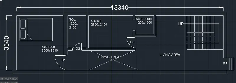
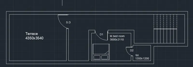
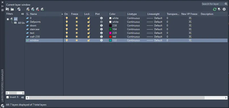
- set the layers for different properties like text,window etc from layer property.
- add section AA .
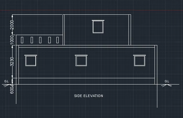
- for elevation,drag all the lines from 1st floor and 2d floor including windows.
- trim off unwanted lines.
- offset 600 as grade slab.
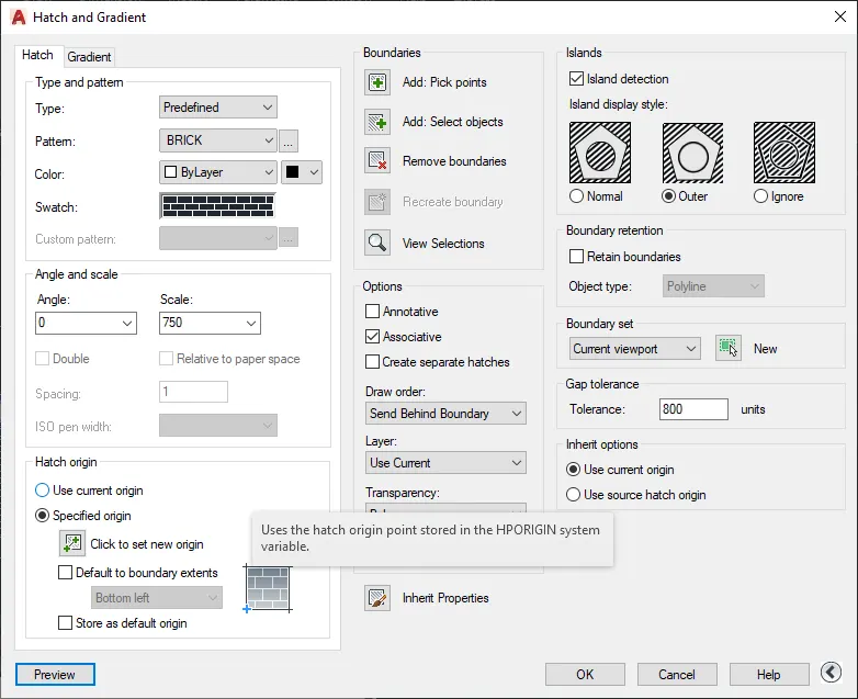
- for hatch portion,select brick pattern for wall.
- ANSI136 for windoe glazing.
- brickstone for grade slab.
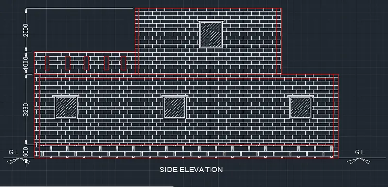
- simialry follow the same for sec AA.
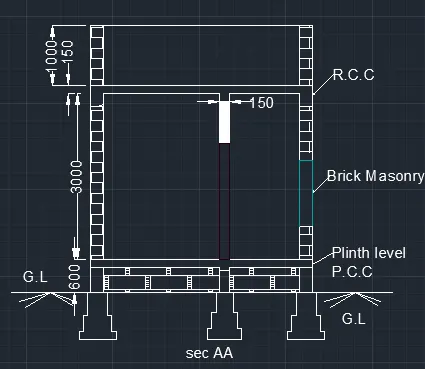
STRUCTURAL DRAWING:
- column size be 230x230 and footing 750x750.
- use rectangle and line command.
- for column making,draw line passing through center of the column.
- label the marking as 1,2-5 in y-axis and A,B-D in x-axis.
- for footing use rectangle command.
- use ASO-2W100 line type as for marking purpose.
- use mleader-block command for naming the marking.
- use dimension and text command.
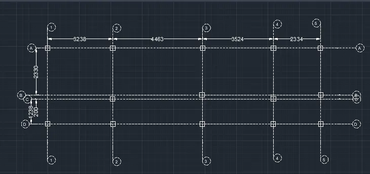
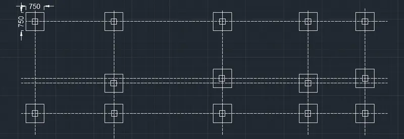
for column reinforcement making:
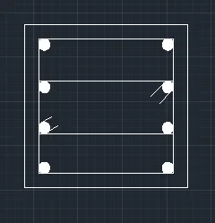
- draw a rectangle of size 230x230.
- offset 40 as column cover.
- divide the rectangle into 3 equal part.
- for bars use 16 diameter using circle with diamter.
- use hatch-solid for bars.
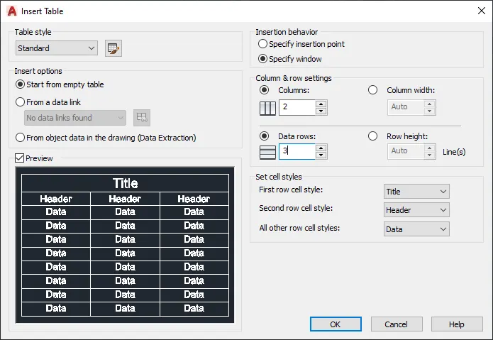
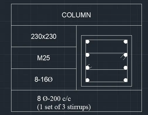
- use a table command,make a column=2 and row-4.
- enter the data using mtext command.
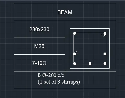
for beam reinforcement
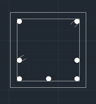
- draw a rectangle of size 230x230.
- offset 30 as a cover thickness.
- use circle with diamter to make bar,enter diamter 12.
- use hatch-solid fot bar.
- use a table command,make a column=2 and row-4.
- enter the data using mtext command.
for making of layout-
- set the page as A4.
- enter Mv and set the boundry-enter.
- use MS command to set the view.
- lock the view to amintain the scale.
- use PS for exist from MS command.
- use mtexet to enter the scale value.
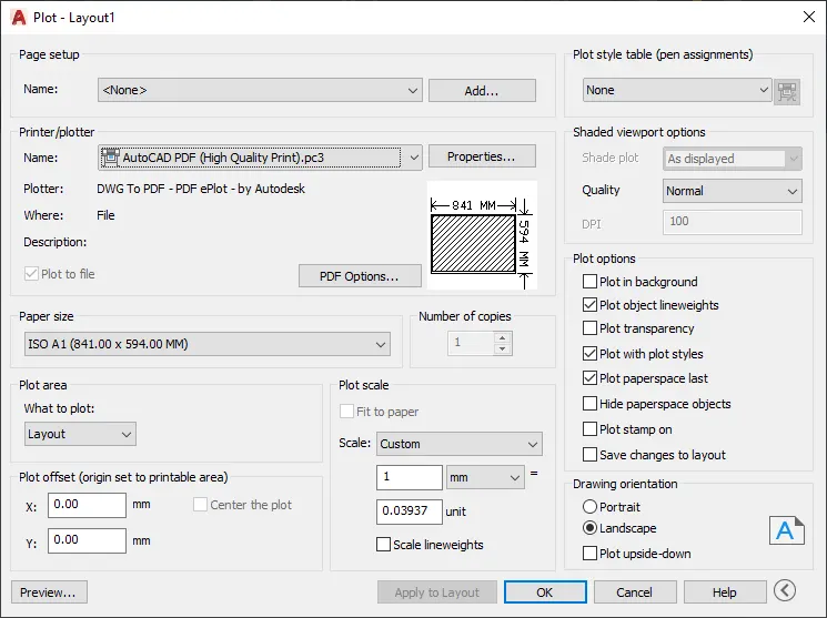
- for plot-enter PL command,set the format and preview.