Creation of Multiple viewports, Scaling the drawing and setting in Template in AutoCad
Q1- Create a layout of the Plan and Section A of the project in Challenges 7, using the template Tutorial-mArch.dwt in a scale as given in the Figure. Use the MV command to create the viewport of the size as shown in Figure. Also, use ATTEDIT command to edit the information in the title block. Use A1 size for the layout. Take a plot
AIM:
To create a layout of the plan and section A of the project in challenge_7 with A1 size paper layout, Using the template Tutorial-mArch.dwt in a scale as mentioned in a figure.Then use MV command to create the viewport of size as shown, Also use ATTEDIT command to edit the title block.
INTRODUCTION:
LAYOUT:
- Layout is the working space for creating drawing sheets and to represent drawing sheet the layout area (paper space area) displays scaled views of model space drawings with in the boundaries called viewports
- After finishing a drawing in model space at full size, we can switch to a paper space layout to create scaled views of the model space drawings, and to add notes, and annotations
- We can also specify different linetypes and line widht for display in paper space
- We can represent the drawing the drawing with several viewports, showing different area of model
- Multiple layouts tab can be used to display the details of various components in drawings varying scales and sheets
- We can also set the different layer properties for each viewport
CREATING LAYOUT VIEWPORT:
- Click on the layout which shown in bottom of screen along with modwl space, create the new layout by clicking the add icon then select it and right click then select the rename option,Rename the new layout
- Then use MV command to create a new layout viewport, Specify the view that you want to display in it with one of several methods.
- Click the corner of the rectangular area drag it downwards and the extends of model space are displayed automatically
MODEL SPACE:
- A model spce is a space which we will used to create drawings, we initially do thw work on model space, it is an area where 2-dimensional and three-dimensional entities based on ucs or wcs
PAPER SPACE:
- Paper space is where we load out drawings into a desired size papper like A0,A1,A4 etc , here we scale the model space to a paper space
- The paper size is selected based on our drawings units which is in millimeters or inches
SCALE:
- It enlarges or reduce selected objects in the object should get more closed when as the scale gets reduced
- Scaling is done to make drawing clearly visible and more details in drawing can be seen while scaling
LOCK:
- To create a lock viewport that fits the screen model space it prevent unneceaasry movement of drawing once the scale is seted
- It is advised to set a model space to lock when we finished with our scaling
XREF:
- Xref is a external reference, As the name it self shows we externally refering a particular named .dwg file to a current drawing and can bind with new drawing, Explode it and can be edited
PLOT:
- Command:Plot or in Application menu bar > Print > Plot
- A dialog box which showing the name, paper size, pen assignment etc are set.
PROCEDURE:
STEP1
- In command prompt type Units > set to decimal > precision-0 > units-millimeters
- Type limits in command box and set 0,0 as lower limit and 12000,12000 as upper limit
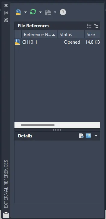
- Then save the dwg file as Challenge 10_1 and then use command "XREF" and click on attach file and attach the CH-7 diagram file
STEP2
ATTACH DWG AND BIND:
- Open the dwg file from the external reference click on the attach dwg and attach CH-7 diagram 1 file
- Here i have attached 2 drawing file one is plan and other is section-AA file seperately
- Click on the kitchen layout and "Attch external reference" dialogue box will appear click on okay
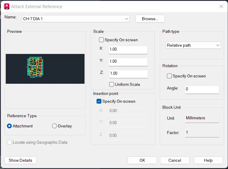
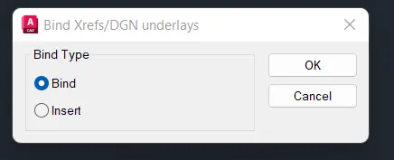
- Then go to xref tab and click on the CH-7 DIA 1 diagram right click on it then select Bind option to bind with current drawing
- Similiarly bind the CH-7 DIA 2 as well
- Place the two objects plan and section-AA on the current drawing , By using command "EXPLODE" the drawing is exploded and edited
STEP3
SAVING THE PLAN-SECTION
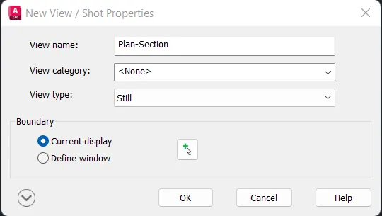
- First we have to save the view of the drawing go to View tab > new view > filename
- Type the name that you want to save as Plan-section
- Likewise save the plan and the section for further reference
STEP4
CREATING DRAWING TEMPLATE:
- Click on the layout tab right click it and create a new layout, Remane the layout as Plan and section
- Delete the current viewport displayed in the layout
- To Create a template Right click on layout then go to template or command "LAYOUT" a "select template from file" dialogue box will open Select template(.dwt) the Tutorial-mArch and press ok
- From the dialogue box,select ISO A1 layout and rename it as plan and sections
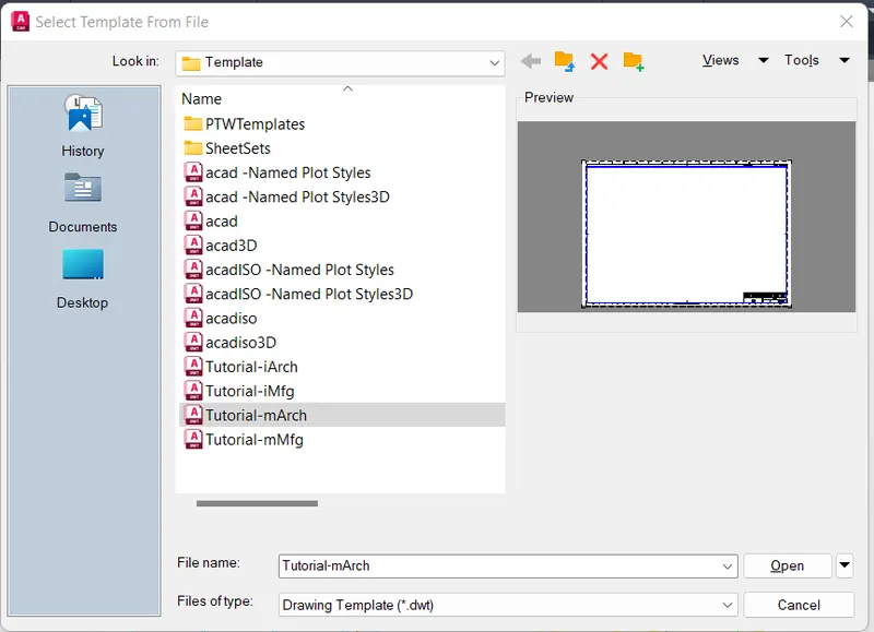
- Now the template page is created along with A1 sheet
- Then in command prompt type "MS" to go to model space
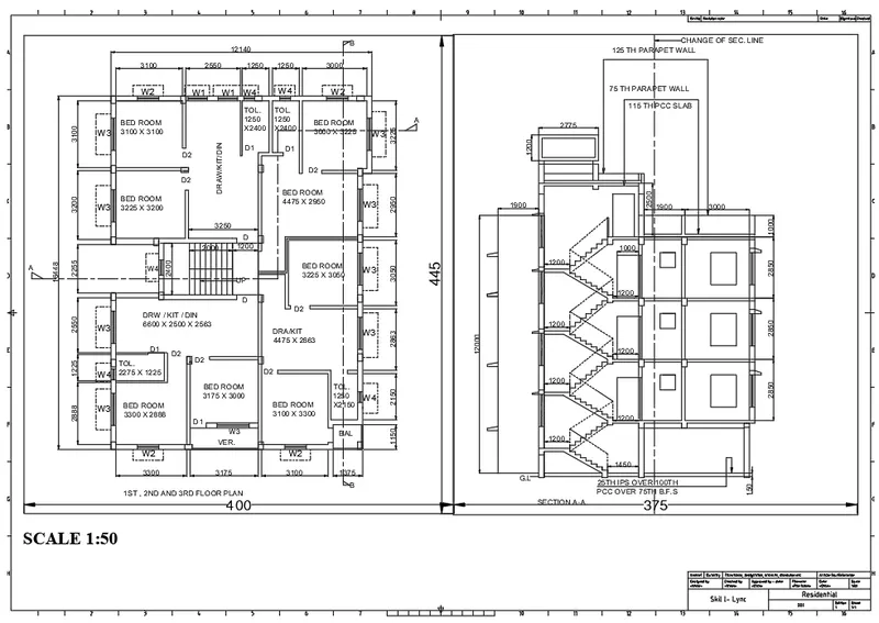
- To create a viewport command "MV" and create a rectange from right corner with dimensions of 400 x 445 and 375 x 445 a viewport boundary is created
- Then by using command "DIMLINEAR" made the dimension as shown below
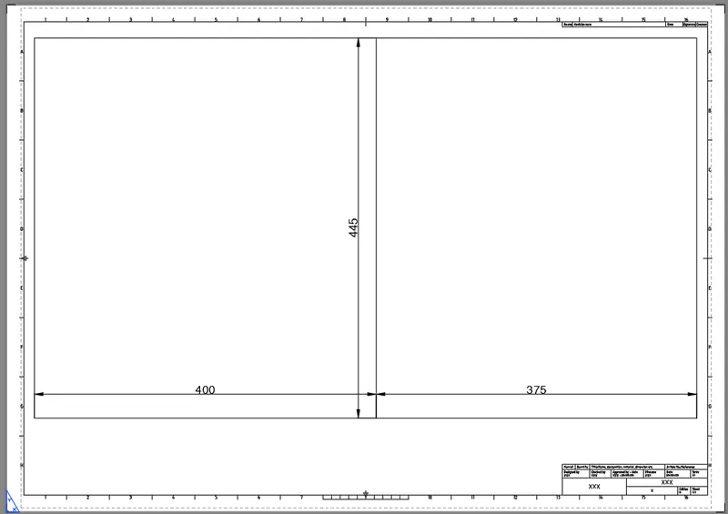
STEP5
LOADING VIEWPORT:
- To load the viewport with diagram command"MS" to model space and then command "MV" > select object > click on first rectangle. the view which we save is loaded in first rectangle
- Similarly to load second viewport with diagram command"MS" to model space and then command "MV" > select object > click on second rectangle. the view which we save is loaded in second rectangle
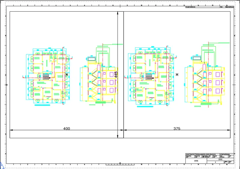
- Command "MS" for model space then we need to set the plan of CH-7 in first rectangle box
- Using "PAN" command set the plan exactly inside the first viewport and set the scale to 1:50 adjuss the drawing to fit exactly middle of rectangle box
- Once the scale is fitted the model space should be locked so that to prevent unnecessary movement as it affect the scale
- To lock the first viewport command "MV" > lock > on > select object > enter, the viewport is now locked
- Simliarly for second rectangle,
- Command "MS" for model space then we need to set the section-AA of CH-7 in first rectangle box
- Using "PAN" command set the plan exactly inside the second viewport and set the scale to 1:50 adjuss the drawing to fit exactly middle of rectangle box
- Once the scale is fitted the model space should be locked so that to prevent unnecessary movement as it affect the scale
- To lock the second viewport command "MV" > lock > on > select object > enter, the viewport is now locked
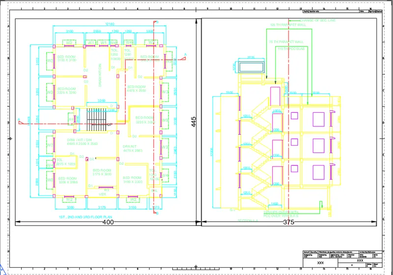
STEP6
EDIT TEMPLATE:
- Then we have to edit the attribute in template by uusing "ATTEDIT" command
- Go to paper space by command "PS" and click on the template which is a block, Click on the attributes and edit the attributes-double click the attribute text or command "ATTEDIT" the attribute dialog box appear
- Type the vale Name, Date, Title, Filename, Designed by etc.
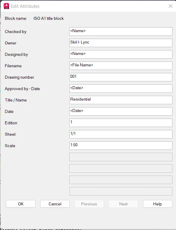
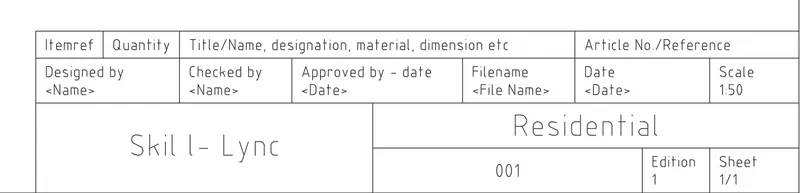
- Click on ok tab and then check the template wheather the changes you made is applied in template or not
- If not then again go to "ATTEDIT" and change the values as per requirements
STEP7
PLOTTING:
- Enter the text by using "MT" command with font style-Times new roman and text height as - 20 and write the text as SCALE 1:50
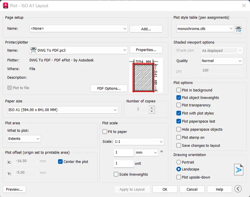
- By using command "PLOT" the drawing is taken out in A1 sheet
- Command "PLOT" a dialogue box appear set the name to - DWG to PDF, Select paper size as - ISO A1 (594 x 841mm)
- Select what to plot as- Extent and orientation given as - landscape,
- Set pen assaingment to- monochrome so that the orint wil be in lack.
- After setting all the values see the preview and click ok, the preview plot before saving it as a reference pdf file is shown save the pdf file.
RESULT:
Layout is created using template m-Arch.dwt.Viewport is created using MV command of size 400x445 and 375x445 and scale of view port is set to 1:50
Attributes in the template are edited and plot is taken using A1 size sheet
Q2-Create a layout of the Kitchen drawn in Challenge 9 as shown in Figure. Use the scale as shown in the Figure. Use A4 Size page for the layout. Take a plot
AIM:
To create different view of kitchen layout in model space, and create layout with four equal viewport,with A4 sheet, then create a plot of the drawing
PROCEDURE:
STEP1
- In command prompt type Units > set to decimal > precision-0 > units-millimeters
- Type limits in command box and set 0,0 as lower limit and 12000,12000 as upper limit
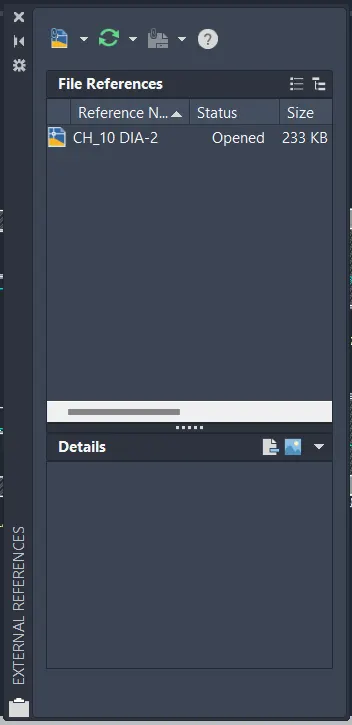
- Then save the dwg file as Challenge 10_ DIA-2 and then use command "XREF" and click on attach file and attach the CH-9 diagram file
STEP2
ATTACH DWG AND BIND:
- Open the dwg file from the external reference click on the attach dwg and attach CH-9 diagram 1 file
- Click on the kitchen layout and "Attch external reference" dialogue box will appear click on okay
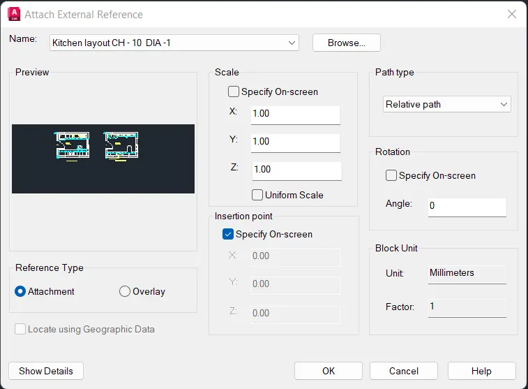
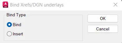
- Then go to xref tab and click on the CH-10 kitchen layout diagram right click on it then select Bind option to bind with current drawing
- The kitchen layouts binds with the current CH_10 drawing place it and by using "EXPLODE" command the kitchen layout is exploded and can be edited
STEP3
SAVING THE KITCHEN LAYOUT:
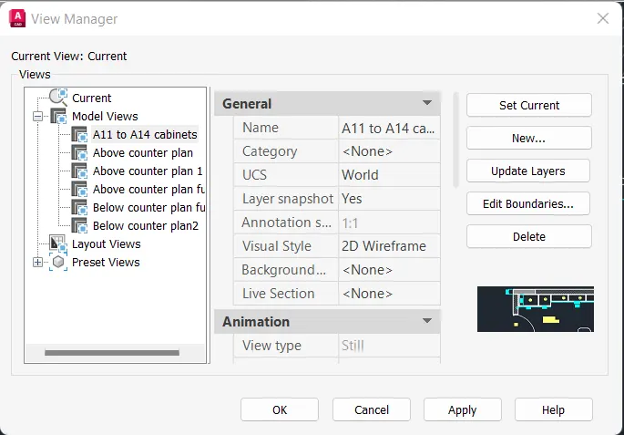
- First we have to save the view of the drawing go to View tab > new view > filename
- Type the name that you want to save as Above counter plan 1
- Likewise save the other views of kitchen layout with different names as Below counter paln 2, Above counter plan full, Below counter plan full etc
- We can see the saved view in view tab by clicking respective saved names
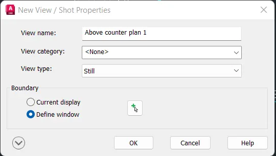
- The saved kitchen plan is showed in view manager select any one of them and set current
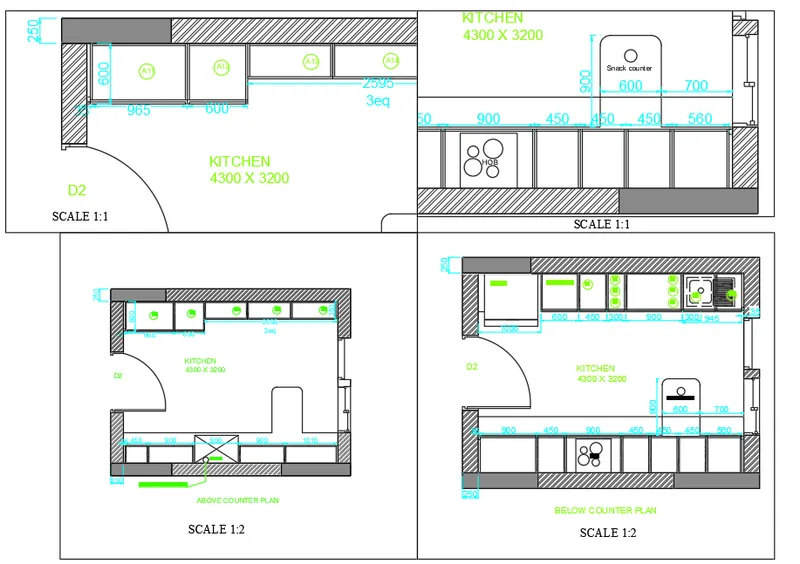
- Each view port has different layout the first view port has A11 to A14 cabinets, and second viewport has Below counter plan 2 etc
- Click on ok and the view with name above counter plan full selected drawing will be created. similarly create for below counter plan full.
STEP4
LOADING IN VIEWPORT
- First select A11 to A14 cabinet in the first viewport , Zoom it and using "PAN" command place the drawing exactly between the first viewports and set scale to 1:1
- Similar way for other three viewports each drawing is loaded and zoom it and pan is done set the scale to 1:1, for above and below full counter plan the scale is 1:2 is seted
- After seting the scale lock all the viewport to avoid change in scale command "MV" > lock > on > select four viewport > enter the all viewports are locked
- The default sheet size is A4
- Then go to paper scale by command "PS" and write the text as SCALE 1:1.
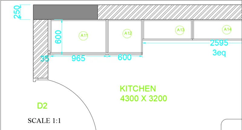
- Enter command "MS" click on th second viewport enter the command "VIEW" and select the view as below counter plan 2
- Zoom and pan the view port then lock the port by using MV command, go to paper space and with command "T" enter the text as Scale 1:1
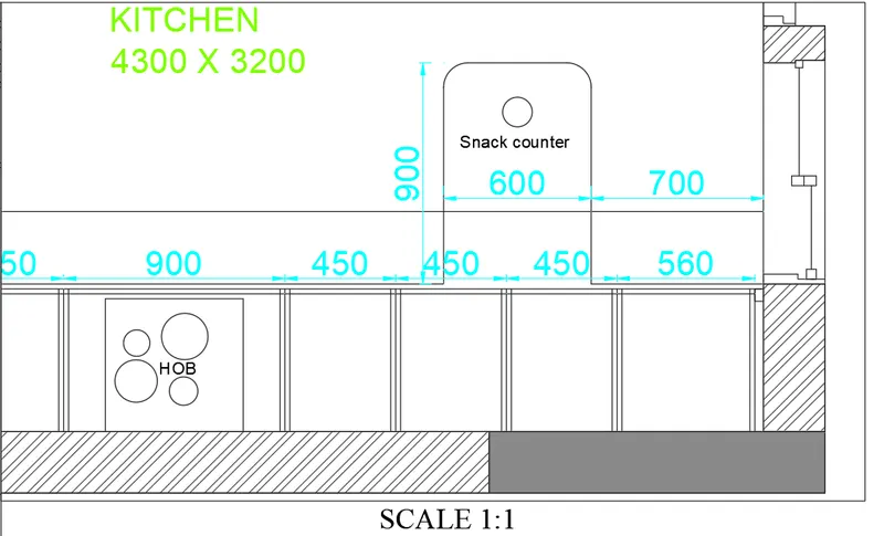
- Similarly click on third view port load the drawing as above counter plan full, place the drawing exactly to fit into the viewport and sert the scale to 1:2
- Lock the viewport "MV"> lock> on> select third viewport> enter
- Go to paper space and command "T" enter the text as scale 1:2 with text height 2 and font- times new roman.
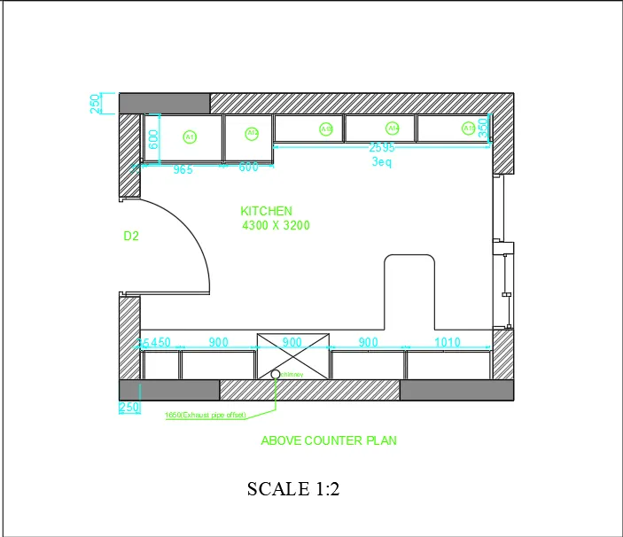
- Similarly click on third view port load the drawing as Below counter plan full, place the drawing exactly to fit into the viewport and sert the scale to 1:2
- Lock the viewport "MV"> lock> on> select third viewport> enter
- Go to paper space and command "T" enter the text as scale 1:2 with text height 2 and font- times new roman.
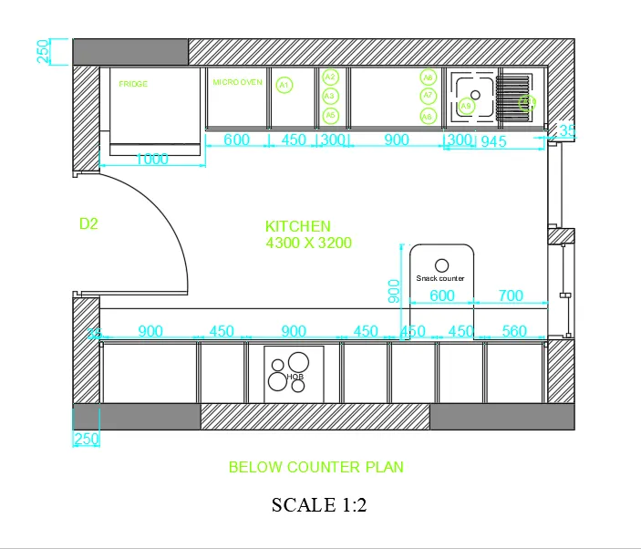
- All the viewports are locked and set to their respective scale as shown
- Now the paper is ready to print
STEP5
PLOTTING TO SHEET:
- For plotting go to application > Print > Plot
- By using command "PLOT" the drawing is taken out in A4 sheet
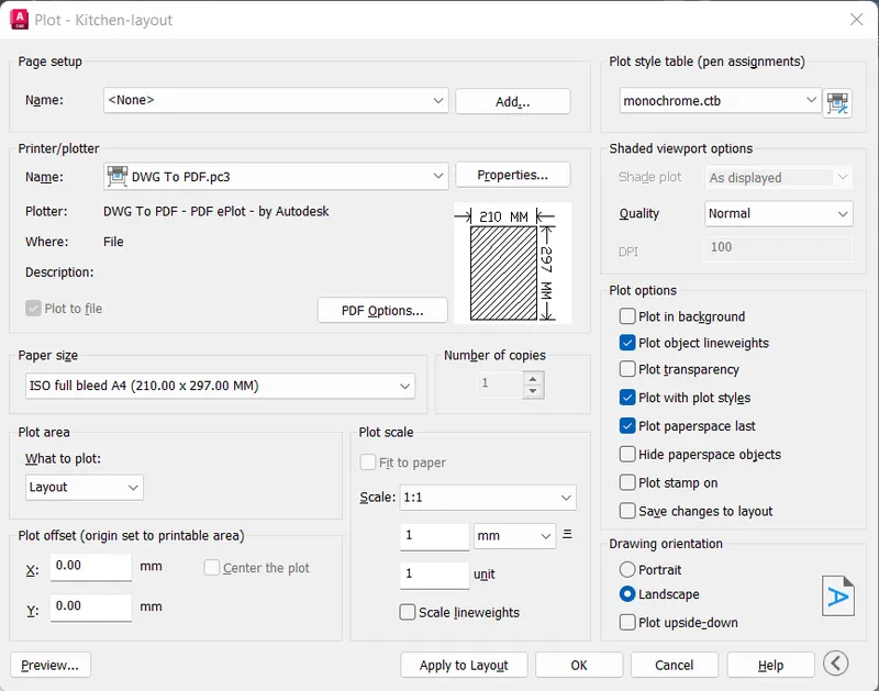
- Command "PLOT" a dialogue box appear set the name to - DWG to PDF, Select paper size as - ISO A4 (210.00 x 297.00mm)
- Select what to plot as- Extent and orientation given as - landscape,
- Set pen assaingment to- monochrome so that the orint wil be in lack.
- After setting all the values see the preview and click ok, the preview plot before saving it as a reference pdf file is shown save the pdf file.
RESULT:
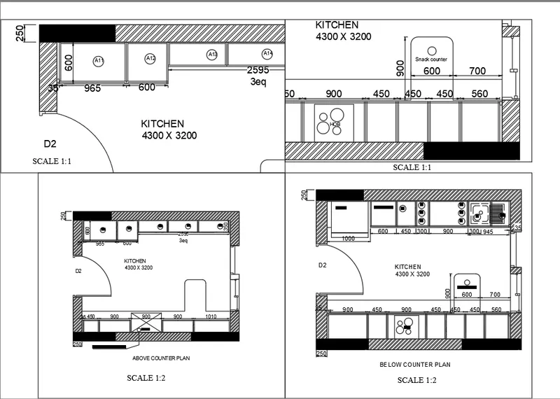
The different views of kitchen for layout in model space is created,with four equal viewports and ploted in A4 sheet.
Q3- Create a layout of the section created in Challenges 9.
Use scale as mentioned in the Figure. Use MV command create multiple viewports. Take a plot
AIM:
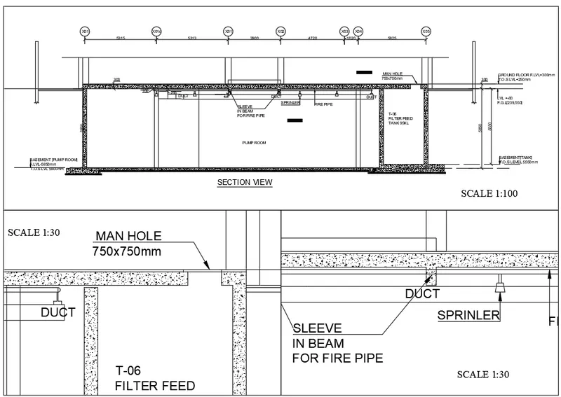
Create a layout for the section of industrial building, using scale as 1:30 and 1:100 as given, to take a plot of this layout
PROCEDURE:
STEP1
- In command prompt type Units > set to decimal > precision-0 > units-millimeters
- Type limits in command box and set 0,0 as lower limit and 12000,12000 as upper limit
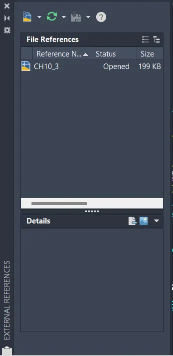
- Then save the dwg file as Challenge 10_3 and then use command "XREF" and click on attach file and attach the CH-9 diagram file
STEP2
ATTACH DWG AND BIND:
- Open the dwg file from the external reference click on the attach dwg and attach CH-9 diagram 1 file
- Click on the kitchen layout and "Attch external reference" dialogue box will appear click on okay
- Then go to xref tab and click on the CH-9 DIA 3 diagram right click on it then select Bind option to bind with current drawing
STEP3
SAVING THE PLAN-SECTION
- First we have to save the view of the drawing go to View tab > new view > filename
- Type the name that you want to save as -section
- Likewise save the plan and the section for further reference
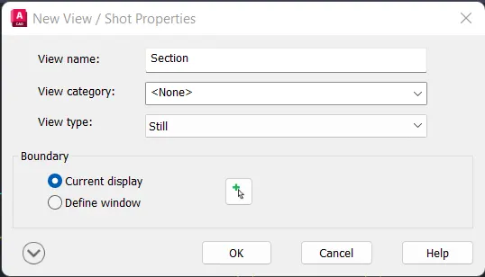
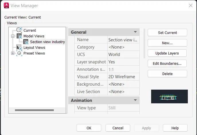
- Click ok and another tab is displayed that is view manager
- Select the file section view industry and set current and press ok
STEP4
CREATING LAYOUT AND VIEWPORTS:
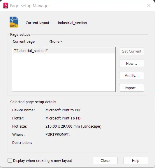
- Go to layout option and select new and type the name of the layout as -industrial section
- For creating new layout go to layout option on bottom of the screen and click add option a new layout is created rensme this layout as industrial section
- Right click on the tab and select "page set up manager" click on new give name, page set up dialogue box appears
- Then click on modify and create viewport for next two industial sectional view
STEP5
LOADING AND SCALING:
- Use command "MS" and click on the first viewport the drawing will loaded
- Adjuss the drawing and set scale to 1:100 fit the drawing into the first viewport using zoom and pan options
- Then lock the first viewport MV> lock> on > select viewport> lock
- Then go to "PS" paper space and type the text as scale 1:100 with "T" command with text height of 5
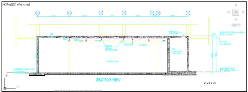
- Similarly load the drawings for other two viewports
- Use command "MS" and click on the first viewport the drawing will loaded
- Adjuss the drawing and set scale to 1:30 fit the drawing into the second viewport using zoom and pan options
- Then lock the first viewport MV> lock> on > select viewport> lock
- Then go to "PS" paper space and type the text as scale 1:30 with "T" command with text height of 5
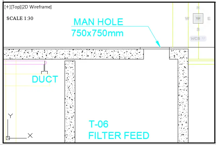
- Use command "MS" and click on the first viewport the drawing will loaded
- Adjuss the drawing and set scale to 1:30 fit the drawing into the second viewport using zoom and pan options
- Then lock the first viewport MV> lock> on > select viewport> lock
- Then go to "PS" paper space and type the text as scale 1:30 with "T" command with text height of 5
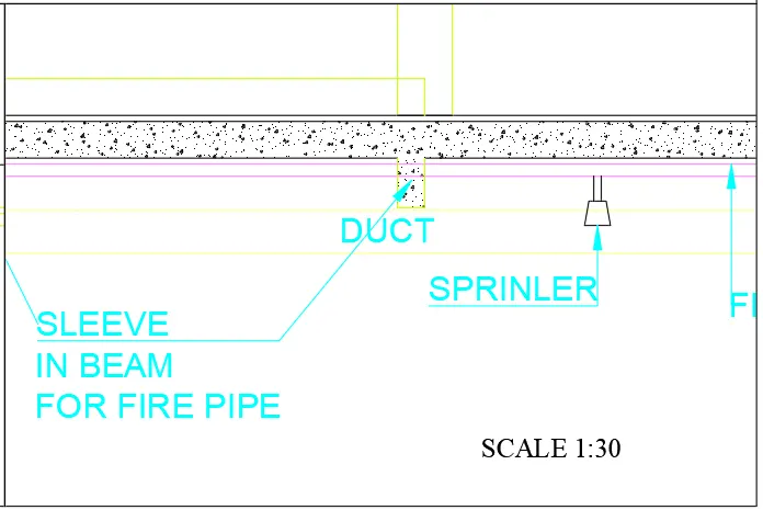
STEP6
PLOTTING TO SHEET:
- For plotting go to application > Print > Plot
- By using command "PLOT" the drawing is taken out in A3 sheet
- Command "PLOT" a dialogue box appear set the name to - DWG to PDF, Select paper size as - ISO A (420.00x 297.00mm)
- Select what to plot as- Extent and orientation given as - landscape,
- Set pen assaingment to- monochrome so that the orint wil be in lack.
- After setting all the values see the preview and click ok, the preview plot before saving it as a reference pdf file is shown save the pdf file.
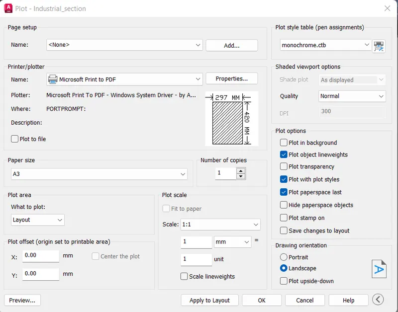
RESULT:
Layout for the industrial building is created,viewports is also created by MV command and scale is seted to 1:100 and 1:30 as shown and plot is taken.
OVERALL RESULT:
- Layout of the plan and section A of the project-7,using the template Tutorial-mArch.dwt in a scale as given in the figure is made.
- The layout of kitchen drawn in challenge 9 as shown in figure is made. scale is used as shown in figure and use A4 size sheet for layout and plot is done
- Creation of layout for industrial section in challenge 9 is made. scale is used as mentioned in figure. using MV command multiple viewports are created and then plot is made