Project 1 _Creating an Architectural plan for the provided plot size and develop relevant basic structural drawings
Aim: To create the floor plan, elevation, section and structural drawing
Introduction:
60’x20’with Vastu shastra details of residential building is given below. This is a 2bhk east-facing house plan.The floordetails are as given :the living room, dining area, kitchen, master bedroom with the attached toilet, common bathroom, and passage are available. The length and breath of the ground floor are 20’ and 60’ respectively.
Advantages of east facing house
- Wealth and prosperity are assured for the houses having east direction
- Sunlight is important to the source of natural light that brings enormous positive energies making the place vastu complaint
- A certain amount of space before the house with east-facing should be left open. It is said that the house with more space in the east is blessed with wealth and progress in life
- Main door or main gate in east ensure good result
- East facing houses is one of the best things Vaastu shastra says about. East facing house are at excellence in peace, harmony, health, wealth, name, fame, development.
Commands used:
- Line command
- Offset command
- Trim command
- Extend command
- Fillet command
- Xline command
- Dimlinear command
- Hatch command
Procedure:
Floor Plan
- Using "l" command draw the boundary of 60’x20’
- Take the size of exterior wall as 9" and interior wall as 4.5"
- The main enterance door is palced at east direction
- The floor plan is according to the vastru shastra
- The kitchen is in south east direction
- Bedroom is placed in south west direction
- After all the room placed accordingly the columns are placed according to the requeriment.

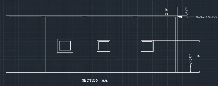
Section
- The cross section are drawn according to the floor plan
- The slab, column and window are shown
- XLINE command is used to draw the line
Elevation
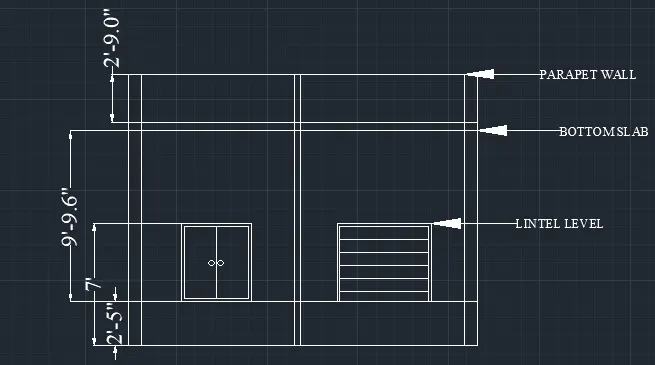
- Using "XL" command the elevation lines are drawed from the floor plan
- The outer line, column, window all are taken
- The sill level, lintel level and the parapet heighgt are all shown in elevation.
Column Layout
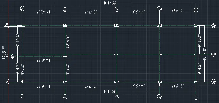
- From floor plan column alone taken and marked according to dimensions
- This drawing represents the position and orientation of columns and column reinforcement details
- Draw the dotted line from the center of the column.
Beam Layout
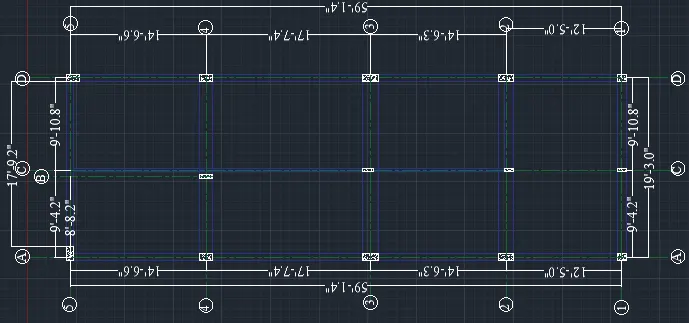
- Draw the line by connecting the edge of the column on both the sides
- Depth of the beam is calculated by D=L/A6
- Width of the beam is calculated by W=D/1.5.
Footing Plan
- The size of footing relies on different elements bearing the capacity of the soil, the number of column, totally dead and live load, and other loading and structural aspects of construction. Without knowing the bearing capacity of soil and the load coming over it, we can only determine the size of footing by the use of the thumb rule.
- In a simple ground floor building, thumb rule, utilizing standard 9″ thick walls, it is suggested that the size of column footing must be 3.5’×3.5’×3.5′ for isolated footing shallow foundation in gravel and sand soil with ultimate bearing capacity in which width dimensions is 3.5’×3.5′.
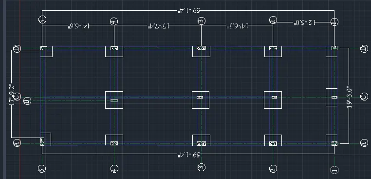
Result: The Architectural Drawing and Structural Drawing are drafted using the above procedure in Autocad.