Creation of geometries by Coordinate system methods using AutoCad
Aim : To create geometries and trusses using the coordinates system methods.
Introduction:
Coordinate system
The types of coordinate systems are:
- Absolute coordinate system
- Relative coordinate system
Relative rectangular coordinates
Relative polar coordinate
- Direct distance entry
Absolute coordinates:
Absolute coordinate entry always counts from the origin. When drawing lines, AutoCAD is ready to place the next vertex wherever you tell it to go. To locate a point using the Absolute Coordinate system, type the X-value, Y-value.
Relative coordinate system:
Relative coordinates are locations defined by their distance from a reference point.The first point are always related to origin(0,0) and the next point is always related to their preceding point.
Relative coordinate system are further classifed as:
Relative Rectangular Coordinate system:
After first points entered, your next points can be entered by specifying the next coordinate compare/relative from the first points. The relative coordinate started with symbol “@” tell AutoCAD it was a relative coordinates. Using relative coordinate, points entered by typing @x,y.
Relative Polar coordinate system:
Polar coordinates used when you need to draw the next points at specify angle. Polar coordinates system in AutoCAD specifies distance length at which angle. Using polar coordinate, points entered by typing @distance
Direct Entry Method System:
This is the most common and easiest system used for drafting in Autocad. Values are provided through keyboard and direction is guided through the mouse.
Procedure:
- Open the AutoCAD SOFTWARE
- Type startup in the command bar then press enter
- Enter the value of startup as 1
- Go to the application menu and select NEW
- Create a new drawing dialogue bar appeares in that select DRAWING
- Select IMPERIAL from the dialogue bar.
The above procedure will be fallowed for all the new drawing in autocad.
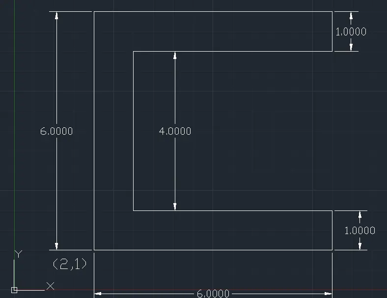
Drafting the geometry given in P1
- Using Absolute coordinate system:
- Select the line tool by entering 'Line' in the command bar
- Specify the first point as 2,1 in the command bar
- Specify the next point as 8,1 in the command bar
- Specify the next point as 8,2 and press enter
- Specify the next point as 3,2 and press enter
- Specify the next point as 3,6 and press enter
- Specify the next point as 8,6 and press enter
- Specify the next point as 8,7 and press enter
- Specify the next point as 2,7 and press enter
- Then click on close in the command bar.
2.Using Relative rectangular coordinate system:
- Select the line tool by entering 'Line' in the command bar
- Specify the first point as 2,1 in the command bar
- Specify the next point as @6,0 in the command bar (x=6, y=0)
- Specify the next point as @0,1 (x=0, y=1)
- Specify the next point as @-5,1(x=-5, y=0)
- Specify the next point as @0,4 (x=0, y=4)
- Specify the next point as @5,0 (x=5, y=0)
- Specify the next point as @0,1 (x=0, y=1)
- Specify the next point as @-6,0(x=-6, y=0)
- Then click on close in the command bar.
3.Using Relative polar coordinate system:
- Select the line tool by entering 'Line' in the command bar
- Specify the first point as 2,1 in the command
- Specify the next point as @6<0
- Specify the next point as @1<90
- Specify the next point as @5<180
- Specify the next point as @4<90
- Specify the next point as @5<0
- Specify the next point as @1<90
- Specify the next point as @6<180
- Then click on close in the command bar.
Result:The Geometry P1 is drafted according to all the coordinate system in AutoCAD
Drafting the geometry given in P2
1.Using Absolute coordinate system:
- Select the line tool by entering 'Line' in the command bar
- Specify the first point as 2,1 in the command bar
- Specify the next point as 5,1
- Specify the next point as 5,5
- Specify the next point as 6,5
- Specify the next point as 9,1
- Specify the next point as 7,8
- Specify the next point as 4,8
- Then click on close in the command bar.
2.Using Relative rectangular coordinate system:
- Select the line tool by entering 'Line' in the command bar
- Specify the first point as 2,1 in the command bar
- Specify the next point as @3,0
- Specify the next point as @0,4
- Specify the next point as @1,0
- Specify the next point as @0,-4
- Specify the next point as @3,0
- Specify the next point as @-2,7
- Specify the next point as @3,0
- Then click on close in the command bar.
3.Using Relative polar coordinate system:
- Select the line tool by entering 'Line' in the command bar
- Specify the first point as 2,1 in the command
- Specify the next point as @3<0
- Specify the next point as @4<90
- Specify the next point as @1<0
- Specify the next point as @4<90
- Specify the next point as @7<106
- Specify the next point as @3<0
- Specify the next point as @7<74.
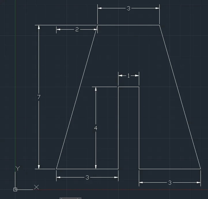
Result:The Geometry P2 is drafted according to all the coordinate system in AutoCAD
Drafting the geometry given in P3
- Using Relative rectangular coordinate system:
- Select the line tool by entering 'Line' in the command bar
- Specify the first point as 2,1 in the command bar
- Specify the next point as @1,0
- Specify the next point as @0,2
- Specify the next point as @3,0
- Specify the next point as @0,1
- Specify the next point as @-3,0
- Specify the next point as @0,3
- Specify the next point as @5,0
- Specify the next point as @0,1
- Specify the next point as @-6,0
- Then click on close in the command bar.
Result:The Geometry P3 is drafted according to the relative rectangular coordinate system in AutoCAD
3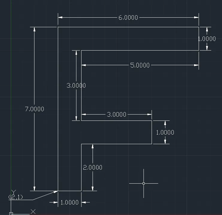
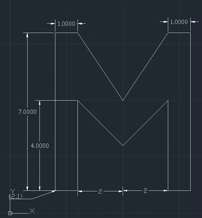
Drafting the geometry given in P4
- Using Relative rectangular coordinate system:
- Select the line tool by entering 'Line' in the command bar
- Specify the first point as 2,1 in the command bar
- Specify the next point as @1,0
- Specify the next point as @0,4
- Specify the next point as @2,-2
- Specify the next point as @2,2
- Specify the next point as @0,-4
- Specify the next point as @1,0
- Specify the next point as @0,7
- Specify the next point as @-1,0
- Specify the next point as @-2,-3
- Specify the next point as @-2,3
- Specify the next point as @-1,0
- Then click on close in the command bar.
Result:The Geometry P4 is drafted according to the relative rectangular coordinate system in AutoCAD
Drafting the geometry given in P5
- Using Relative rectangular coordinate system:
- Select the line tool by entering 'Line' in the command bar
- Specify the first point as 2,1 in the command bar
- Specify the next point as @0,8
- Specify the next point as @7,0
- Specify the next point as @0,-8
- Specify the next point as @-4,0
- Specify the next point as @0,1
- Specify the next point as @3,1
- Specify the next point as @0,6
- Specify the next point as @-5,0
- Specify the next point as @0,-7
- Specify the next point as @-1,0.
Result:The Geometry P5 is drafted according to the relative rectangular coordinate system in AutoCAD
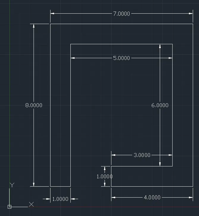
Drafting the geometry given in P6
- Using Relative rectangular coordinate system:
- Select the line tool by entering 'Line' in the command bar
- Specify the first point as 2,1 in the command bar
- Specify the next point as @4,0
- Specify the next point as @4,3
- Specify the next point as @0,2
- Specify the next point as @0,4
- Specify the next point as @-4,0
- Specify the next point as @0,-9
- Specify the next point as @3,3 (for the inside rectangle)
- Specify the next point as @2,0
- Specify the next point as @0,3
- Specify the next point as @-2,0
- Specify the next point as @0,-3.
Result:The Geometry P6 is drafted according to the relative rectangular coordinate system in AutoCAD
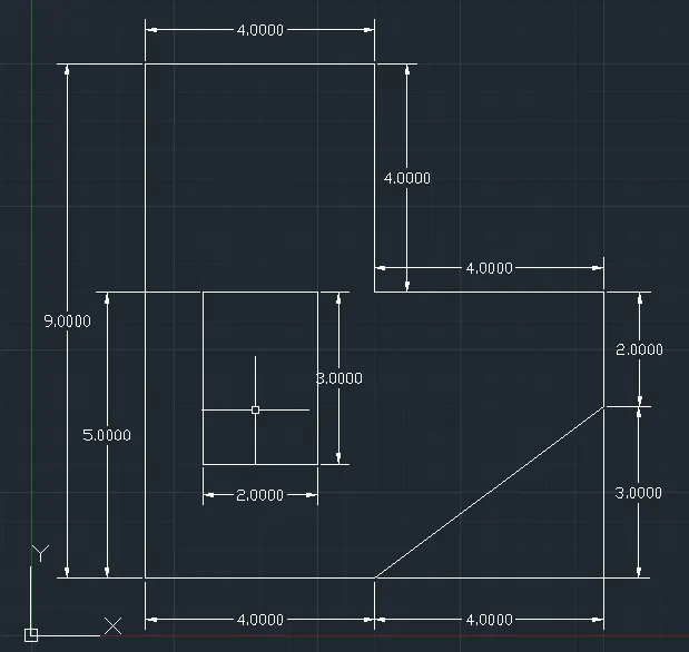
Drafting the geometry given in P7
- Using Relative rectangular coordinate system:
- Select the line tool by entering 'Line' in the command bar
- Specify the first point as 2,1 in the command bar
- Specify the next point as 8,0
- Specify the next point as 0,6
- Specify the next point as -8,0
- Specify the next point as 0,-6
- Specify the next point as 3,2 ( for the first inner rectangle take the point from 0,0)
- Specify the next point as 2,0
- Specify the next point as 0,3
- Specify the next point as -2,0
- Specify the next point as 0,-3
- Specify the next point as 6,2 (for the second rectangle take the point from 0,0)
- Specify the next point as 2,0
- Specify the next point as 0,3
- Specify the next point as -2,0
- Specify the next point as 0,-3.
Result:The Geometry P7 is drafted according to the relative rectangular coordinate system in AutoCAD.
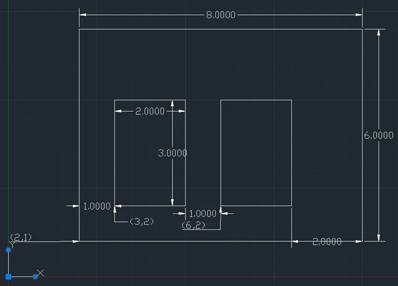
Drafting the geometry given in P8
- Using Relative rectangular coordinate system:
- Select the line tool by entering 'Line' in the command bar
- Specify the first point as 0,0 in the command bar
- Specify the next point as @10,0
- Specify the next point as @0,2
- Specify the next point as @-4,0
- Specify the next point as @0,4
- Specify the next point as @3,0
- Specify the next point as @0,2
- Specify the next point as @-8,0
- Specify the next point as @0,-2
- Specify the next point as @3,0
- Specify the next point as @0,-4
- Specify the next point as @-4,0
- Then click on close in the command bar.
Result: The Geometry P8 is drafted according to the relative rectangular coordinate system in AutoCAD.
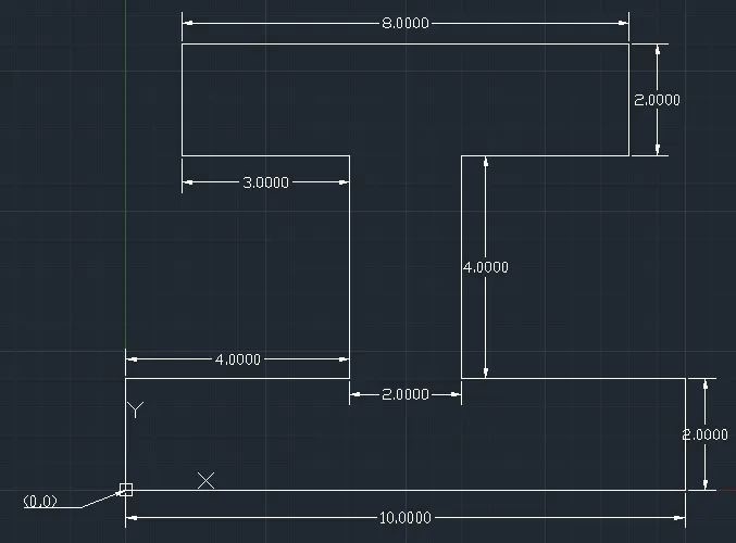
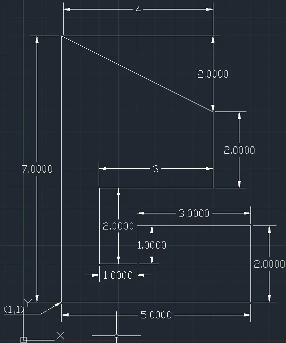
Drafting the geometry given in P9
- Using Relative rectangular coordinate system:
- Select the line tool by entering 'Line' in the command bar
- Specify the first point as 1,1 in the command bar
- Specify the next point as @5,0
- Specify the next point as @0,2
- Specify the next point as @-3,0
- Specify the next point as @0,-1
- Specify the next point as @-1,0
- Specify the next point as @0,2
- Specify the next point as @3,0
- Specify the next point as @0,2
- Specify the next point as @-4,2
- Then click on close in the command bar.
Result: The Geometry P9 is drafted according to the relative rectangular coordinate system in AutoCAD
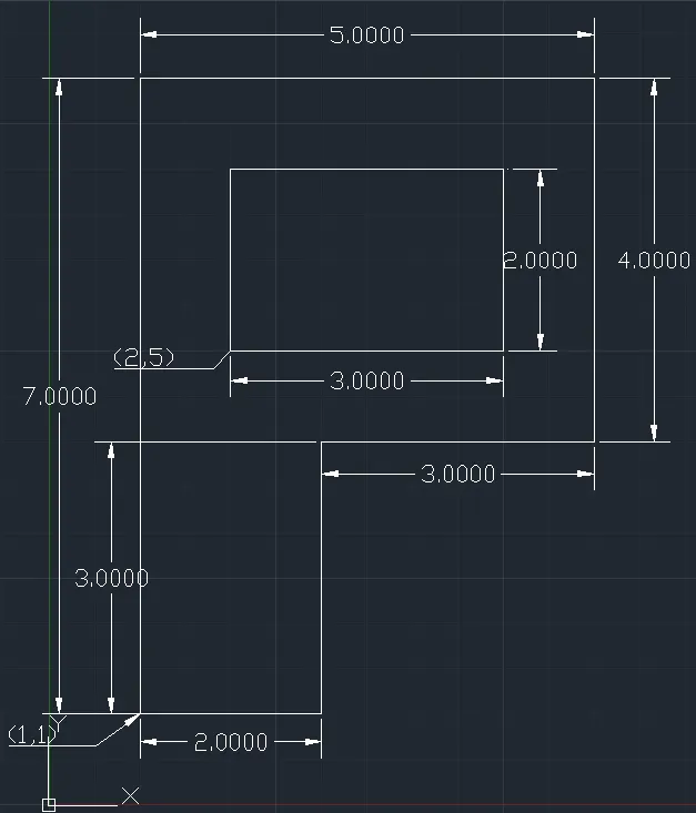
Drafting the geometry given in P10
- Using Relative rectangular coordinate system:
- Select the line tool by entering 'Line' in the command bar
- Specify the first point as 1,1 in the command bar
- Specify the next point as @2,0
- Specify the next point as @0,3
- Specify the next point as @3,0
- Specify the next point as @0,4
- Specify the next point as @-5,0
- Specify the next point as @0,-7
- Specify the next point as @2,5 (for the inner rectangle, first point)
- Specify the next point as @3,0
- Specify the next point as @0,2
- Specify the next point as @-3,0
- Specify the next point as @0,-2
Result:The Geometry P10 is drafted according to the relative rectangular coordinate system in AutoCAD
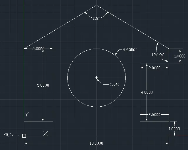
Drafting Profile - wood
- Using Relative polar coordinate system:
- Select the line tool by entering 'Line' in the command bar
- Specify the first point as 0,0 in the command bar
- Specify the next point as @10<0
- Specify the next point as @1<90
- Specify the next point as @2<180
- Specify the next point as @4<90
- Specify the next point as @2<0
- Specify the next point as @1<90
- Specify the next point as @5.831<120.96
- Specify the next point as @5.831<30.96
- Specify the next point as @2<0
- Specify the next point as @-5<90
- Specify the next point as @-2<0
- Specify the next point as @-1<90
- Specify the next point as 5,4( it is the center of the circle with the radius of 2)
Result: The Profile-wood is drafted according to the relative polar coordinate system in AutoCAD
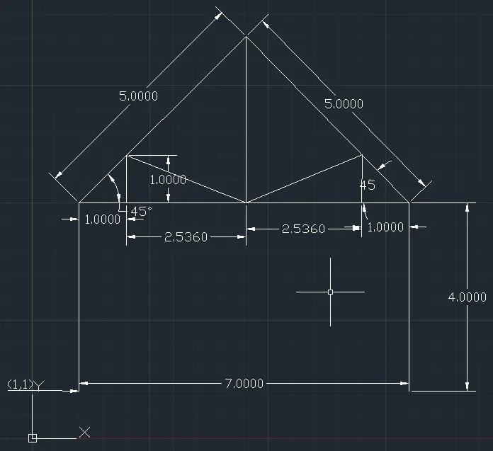
Drafting Queen post truss
- Using Relative polar coordinate system:
- Select the line tool by entering 'Line' in the command bar
- Specify the first point as 1,1 in the command bar
- Specify the next point as @4<90
- Specify the next point as @5<45(at the left side)
- Specify the next point as @3.536<90(at the left side)
- Specify the next point as @2.536<90(at the left side)
- Specify the next point as @1<0(at the left side)
- Specify the next point as @5<45(at the right side)
- Specify the next point as @3.536<90(at the right side)
- Specify the next point as @2.536<90(at the right side)
- Specify the next point as @1<0 (at the right side)
Result:The Queen post truss is drafted according to the relative polar coordinate system in AutoCAD
Drafting Mono Pitch
- Using Relative rectangular coordinate system:
- Select the line tool by entering 'Line' in the command bar
- Specify the first point as 1,1 in the command bar
- Specify the next point as @6,2
- Specify the next point as @0,-2
- Specify the next point as @-2,1.33
- Specify the next point as @-2,0.667
- Specify the next point as @6,0
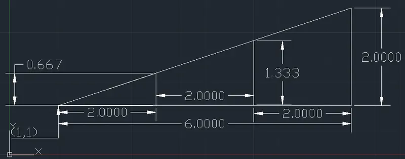
Result:The Mono Pitch is drafted according to the relative polar coordinate system in AutoCAD
Drafting Flat Truss
- Using Relative polar coordinate system:
- Select the line tool by entering 'Line' in the command bar
- Specify the first point as 1,1 in the command bar
- Specify the next point as @5<90
- Specify the next point as @7<0
- Specify the next point as @-5<90
- Specify the next point as @1,5
- Specify the next point as @1.414<45( repeat it till it reaches 7units)
- Specify the next point as @-7<0
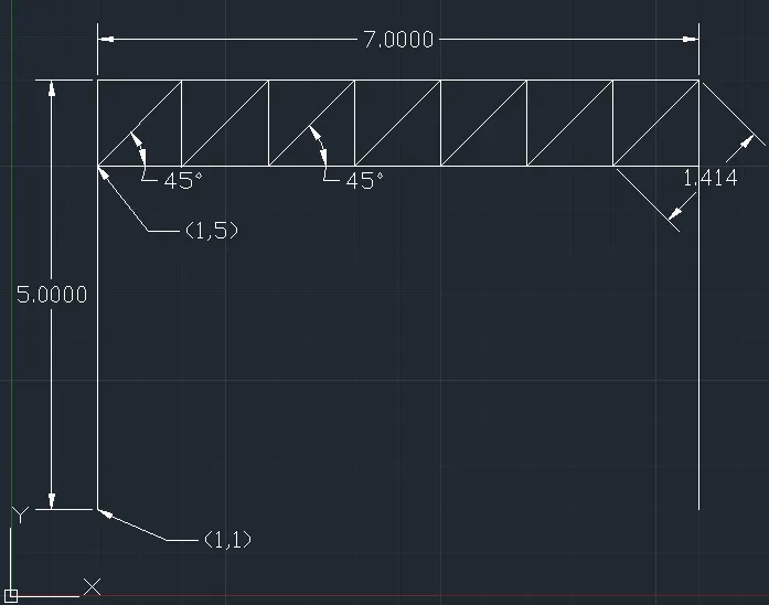
Result:The Flat Truss is drafted according to the relative polar coordinate system in AutoCAD