Project 1 _Creating an Architectural plan for the provided plot size and develop relevant basic structural drawings
CHALLENGE 08 - PROJECT01
CREATING AN ARCHITECTURAL PLAN FOR THE PROVIDED PLOT SIZE AND DEVELOP RELEVANT BASIC STRUCTURAL DRAWINGS:
AIM:
To draw:
1. Architectural Drawing of a Residential Building:
- Plan of a residential building.
- Elevation of a residential building.
- Section of a residential building.
2.Structural Drawing:
- Column plan layout of the building.
- Footing plan layout of the building.
- Beam plan layout of the building.
Commands Used:
- Line.
- Offset.
- Rectangle.
- Trim.
- Extend.
- Block.
- Block edit.
- Dimension.
- Layer.
- Hatch.
Procedure:
Step 1:
-
Opening of AutoCAD, setting limits .Select metric as we are drawing in Meters.
-
Set the limits and zoom all (Command -Z-a).Set the dimension to decimal units and set the precision.
Architectural drawing of residential building
Plan of the residential building:
Step 2:
- Drawing the plot, and giving setback.Given plot size as 18.3m x6m.Mark the direction N, S, E, W.
- By rectangle, draw the plot giving dimensions as 6 and 18.3 m.
- Give setback from the plot, 4.3m and 3m for the sides.The proposed building should come inside the setback drawn.
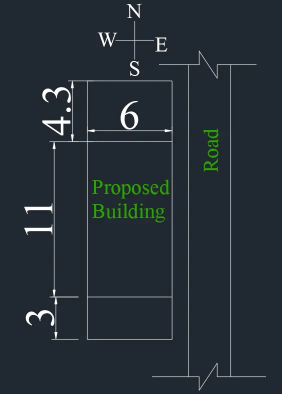
Drawing of plan:
Step 3:
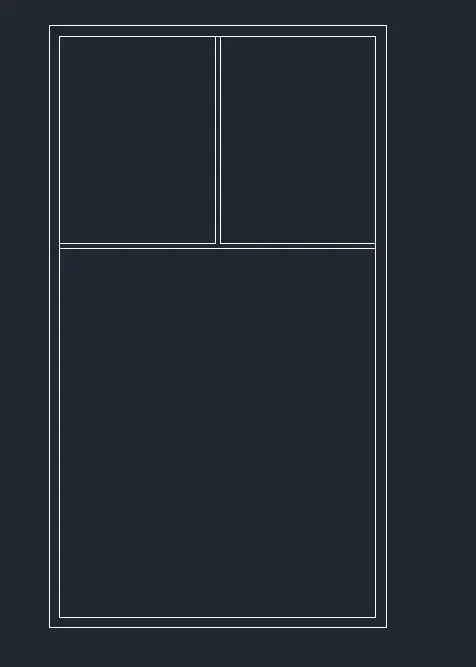
- Drawing wallOffset 0.25 m from the boundary after the setback is taken for the wall thickness.
Step 4:
Drawing Living room:
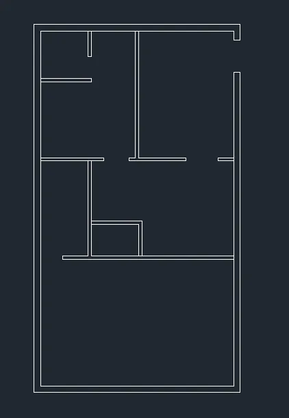
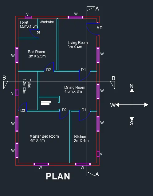
- As the orientation is given as East, main door should face East.For living room, give 3m offset horizontally from the West side.
- The size of the room will be 3 x 4 m.
- Opening for main door is create by offsetting 1.5m from the wall and trim the same.
- As per Vaastu Shastra, North-East is favourable for living room and the entrance should face North or East.
Step 5:
Drawing dining room:
- Again offset 3m from the living wall for dining room.Width will be 4.5m
- Size of dining room is 4.5x 3 m.Create a door opening of 1m on the North wall of living.
Step 6:
Drawing kitchen:
- Offset 2m horizontally from dinning wall and 4m vertically.The size of kitchen is 2 x4 m.
- Trim 1 m for the door opening.
- According to Vaastu Shastra the ideal position for kitchen is South-East ,with cooking place facing East.
Step 7:
Drawing Master bedroom and toilet:
- From the South wall offset 4m and width of 4m joining the kitchen wall.
- The size of bedroom is 4x 4m.Create opening of 0.80 m by offset and trim commands.
- For toilet, draw an offset horizontal of 1.5 m from the Dinining wall.
- Size of toilet is 1.5 x2m.
- North-East should be avoided for toilets according to Vaastu Shastra
- According to Vaastu Shastra the ideal position for Bed room is South-West.
Step 8:
Drawing of Puja room:
- From the Toilet offset 1.5m and from master bed room offset 1m.
- Size of the puja room is 1.5m x1.0m.
- North-East should be good for puja room according to Vaastu Shastra.
Step 9:
Drawing of Bed room with toilet:
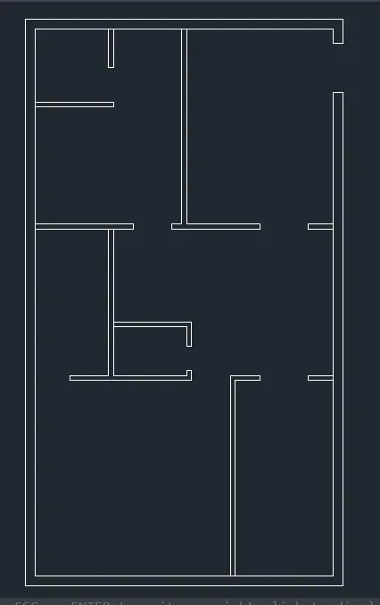
- From Living room offset 3m and from dining room offset 2.5m .Size of the bed room is 3m x 2.5m.
- Draw a toilet of 1.5m x 1.5m inside the bed room.
- Trim the excess lines and fillet the corners.
- According to Vaastu Shastra for bed room is North-East good.
Step 10:
Placing Doors and Windows:
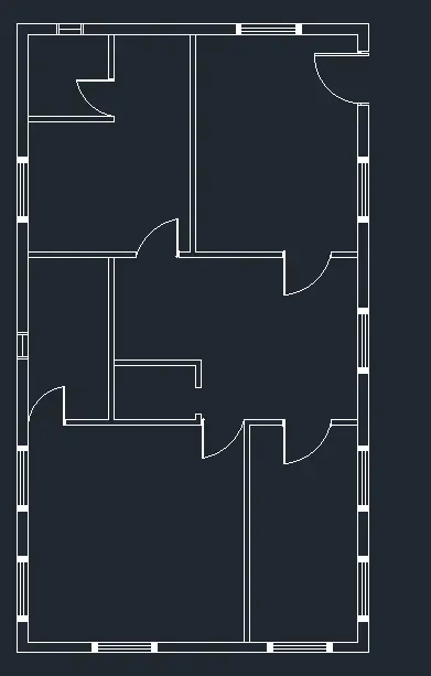
- Place the doors and windows in the respective places.
-
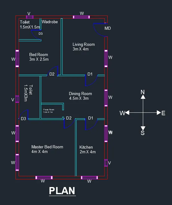
MD - 1000 X 2100mm D1 - 900 x 2100mm D2 - 800 x 2100mm D3 - 700 x 2100mm -
W 1000 x 1200mm V 600mm x 600mm
Step 11:
Use of Layer:
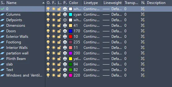
- Different layers are made and the objects are placed in layers.Click on layer, layer manager dialogue box appears.
- Create new layer button and create the layer for walls, stairs, doors, windows, text, dimension.Insert the respective elements in the layer.
Step 12:
Inserting text:
- With multiline text, draw the text box, text height as 0.15m and style as Times roman.
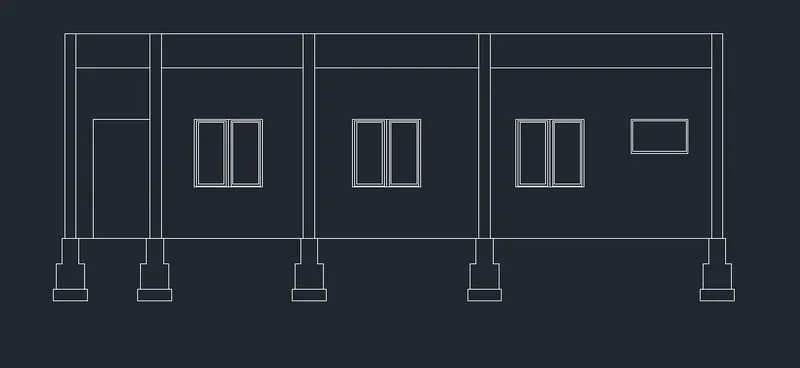
Elevation:
Step 13:
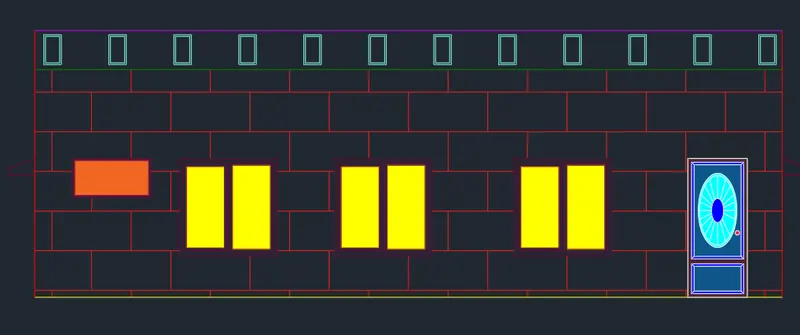
- Projecting lines to draw the elevation.Project the wall lines to the top.
- Draw a horizontal line.Offset 1 m for the plinth level.Offset 2.1m for the Lintel level.Offset 3.5m for the floor level .Offset 0.6m for the parapet wall.
- Trim off the extension lines and make shutters and panels for doors and windows.
- For architectural purpose, create some hatches.
Sections:
Step 14:
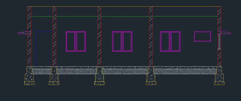
SECTION A-A:
- Project the lines from the elevation for the height and from the section line of plan for the horizontal members.
- Drawing windows, doors and stairs in section.Draw the window and door which we see after cutting the section line.
- Trim off the unawanted lines.
Step 15:
Hatching and layering:
- Using hatch hatch the walls with the bricks hatch and foundation with the concrete hatch.
- Place the windows and foundations in the respective layers and give colours.
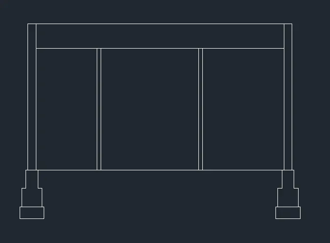
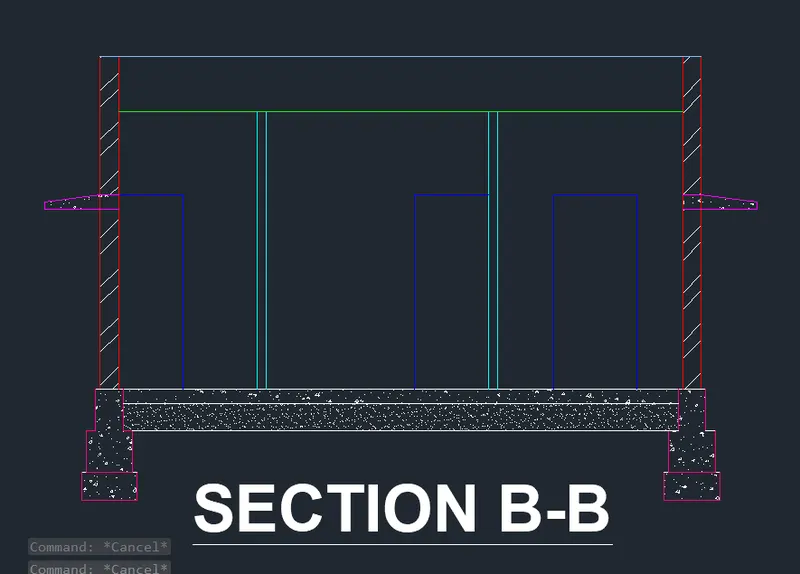
SECTION B-B:
- Project the lines from the elevation for the height and from the section line of plan for the horizontal members.
- Drawing windows, doors and stairs in section.Draw the window and door which we see after cutting the section line.
- Using hatch hatch the walls with the bricks hatch and foundation with the concrete hatch.
- Place the windows and foundations in the respective layers and give colours.
Structural drawings:
1. Column layout:
Step 16:
Placing of columns:
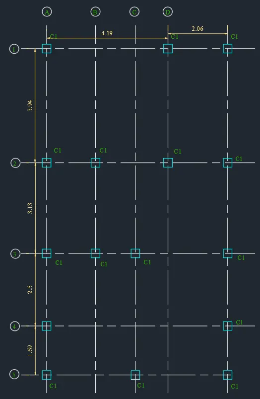
- Column of size 0.25m x0.25m is considered.Columns are placed in all corners of the wall and intersection of walls wherever required.
- Now draw the centre line for column from the annotate tab -centre line.
- Now mark the grid line as 1,2 in the y direction and A, B, C, D, E, F in the x direction.
- Create a circle and insert text into it .
- Dimension between the grid lines is mentioned as it is used for marking the columns.
- Make a layer for Column and place the column in that layer.
Footing Layout:
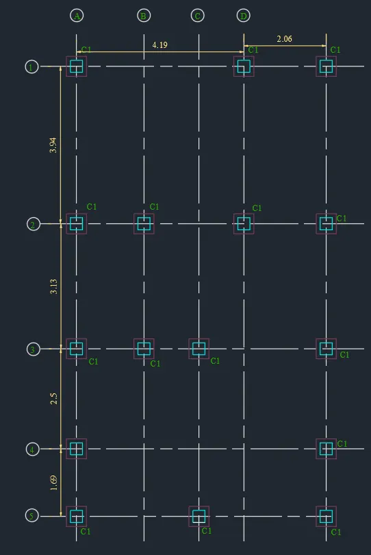
- Isolated footing of size 0.5m x0.5m is provided. Create a rectangle with dimension 0.5x0.5 m, place the centre of rectangle with the centre of column.
- Make a layer for footing and place the footings in that layer.
Plinth beam layout:
Drawing of plinth beam:
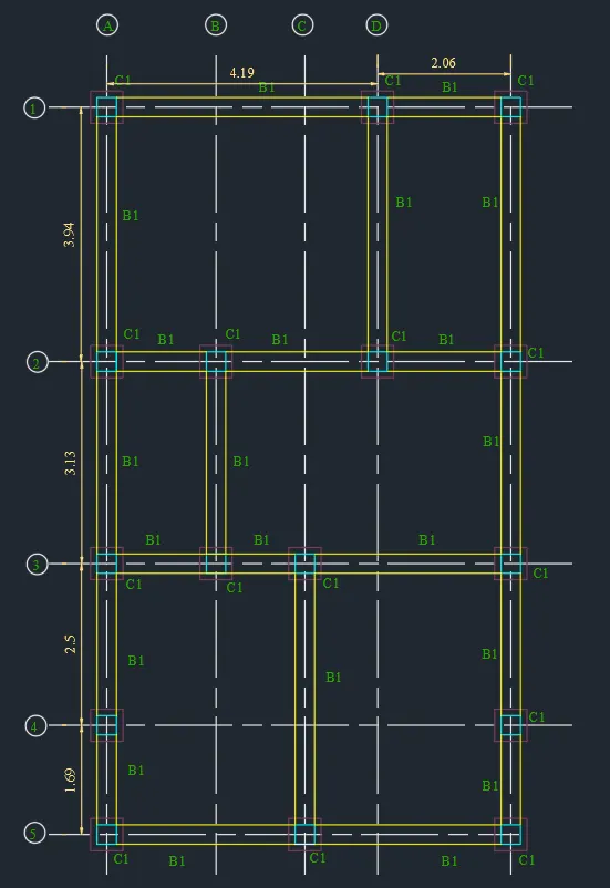
- First connect the columns by beam of width 0.25m, as the wall thickness is 0.25.Plinth beam is provided below all the walls.
- Create a layer for beam and put the plinth beam in that layer.
Result:
Architectural and structural plan of a residential building is drawn in a given Plot size. The Oreintation of the drawing is also referred as Facing East Direction.
1. Architectural plan is drawn
Plot:
Plan:
Elevation:
Section A-A:
Section B-B:
2. Structural plan has been drawn:
Column Layout:
Footing Layout:
Plinth Beam Layout: