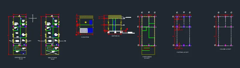
Project 1 _Creating an Architectural plan for the provided plot size and develop relevant basic structural drawings
Challenge 8: Creating the Project on a house having plot size (20’x60’) in which G+1 Floor Plan, Section, Elevation, Plinth beam layout, footing layout and Column layout is drawn with the help of AutoCAD software.
Aim – To draw the Ground floor plan, First floor plan, Section, Elevation, Plinth beam layout, Footing layout and column layout of a plot size 20’x60’
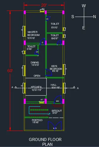
- Ground Floor Plan.
Procedure:
- First create a new Autocad file with imperical units
- Type the command units and set it to Engineering units and set it to inches
- Type the command Dimstyle and in the primary unit set the units to inches and precision to 0.
- Set the limits by using LIMITS command and specify the ends points.
- Give the Xline command and make a horizontal and vertical line
- Trim off the left part of the lines
- From the vertical x line give the offset of 0.8’ in +x direction.
- Again give the offset of 10’ in the same direction.
- Again give the offset of 0.4’ in the same direction.
- Again give the offset of 8’in the same direction.
- Again give the offset of 0.8’ in the same direction.
- Now from the upper horizontal x line give the offset of 0.8’ in – y direction
- Again give the offset of 10’ in the same direction.
- Again give the offset of 0.4’ in the same direction.
- Again give the offset of 5’9” in the same direction.
- Again give the offset of 0.4’ in the same direction.
- Now from the main 0.8’ horizontal line give the offset of 16’ in the same direction
- Trim off the unwanted lines using the trim command.
- Master bed room, toilet 1, toilet 2, is made.
- Now from the last horizontal line give the offset of 6’ in –y direction
- Again give the offset of 0.4’ in the same direction.
- Again give the offset of 16’ in the same direction.
- Again give the offset of 0.4’ in the same direction.
- Now from the main vertical boundary give the offset of 5’ in + x direction
- Again give the offset of 10’ in the same direction.
- Again give the offset of 0.4’ in the same direction.
- Trim off the unwanted lines with the help of trim command
- From the kitchen boundary give the offset of 7’ in –y direction
- Again give the offset of 0.4’ in the same direction.
- Now from the 2nd last horizontal line give the offset of 3.5’ in +y direction
- From this line give the offset of 0.2’ in both +y and –y direction for getting 0.4’ thickness boundary for stairs.
- From the right main vertical boundary give the offset of 8’ in –x direction.
- Trim off the unwanted lines with the help of trim command
- Now make the stairs with the help of line and offset command
- Give the offset of 1’ for each tread
- Make the stairs of Main door with the help of line and offset command.
- Kitchen, Hall, Stairs and Site out is made.
- Again give the offset of 0.4’ in the same direction.
- Extend the line to the main right vertical boundary.
- Draw the doors with the help of Arc option and line command
- Use the “start end direction” option for making curve for door
- D1 and D both are of 6.5’ height and M.D is 7’ in height.
- Draw the windows with the help of line and offset command
- Use the hatch command for giving colours to columns.
- Use the layers properties for assigning different colours and properties to different parts
- Ground floor plan is made.
- First Floor Plan.
Procedure:
- First create a new Autocad file with imperical units
- Type the command units and set it to Engineering units and set it to inches
- Type the command Dimstyle and in the primary unit set the units to inches and precision to 0.
- Set the limits by using LIMITS command and specify the ends points.
- Give the Xline command and make a horizontal and vertical line
- Trim off the left part of the lines
- From the vertical x line give the offset of 0.8’ in +x direction.
- Again give the offset of 10’ in the same direction.
- Again give the offset of 0.4’ in the same direction.
- Again give the offset of 8’in the same direction.
- Again give the offset of 0.8’ in the same direction.
- Now from the upper horizontal x line give the offset of 0.8’ in – y direction
- Again give the offset of 10’ in the same direction.
- Again give the offset of 0.4’ in the same direction.
- Again give the offset of 5’9” in the same direction.
- Again give the offset of 0.4’ in the same direction.
- Now from the main 0.8’ horizontal line give the offset of 16’ in the same direction
- Trim off the unwanted lines using the trim command.
- Master bed room, toilet 1, toilet 2, is made.
- Now from the last horizontal line give the offset of 6’ in –y direction
- Again give the offset of 0.4’ in the same direction.
- Again give the offset of 16’ in the same direction.
- Again give the offset of 0.4’ in the same direction.
- Now from the main vertical boundary give the offset of 5’ in + x direction
- Again give the offset of 10’ in the same direction.
- Again give the offset of 0.4’ in the same direction.
- Trim off the unwanted lines with the help of trim command
- From the kitchen boundary give the offset of 7’ in –y direction
- Again give the offset of 0.4’ in the same direction.
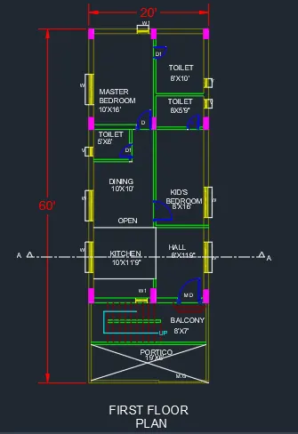
- Do not trim the line as done for ground floor to get the balcony slab
- The whole open space is available after balcony boundary for seeing downward.
- Now from the 2nd last horizontal line give the offset of 3.5’ in +y direction
- From this line give the offset of 0.2’ in both +y and –y direction for getting 0.4’ thickness boundary for stairs.
- From the right main vertical boundary give the offset of 8’ in –x direction.
- Trim off the unwanted lines with the help of trim command
- Now make the stairs with the help of line and offset command
- Give the offset of 1’ for each tread
- Make the stairs of Main door with the help of line and offset command.
- Kitchen, Hall, Stairs and Site out is made.
- Again give the offset of 0.4’ in the same direction.
- Extend the line to the main right vertical boundary.
- Draw the doors with the help of Arc option and line command
- Use the “start end direction” option for making curve for door
- D1 and D both are of 6.5’ height and M.D is 7’ in height.
- Draw the windows with the help of line and offset command
- Use the hatch command for giving colours to columns.
- Use the layers properties for assigning different colours and properties to different parts
- First floor plan is made.
- Elevation
Procedure:
- First create a new Autocad file with imperical units
- Type the command units and set it to Engineering units and set it to inches
- Type the command Dimstyle and in the primary unit set the units to inches and precision to 0.
- Set the limits by using LIMITS command and specify the ends points.
- Type the X line command and select the vertical X line
- Give the vertical projections with the help of X line in vertical directions
- Projections will be taken as vertical line seen in ground floor and first floor plan from the lower horizontal boundary
- Now from the vertical X line made, then at required distance downside give the horizontal X line as lower boundary of elevation
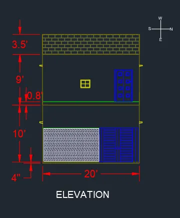
- Give the offset of 4” in +y direction for floor thickness
- Give the offset of 7’ for gate and main boundary vertical wall.
- Then again give the offset of 10’ from floor to get 1st floor slab height
- Give the offset of 0.8’ for slab height
- Give the offset for door and window sill height
- Door height is taken as 6.5’ and window as 3.5’
- From the 1st floor slab boundary give the offset of 9’
- Again give the offset of 3.5’ for parapet wall
- Do the hatching with the help of hatching command
- Make the door with the help of REC command and line command
- Draw the windows lintel with the help of line command keeping ortho off
- Use the layer properties for assigning different colours to different parts
- Elevation is drawn.
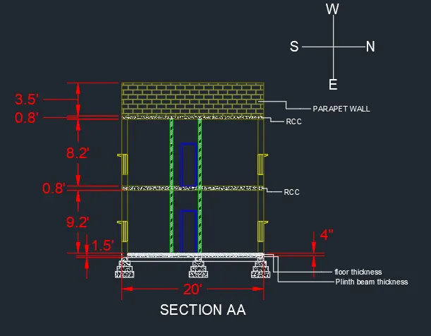
- Section AA
Procedure:
- First create a new Autocad file with imperical units
- Type the command units and set it to Engineering units and set it to inches
- Type the command Dimstyle and in the primary unit set the units to inches and precision to 0.
- Set the limits by using LIMITS command and specify the ends points.
- Type the X line command and select the vertical X line
- From the AA section line see the vertical projections which are visible
- Projections will be taken as vertical line seen after AA sec line in ground and first floor.
- Now from the vertical projections which are made then at required distance downside give the horizontal x line as lower boundary of elevation
- Now from the last horizontal line give the offset of 2.5’ in +y direction for footing height
- Now give the offset of 0.8’ for pedestal in the same direction
- Now give the offset of 1.5’ for the plinth level in the same direction
- Now give the offset of 4” for the floor thickness in the same direction
- Now give the offset of 9.2’ for 1st floor boundary height
- Now give the offset of 0.8’ for first floor slab
- Now give the offset of 8.2’ for the terrace height
- Now give the offset of 0.8’ for slab height
- Now give the offset of 3.5’ for parapet wall
- Draw the door with the help of rectangle command
- Draw the windows with the help of offset and line command
- Type the REC command for making columns and footing
- Type the hatch command and do the required hatching for parapet wall, footing, boundary wall.
- Use the layer properties for assigning different properties and colour to different parts.
- Section AA is drawn.
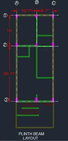
- Plinth Beam Layout
Procedure:
- Take the ground floor plan for making the plinth beam layout
- Erase Windows, Door, Text from the plan
- Only main boundary and walls boundary should be seen
- Now from column to column make the lines from the middle of main boundary and middle of wall boundary.
- Take the line as ISO Dash line for Plinth Beam Layout and giving the distance b/w the grid lines
- Do the dimensioning
- Plinth beam layout is made.
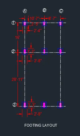
- Footing Layout
Procedure:
- Take the plinth beam layout and erase the main boundary and wall boundary except the ISO Dash line and columns
- From the intersection of the Grid lines make the columns of required length
- Make the columns of length 1.0’ and width 1.75’ at the required positions from the Grid lines.
- Make the footing of required dimensions as F1 (2’4”x2’5”) and F2 (2’8”x3’3”).
- Do the required dimensioning from the centre of grid line
- Mark the vertical Grid Lines as A, B, C and horizontal Grid lines as 1, 2, 3
- Footing layout is made.
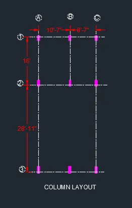
- Column Layout
Procedure:
- From the footing layout erase the footing part which are in rectangle shape, for getting the column layout.
- Do the required Dimensioning.
RESULT: Required information about the plot have been drawn which includes G+1 floor plan, Elevation, Section, Plinth beam layout, footing Layout, column layout.