Project 1 _Creating an Architectural plan for the provided plot size and develop relevant basic structural drawings
Aim: To create the Floor plan, Elevation, Cross Section, Beam layout for the plot size of 60'x20'facing East.
Introduction: Using AutoCAD tool. I have created the whole project using the tools like
- Line command.
- Offset command.
- Mirror command.
- Extend command.
- Fillet command.
- Chamfer command.
- Trim command.
- Xline command.
- Dimension Linear command
- Dimension Contineous command
- Dimension Base command
Procedure: In this Procedure we are going to talk about floor plan, Elevation, Cross Scetion and Beam layouts are made using AutoCAD tool
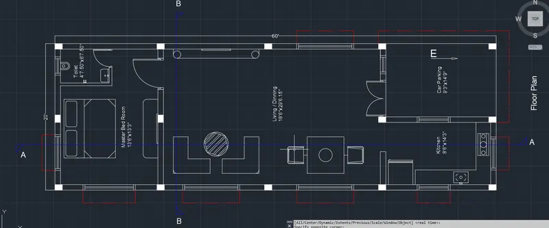
1. Floor Plan:
- Using Line command draw the plot size 60'x20'
- Then offset it inside 9" to create the walls
- According to Vastu Place the main door.
- According to vastu divide the rooms like kitchen, Bed room, living, dining and toilets
- After dividing rooms according to usability provide doors by trimming the lines by Trim command.
- Place bed in bed room according to vastu and space and cuboards
- In Kitchen provide kitchen slab and show gas hub according to vastu.
- After completeing the wall work, mark for column placement with completely invisible in walls and at the same time with safe for builting frame structure.
- Then give line for Cross Sections
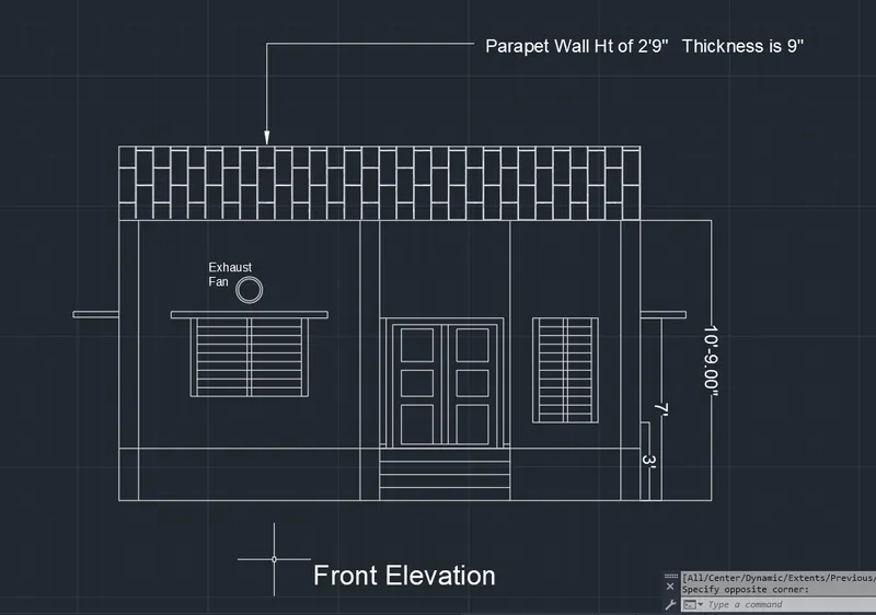
2. Elevation:
- using Xline command take the building outer line and column line and window line and main door line
- Offset the bottom line according to standard like for Basement 3', Lintel 7', Roof level 10'9"and Parapet height 2'9"
- Using offset command trim command draw the window and door to complete the drawing
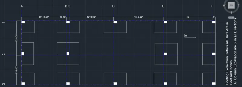
3. Column Pit Layout:
- From floor plan column alone taken and marked according to dimensions
- Mark the excavation dimension around the column
- Column place drawing is most important drawing for marking the site so it should be clear to understand
- After place the column and column pit dimension excavation using dimlinear command mark the dimension and dimcon command mark the dimension correctly then its done.
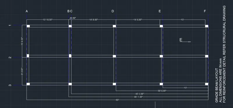
4. Grade Beam Layout:
- From the Floor plan take the column and draw the beam as shown in figure in Grade beam drawing
- According to column arrangement draw the line.
- Draw the Beam size as 9"
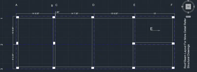
5. Roof Beam Layout:
- According thumb rule D/12 beam depth are Calculated and drawn in drawing
- With the same beam layout drawing the beam are placed according to structural plan
- All beam width is 9" and Beam depth are 12" and 20"
- Dimensions are mentioned correctly
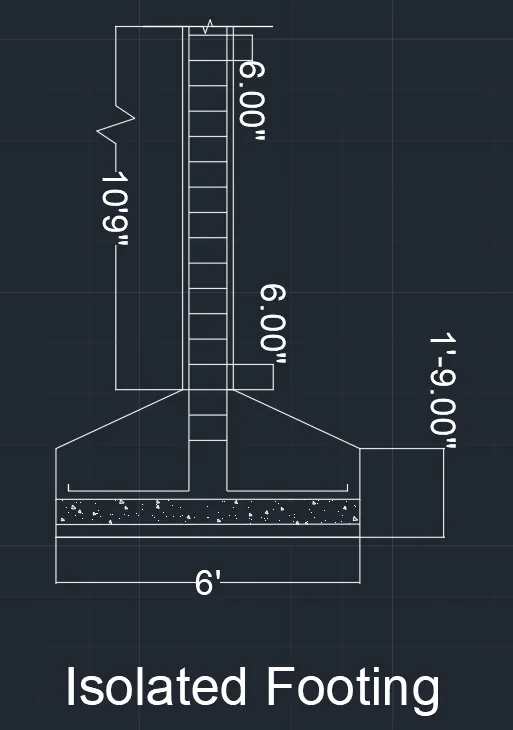
6. Isolated Column Layout:
- According to pit excavation bottom lines are drawn
- The M sand filling level at bottom is mentioned
- The PCC level is marked
- With Cover the bottam mesh is placed and column reinforcement also placed
- Rings are tied with 6" spacing
7.Cross Section Layouts:
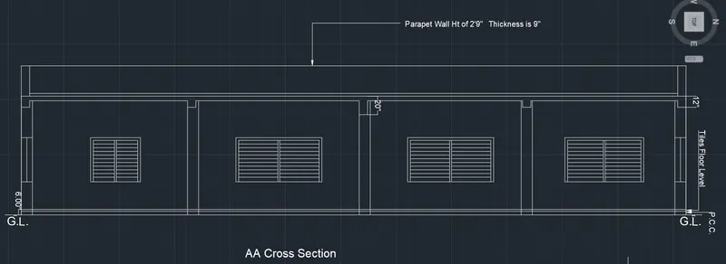
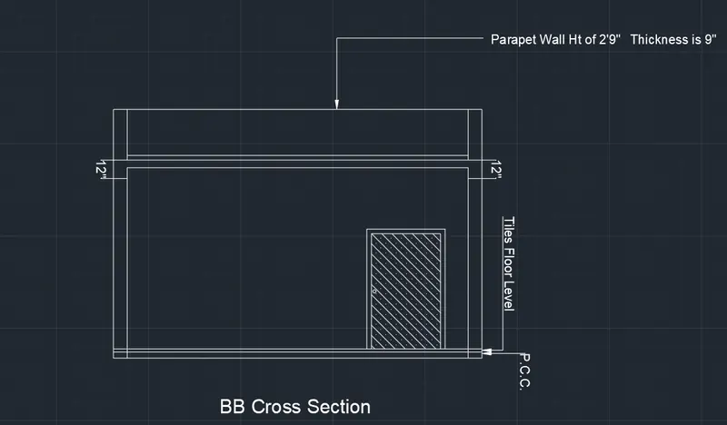
- As shown in floor plan drawing the cross scetions are drawn as AA and BB
- Which shows us the Beams, roof slab and windows
- same as elevation drawing using Xline command mark the column marking, window marking and beams
- Develop from that to exact cross section as shown in drawing.
Conclusion: By doing these procedure i have drawn the drawing in AutoCAD screen shot have attached in it
1. Floor plan:
2.Column Pit Excavation:
3.Grade Beam layout:
4.Roof Beam Layout:
5.Isolated Column Layout:
6.Elevation:
7.AA and BB cross section: