Creating a Floor plan, Footing detail and Isometric view using AutoCad
Aim:
Create a 2d plan and make isometric for that plan with footing details.
Introduction:
Isometric veiw in AutoCAD is like 3D planing drawing method. It will be very useful to understand eveyone.
Procedure:
Open AutoCAD application in advance setting. I have used decimal and milimeter in this AutoCAD drawings.
2D Drawing:
1. Cross Section of Load Bearing Wall on Spread Footing:
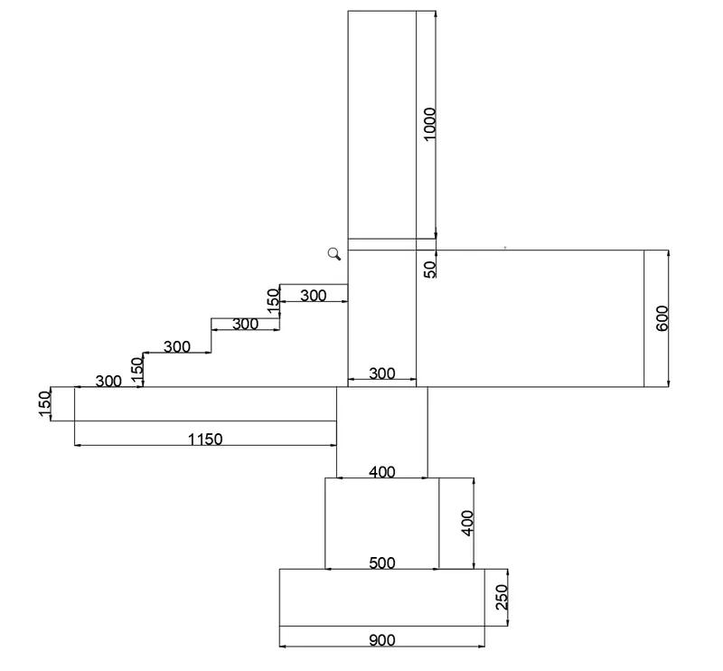
In this Drawing.,I have commonly used only few vommands like,
- Line command.
- Off set command.
- Trim command.
- dimension command.
I have used Relative Polar coordinate and Direct Distance entry coordinate methods.
2. Cross Section of Isolated Footing:
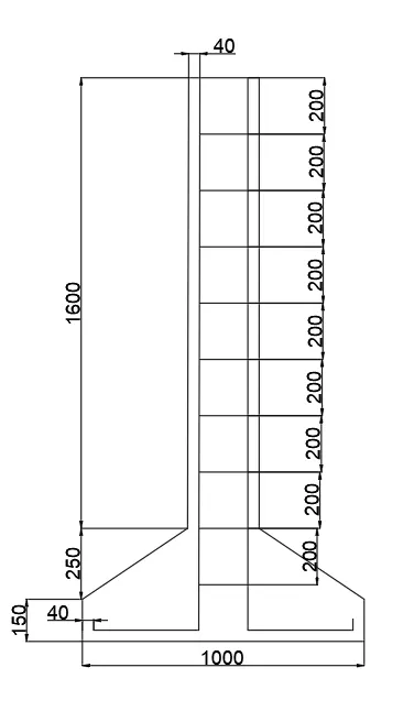
In this Drawing.,I have commonly used only few vommands like,
- Line command.
- Off set command.
- Trim command.
- dimension command.
I have used Relative Polar coordinate and Direct Distance entry coordinate methods.
3. Line Drawing of a Two Room Building:
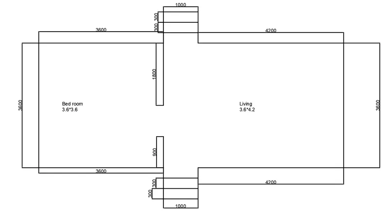
In this Drawing.,I have commonly used only few vommands like,
- Line command.
- Off set command.
- Trim command.
- dimension command.
I have used Relative Polar coordinate and Direct Distance entry coordinate methods.
3. Cross Section of Load Bearing Wall Showing Foundation Detail:
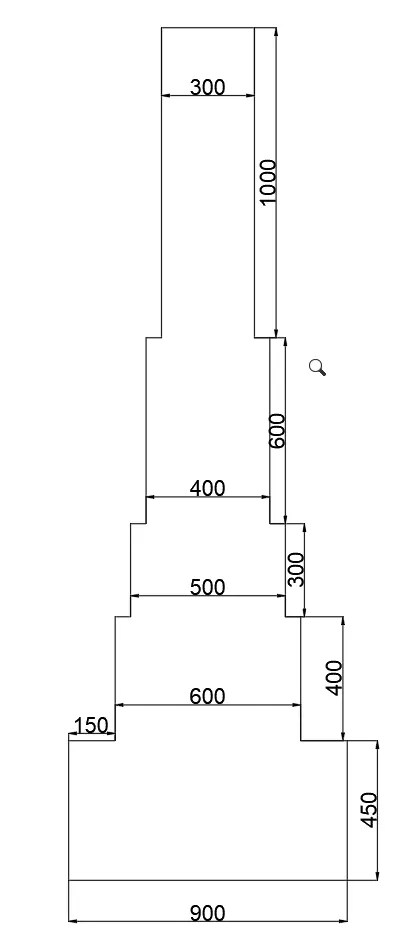
In this Drawing.,I have commonly used only few vommands like,
- Line command.
- Off set command.
- Trim command.
- dimension command.
I have used Relative Polar coordinate and Direct Distance entry coordinate methods.
Isometric Drawing:
1. Isometric View of Steps:
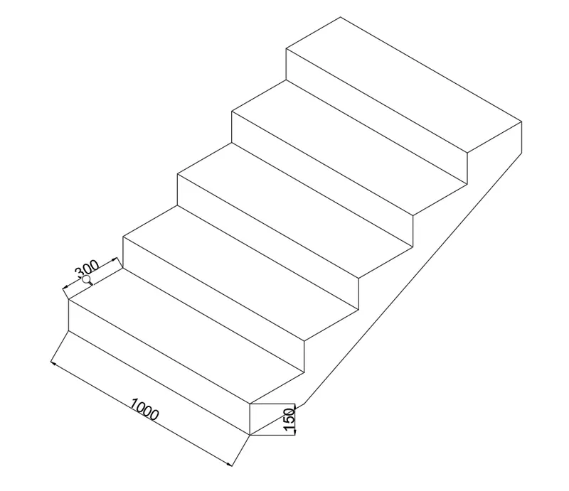
For going to Isometric View using command DSETTING in command line and change Snap type to isometric snap and we will be in isometric view. In Isometric Mode we have to change Top, Left and Right view according to our drawing for that F5 is used as Shoutcut.
In this drawing i have used same command like,
- Line command.
- Copy Command.
- Trim command.
But Only thing in this is we have to change Left, Right and Top frequently. In this drawing, I have used Direct Distance Entry menthods.
2. Isometric View of Gable Wall:
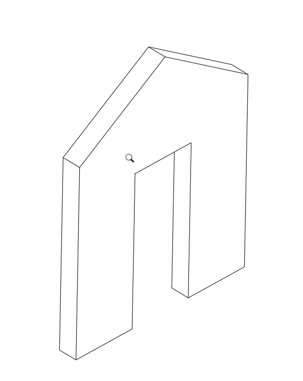
For going to Isometric View using command DSETTING in command line and change Snap type to isometric snap and we will be in isometric view. In Isometric Mode we have to change Top, Left and Right view according to our drawing for that F5 is used as Shoutcut.
In this drawing i have used same command like,
- Line command.
- Copy Command.
- Trim command.
But Only thing in this is we have to change Left, Right and Top frequently. In this drawing, I have used Direct Distance Entry menthods.
Conclusion:
We have created both 2D and Isometric view in AutoCAD.