Project 1 _Creating an Architectural plan for the provided plot size and develop relevant basic structural drawings
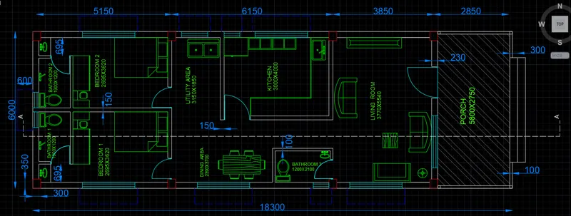
AIM= To design and draft a layout of a residential building for plot size 18.3x6m
PROCEDURE=
PLAN
1. Start with changing the unit to decimal and mm
2. Set the dimensional style manager
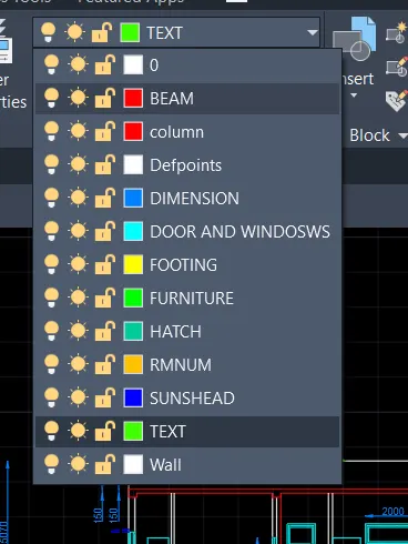
3. Creating the appropriate layer for drafting
4. Now start with the Architecture plan by drawing the plan elevation and section
5. first start with the plan itself
6. First mark the plot corner point and then connect them with the line command
7. Then start with orientating the column for the structure ( column size = 300x350mm)
8. Then with the help of the offset command create an external wall of 230mm thickness
9. Then with the help of line and offset command start creating an internal partition wall of thickness of 150 for the Hall, bedrooms, and kitchen whereas 100mm thick for the bathrooms
10. After creating the wall do the necessary adjustment for the respected room
11. With the help of the ADC command we can use predetermine blocks for the plan for example doors, windows, chairs, bed, sofa, and many more.
12. with the help of the dim linear command determine the dimension
ELEVATION
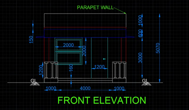
13. Take the elevation of the front part of the building
14. Starting from the ground level. determine the height of the building which would be 5070mm in height
15. At that height of the parapet wall would be 1000mm, and tread= 160mm and 3600mm will be the remaining height of the structure
16. And also determine the door and window for the porch
SECTION A-A
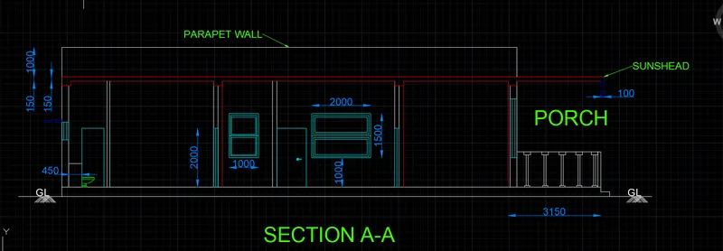
17. First take a copy of the plan and rotate it at 90 degree
18. Now first draw a line for ground level and take the projection for a column for the plan
19. Fix the position of the column at the ground level
20. And then take the side projection for a similar height.
21. Take the height of the slab from sections Elevation
22. Now draw the section by draping the wall, windows, and doors projection from the plan
23. Determine the height from sections A-A
24. Now draw the parapet wall for the height of 1000mm
25. determine the dimension of the structure with the help of the dimension command
26. And with the help of the leader determine the component name and its details
STRUCTURAL DRAWING
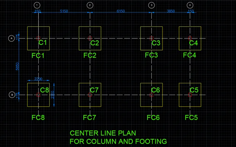
FOOTING AND COLUMN LAYOUT
27. Copy the column with the copy command with the same distance
28. Draw the footing size with the help of the rectangle command for size 2200x2350mm
29. determine the grid line and center-to-center distance for the column and footing
30. With the help of the block and attribute command determine the illustration of the grid
- And also determine the name for each column and footing as shown in figure
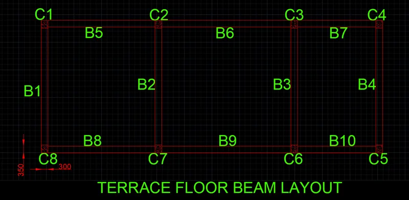
TERRACES LEVEL BEAM LAYOUT
- Copy the column with the copy command with the same distance
- With the help of the line command draw the beam layout for the terrace level
- the size of the beam is 300x350mm
- with the help of text command determine the illustration
- with the help of the dimension command determine the dimension of the beam
RESULT