Project 1 _Creating an Architectural plan for the provided plot size and develop relevant basic structural drawings
QUESTION: Design and Draft a layout of a residential building with the following details:
a. Plot Size: 60’x20’(18.3m x6m)
b. Orientation- Facing East
c. Develop the following: 1. Architectural Drawing (Floor Plan, Elevations, and Sections) 2. Structural Drawing (Column, Bean, Footing Plan)
ANSWER:
AIM:- Aim of this Project is to design and Drafting a Layout of a residential building with the Plot Size is 60'x20' (18.3m x8m) and orientation of this Project is Facing East . After this also developed the folowing object.
1. Achitectural Drawing:
- Floor plan
- Elevation
- Section
2. Structural Drawing:
- Column
- Beam
- Footing Plan
INTRODUCTION:-
- Designing & Drafting: Design is the Starting point of a project plans , and it gives a representation of what the finished project should look like. Design can be a basic outline of the Project or Provide more dtails about its elements .Drafting is where a Project designers become more technical and specific.
- Architectural Drawing: An Architectural drawing or architect's drawing is a technical drawing of a building falls within the defination of architecture. an architectural drawing is a sketch , Plan , diagram , or schematic that communicates detailed. information about a building. Arcgitect and designers creat these types of technical drawings during the Planning stages of a construction project.
- Structural Drawing: A Structural Drawing contains details describing how a structure should be built . During the Project implementation phase , these details must be followed other terms that describes structural drawing are blueprint , construction plans structure plans.
In This Project we have to design the Architectural and structural Plan and Also Provide the section , and Elevation Part of the Architectural Plan.
Required to be provided to the site for construction.
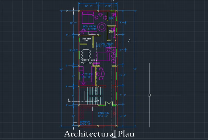
Size in the Plane For Ground Floor area (20'X60'= 1200 Squ. fit)
| S. NO. | Name | Size (in feet and inches) |
| 01 | Living Room | 11'-6" X 15'-3" |
| 02 | Toilet-1 and 2 | 4'X7' |
| 03 | Bed Room -1 | 14'1.5" X 12' |
| 05 | Kitchen | 8' X10' |
| 06 | Dining Room | 7'X11'-3" |
| 07 | Store Room | 7'X 4' |
| 08 | Parking | 10'x12' |
| 09 | Gardenning | 6'-6" x12' |
- in this plan All dimension in feet and inches :
IN THIS DRAWING
- All Columns Provide ( 9" x 9")
- beam size (9" X 9")
- Slab THickness is given 4"
- Internal wall thickness 4.5"
- external wall thickness 9"
- Footing size 4'x4'
EAST FACING VASTU SHASTRA
Opening Provided According to Vastu Shastra
The House is East facing --
- Main door facing - North direction
- Toilet are not placed near the kitchen
- Dining area is bear to the Kitchen far from main door.
- Bedrooms are placed in southwest and east where north east is avoided
- All rooms are rectangle i shape
- Centre house is kept empy.
- Kitchen is placed in south east direction.
- Toilet is in north wesst .
- Livingroom is in north west .
- No overhanging beams are allowed to room
Required Drawing:
- Centre line Drawing.
- Footing and column layout with reinforcement details.
- column schedule with reinforcement details.
- Plinth beam layout with reinforcement details.
- First floor beam layout with reinforcement details.
PROCEDURE:
PROJECT DRAWING LINK
https://web.autocad.com/acad/me/sid/shares/drawings/f659d052-d70d-4c12-a33f-c98993708e66/editor
https://web.autocad.com/acad/me/sid/shares/drawings/f659d052-d70d-4c12-a33f-c98993708e66/editor
1. ARCHITECTURAL DRAWINGS
FOR START THIS DRAWING FIRST OF ALL WE HAVE TO DO SOME SETTINGS ACCORDING THE DRAWING -
SOFTWARE SETTINGS
SETTINGS - OPEN AUTOCAD
- SET DEFAULT SETTINGS - IMPERIAL UNITS [FEAT AND INCHES]
- SELECT A TEMPLATE - ACCORDING TO DRAWINGS
- SELECT A WIZAED - ADVANCED SETUP
- UNITS - ARCHITECTURAL
- ANGLE - DECIMAL DEGREES
- ANGLE MEASURE - ACCORDING TO PLAN
- ANGLE DIRECTION - COUNTER CLOCKWISE
- AREA - ACCORDING TO PLAN
After this enter "D" for dimetion unit and set primary unit DECIMAL set precision 0
MODES -
- GRID ON BY F7 'CONTROL+G'
- USE ORTHO MODE FOR STRAIGHT 90 DEGREE ACCRDING NEED(F8)
- ON POLAR TRACKING (F10) SET ANGLE (15,30,45)
- OBJET SNAP TRACKING (F11)
- OBJECT SNAP (F3)
- TRANPARANCY ON WHEN YOU NEED
SOME OTHER DATA [ASSUMED]
- OUTER WALL THICKNSS - 9"
- INTERNAL WALL THICKNESS 4.5"
- D DOOR - WIDTH [4']
- D2 DOOR - WIDTH [2'6"]
- D3 DOOR - WIDTH [3'-3"]
- HEIGHT OF ALL DOOR [6''8"]
- WINDOW SIZE
W- [4'] - W1- [3']
TO DRAW THE LAYOUT PLAN WE FOLLOW THE FOLLOWING STEPS : -
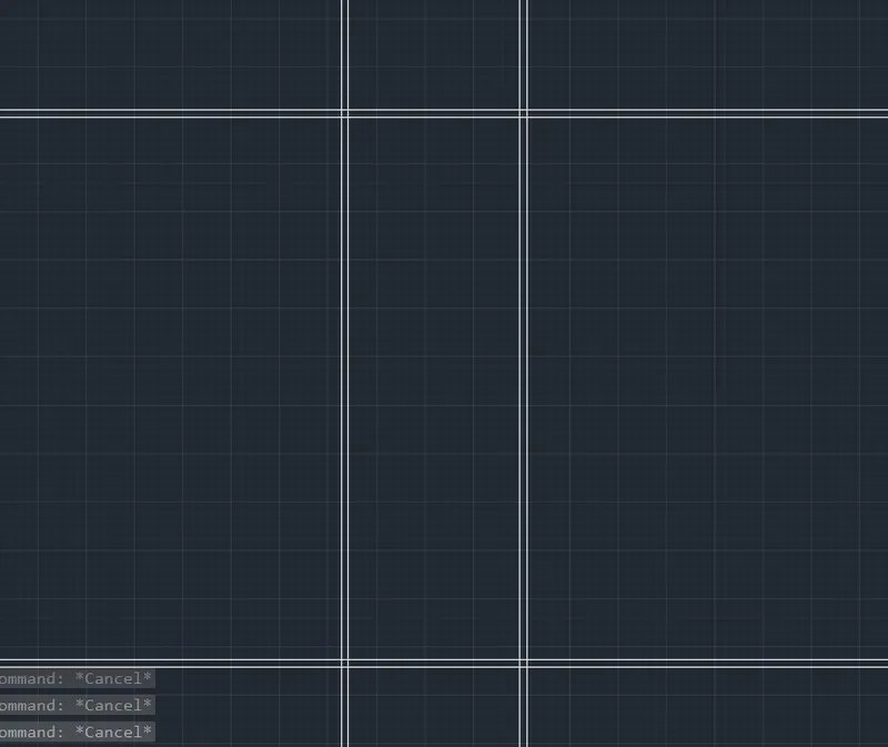
STEP-1
- Take construction line by enter command XL or from ribbon.
- Put it vertically and horizontally according to step one drawings.
- Take offset 9" for give the exterior wall thickness vertically and horizontally
- take 20' offset from vertical XL and take 60' offset from horizontal offset.
STEP-2
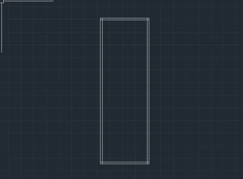
- with the help of trim command erase all the unwanted lines
- Now we have the area of 20'x60'
STEP-3
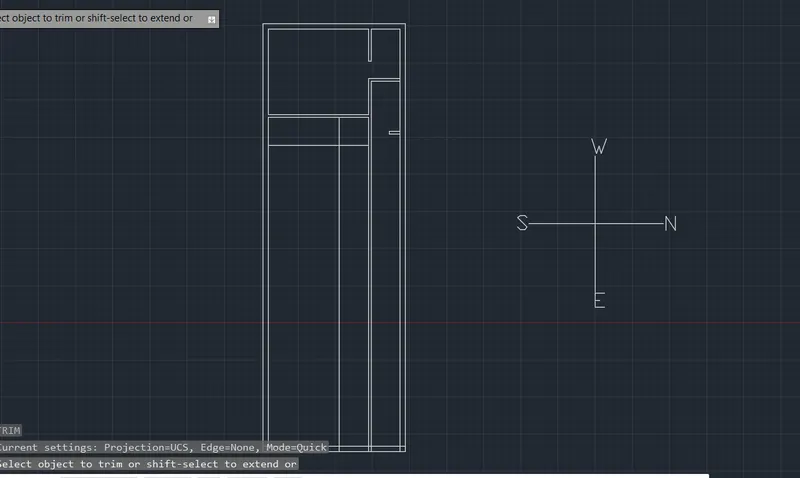
BEDROOM
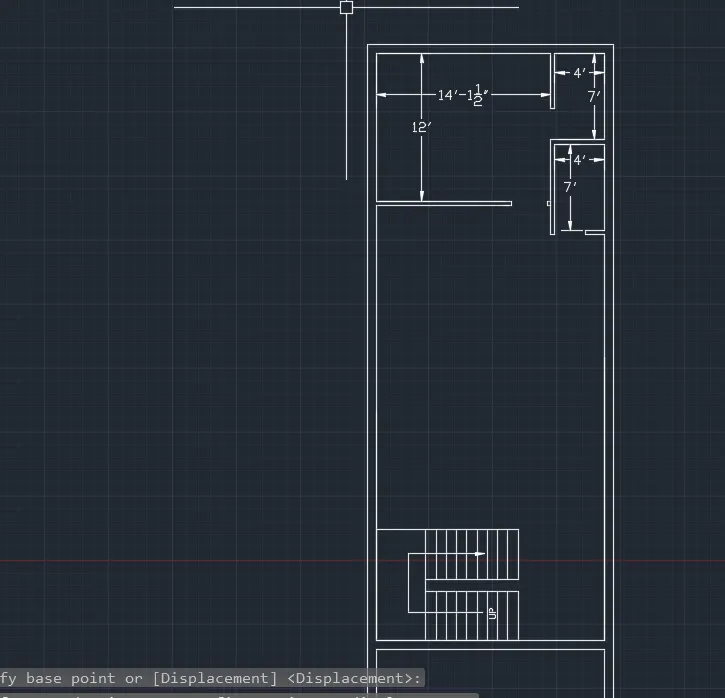
- with the help of line comamnd draw the bedroom of 14'1.5" X12' from the corner of the line for this take offset 14'-1.5" from vertical line and 12' from horizontal line .
- Provide the intarnal wall thickness 4.5" bottom and Right side Of bedroom.
- Draw BEDROOM TOILET 4'X7'. to draw this take offset 4' from upper to downward and offset 7' from vertical line .
- Provide internal wall thiickness 125mm.
STEP-4
TOILET
- For the toilet take offset 4' from vertical right wall to -x direction and take offset 7' from the prevous toilet wall .
- Provide the wall thickness 4.5"
STAIR: (IN THE BLOCK )
- To draw the stair case go to line command dra line and take offset 4' for lenght of the stair and again take offset 4' for stair leave the 1' space betweem them .
- and take offset 6" for riser and 10" for thred.
- Provide wall 9" both side of the stair
STEP-5
KITCHEN :
- For draw the kitchen size of 8'x10'
- take offset from horizontal line of 8' and 10' from stair case wall
- and Provide 4.5" internal wall.
- with the help of trim command erase all the unwanted lines.
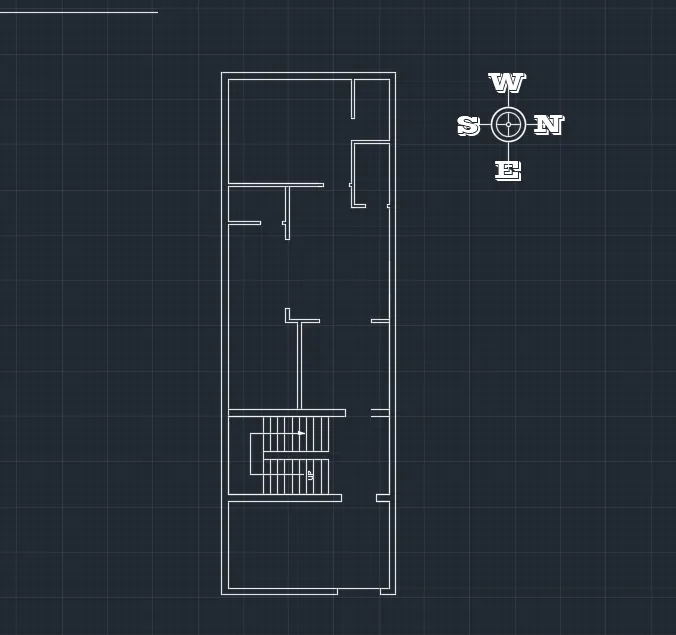
- After that show the direction north ,south ,east west. according dto the plan. and make it a block.
STEP-6
DOORS:
- Now we start putting the door in the wall
- So before putting the doors we have to know the sizes of the door . we assuming the difrent type of door for this plan.
DOOR -D - 4' [ 2'X2'WIDTH]
DOOR - D1- 3' [WIDTH]
DOOR - D2 -2'6" [WIDTH] - Toilet door :- D2 (d1 provide in the tiolet portion )
- Bedroom Door:- D (d door provide in the ENTRANCE )
- FRONT DOOR 5' 2.5'X2.5' Size using line trim and extend command
STEP-7
LAYER PROPERTIES:
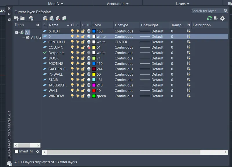
- Now we come to the layere part of the drawing for this go to layer properties
- creat new layer
- Name of the particular layer and set particular line type line weight line color of the layer.
- with the help of new layer make varius layers , wall , column footing , center line , internal wall , chair , table, dimention , stair , window , door gardenning etc.
- and sect particular line type line weight and line color of the object
STEP-8
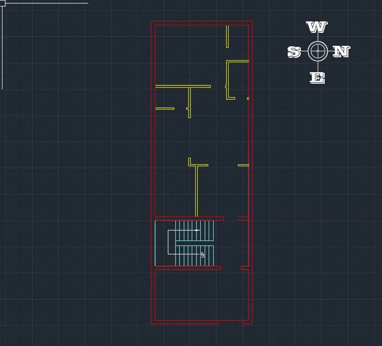
- after making the layer select the objectt and insert into the layer
- Now we can work on the object with particular layer
STEP-9
- Now will start to draw the window and Put it on the outer wall of the building.
- draw manually window of diffrent sizes and Start putting with center point of the line.
- Diffrent window of this Plan Assumed by me is below.
WINDOW - W - [4' WIDTH , HEIGHT 2']
WINDOW - W1 - [2' WIDTH, HEIGHT 2']
WINDOW - W2 - [3' WIDTH, HEIGHT 2']
- This is the diffrent types of window which is required in this plan
STEP-10
COLUMN:
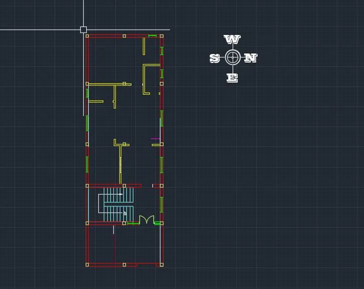
- NOW we start to draw the column and putting it .
- go to column layer and select it cuurent
- take rec command and draw the rectangle of 9"x 9"
- Copy the object and put it to the coner point and column point which is required.
STEP-11
CHAJJA:
- Now we start drawing of chajja of the windows.
- For Chajja of the window go to layer Properties an make new layer 'Chajja'
- Set Line Type- Center line, Line color , And Line weight of the line .
- Than start Drawing to draw the chajjar.
- Take Width of the chajja is 2.5" to 4" and lenght 15"
- and Draw with CHajja layer.
STEP-12
TEST :-
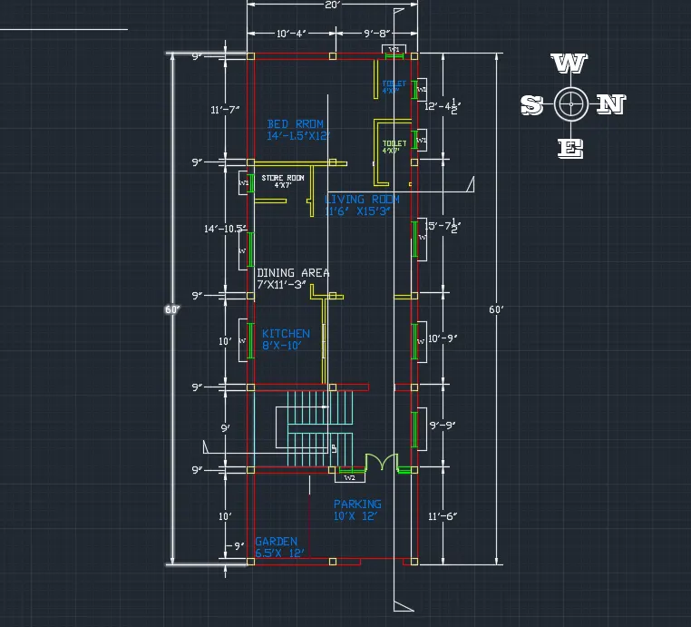
- After this we will text The dimention and name of the object.
- Before this Press 'D' enter set the new dimention style , dimention formate , text style and height of the text.
- After setting the size start the writing part from corner bedroom.
- write Text content and below Size of the room (width X lenght formate
STEP-13
DIMENTION:
- Use Text command to give the plan details with use of Proper dimention style
- Use Center line formate to draw SECTION :-AA' and SECTION BB'
- With the help of trim or erase command trim the all unwanted lines .
- With the Help of Dimention command show all the dimention and after one time dimention take dimcontious for continue the next dimention.
- USE dim-continue for
- give heading of the plan
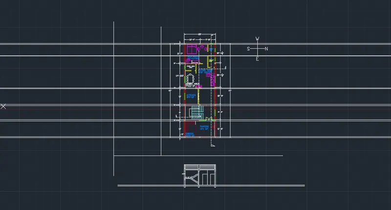
SECTION -AA : AFTER COMPLETED THE PLAN WE WILL START TO DRAWING THE SECTION AA' PART OF THE GIVEN DRAWING.
TO DRAW THE LAYOUT PLAN WE FOLLOW THE FOLLOWING STEPS : -
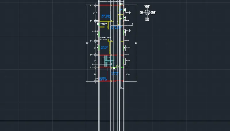
STEP:-1
- Take Construction line and Put it Horizontally below the building plan
- Set the Area according to 3 story of the building.
- Start putting the Pojection of the Plan to the Horizontal line. with the help of Construction line(XL)
STEP-2
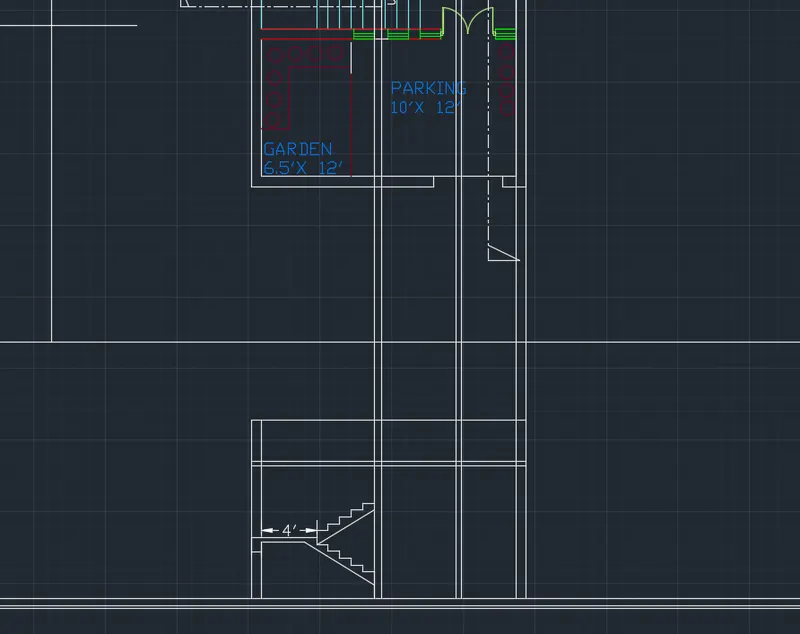
- Now we start making stair of the plan.
- Take stair Projection with help of XL Command.
- For Ground Floor Stair Take 10"Thred and 6" riser
- Start it making with Stair Projection Line.
- Draw stair starting to the landing. and for above stair Select this stair and with use off Mirror Command Mirror it From upward Direction.
- Again Select it and put it above 6" two times.
- Draw the landing With line Coomand distance of 4' from outer wall
- Provide landing thickness 4.5" below
- Take line command and take offset 3' from ground floor point
- again take 4' for lintal lavel
- tan use trim command to trim the lines outside of the window
- use remainning object and start putting remaining projection lines.
- now trim the lines with help of trim command.
STEP-3
- use of projection line draw the door size and
- with the help of line command draw the columns saw in the section part AA
- draw th 3' parapet wall
- Provide slab thickess 4"
- Provide 0.5" water proofing in the roof
- draw the foundation column.
STEP-4
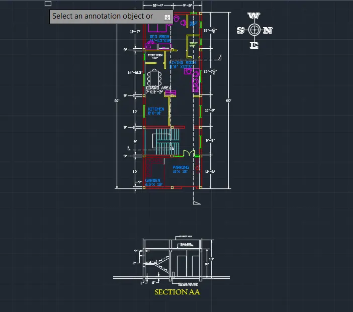
LEADER
- With the use of textt command give section name and with the help of dimention provide the all dimention
- GO to leader command and make new leader with the text height, no of segment point and and scaale
- after that start the writing with the help of leader.
STEP-5
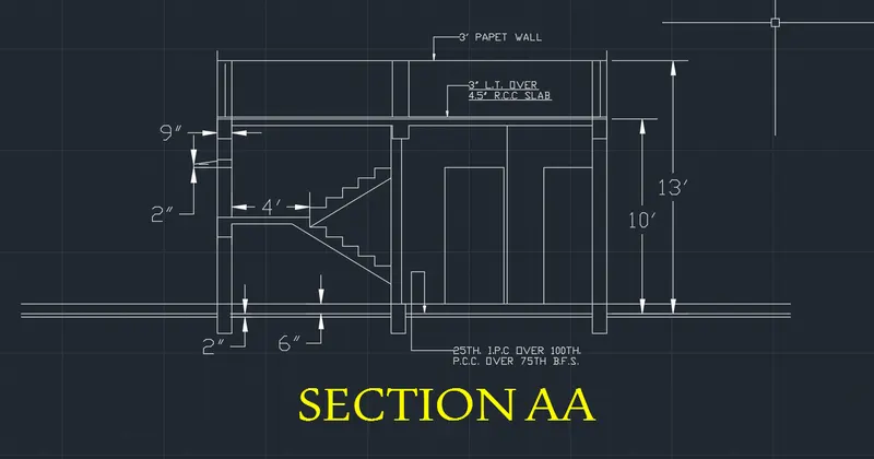
- Use Text command to give the plan details with use of Proper dimention style
- draw SECTION :-AA
- With the help of trim or erase command trim the all unwanted lines .
- With the Help of Dimention command show all the dimention and after one time dimention take dimcontious for continue the next dimention.
- USE dim-continue for
- give heading of the plan
SECTION :BB'
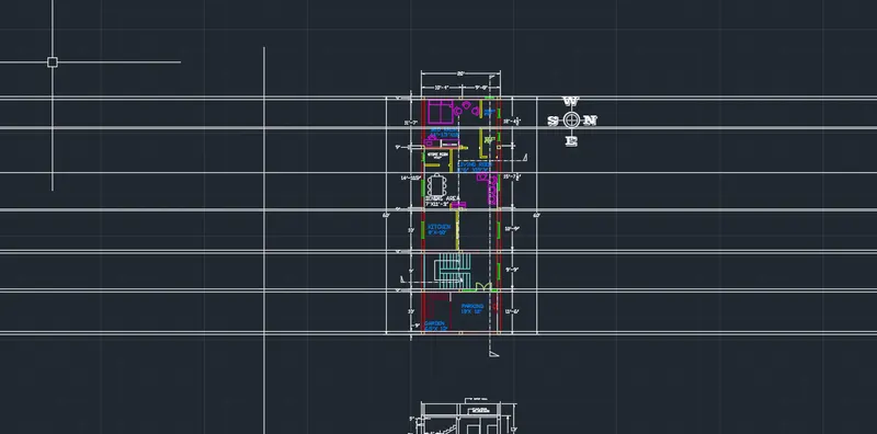
AFTER COMPLETED THE PLAN WE WILL START TO DRAWING THE SECTION BB'' PART OF THE GIVEN DRAWING.
TO DRAW THE SECTION PLAN WE FOLLOW THE FOLLOWING STEPS : -
STEP:-1
- Take Construction line and Put it VERTICALLLY LEFTSIDE OF the building plan .
- Set the Area according to the building.
- Start putting the Pojection of the Plan to the VERTICAL line. with the help of Construction line(XL)
- Firstly putting the outer wall Projection then Window Projection Line.
- Use trim Command And trim unwanted Line And Select Lines For Delete.
STEP-2
- take line command and take offset 3' from ground floor point
- again take 4' for lintal lavel
- tan use trim command to trim the lines outside of the window
- use remainning object and start putting remaining projection lines.
- now trim the lines with help of trim command.
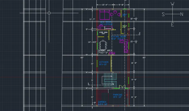
STEP-3
- Start to the the column according to the section part
- and take offset 3; for parapet wall
- draw the section part line flower pot in the parking area.
- Provide slav thickness 4"
- and proofing 1/2"
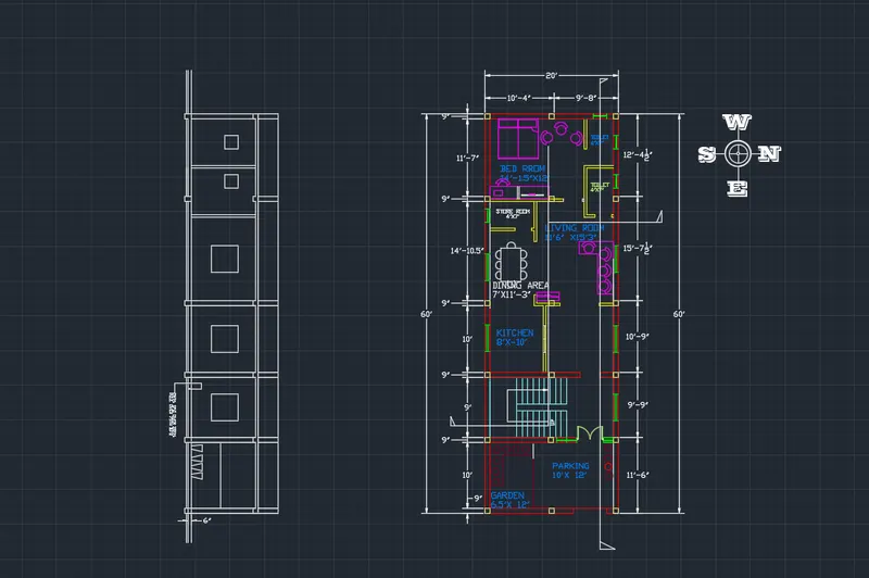
STEP-4
- According To the given Plan Draw the systematically all wall Column and section part
- Go to dimention tool and show the dimention
- For above dimention go to Dim-continue for Continiue the dimention .
- Go to Leader And Use The leader to show the text Content accoring to requiremet.
- before use leader set setting like Arrow size , Text Style, Segemnt POint etc.
- Provide the Drawing name SECTION BB'
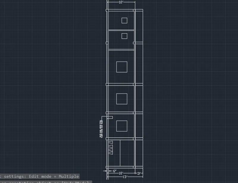
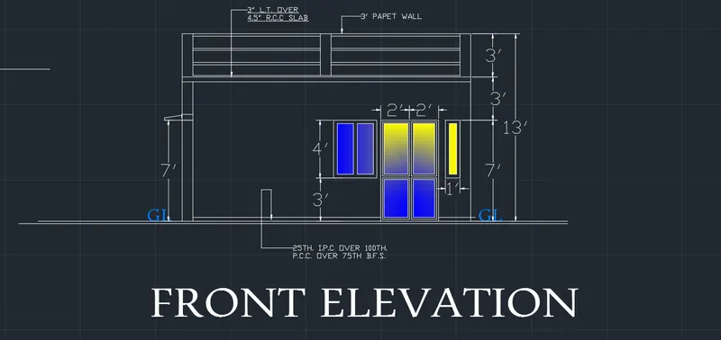
FRONT ELEVATON OF THE DRAWING
STEP:-1
- Take Construction line and Put it Horizontally below the building plan
- Set the Area according to 3 story of the building.
- Start putting the Pojection of the Plan to the Horizontal line. with the help of Construction line(XL)
STEP-2
- Take offset of 3' from horizontal line to draw the window part.
- again take 4' to window lenght
- again take 3'
- and now take 3' for draw the parapet wall
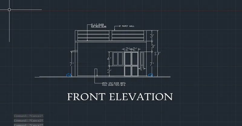
STEP-3
- According To the given Plan Draw the systematically all wall Column and section part
- Go to dimention tool and show the dimention
- For above dimention go to Dim-continue for Continiue the dimention .
- Go to Leader And Use The leader to show the text Content accoring to requiremet.
- before use leader set setting like Arrow size , Text Style, Segemnt POint etc.
- Provide the Drawing name Front Elevation'
- write the ground level .
 \
\
STEP-4
- nowc we use the hatch command to the window and dooe part.
- for hatch command go to hatch command select then and select type of hatching according to you
- and put it where you want.
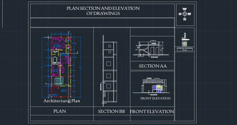
COMBINED DRAWING
2. STRUCTURAL DRAWINGS
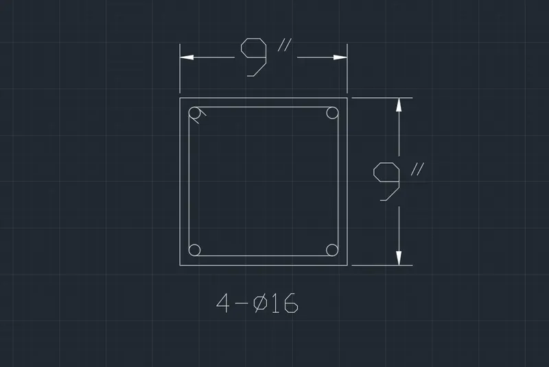
COLUMN
STEP-1
- TO DRAW THE COLUMN GO TO LINE COMMAND
- DRAW LINE OF 9"
STEP-2
- DRAW THE RECTANGLE 9"X 9" WITH THE HELP OF LINE COMMAND
- GO TO THE CIRCLE COMMAND AND DRAW THE CIRCLE .
STEP-3
- USE DIMENTION TO SHOW THE LENGHT OF THE COLUMN
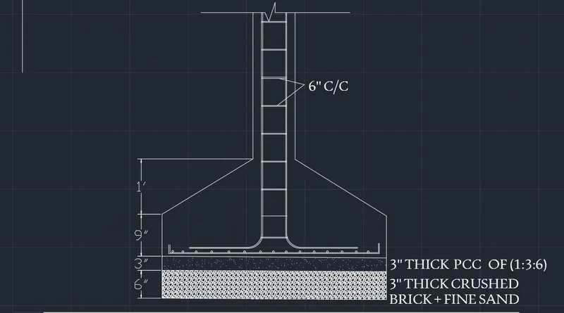
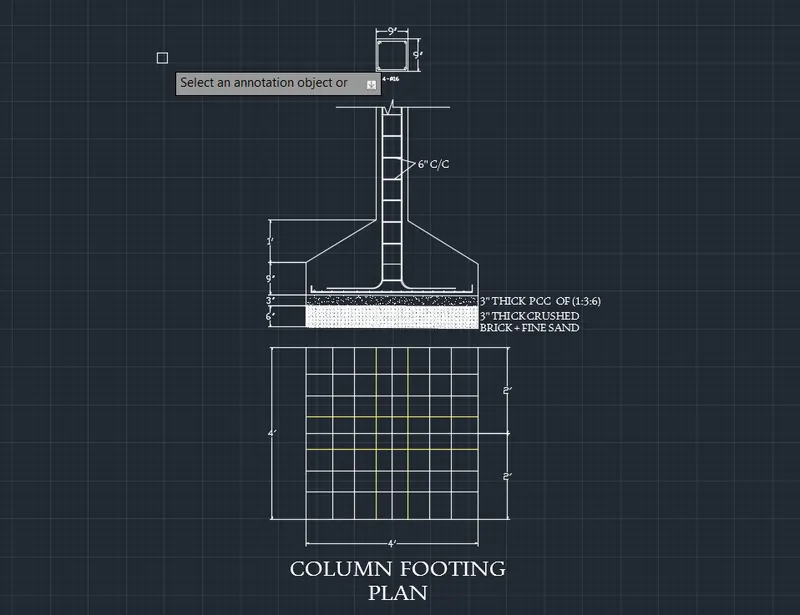
FOOTING DETAILS:
STEP-1
- TO DRAW THE COLUMN FOOTING GO CONSTRUCTION LINE AND PUT IT ON THE COLUMN PLAN CORNER
- PUT IT BOTH SIDE OF THE COLUMN.
- TAKE WALL LENGHT
- AND TAKE OFFSET OF 1' FOR SLOP PORTION OF THE COLUMN
- TAKE 9" OFFSET FOR STEEL
- AGAIN TAKE 3" OFFSET FOR 3" PCC
- TAKE OFFSET OFF 6" FOR THICK CRUSHED BRICK + FINEAND
- GO TO HATCH AND SELECT HATCH FOR SAND AD GRAVEL AND PUT IT IN THE DRAWING PORTION
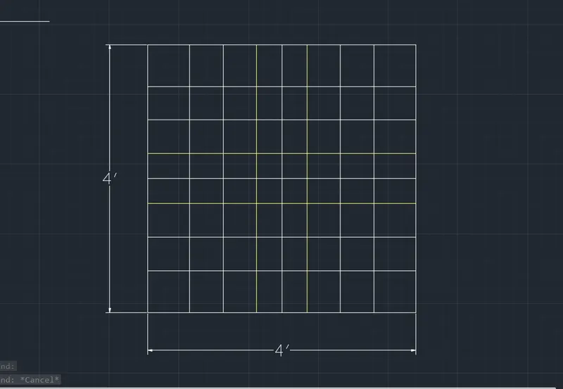
FOOTING PLAN:
- TAKE LINE OF 4' HORIZONTAL AND 4' VERTICAL
- NOW DRAW THE RECTANGLE
- TAKE OFFSET AND PUT DISTANCE 6" X6" CENTER TO CENTER.
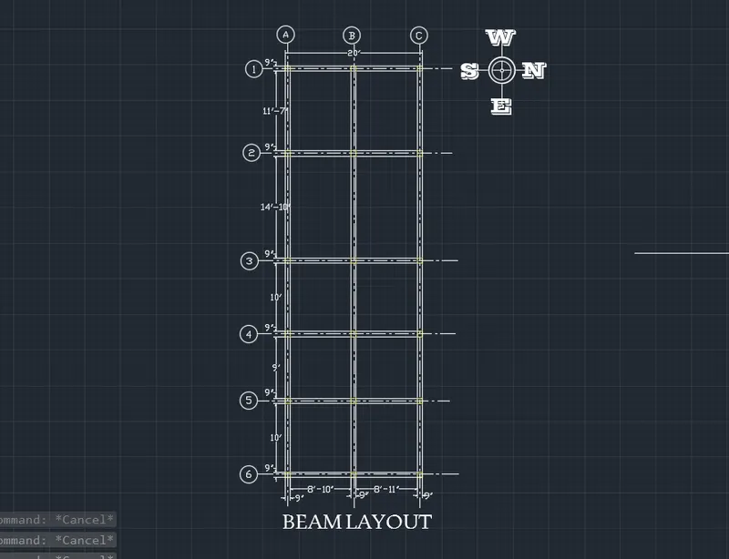
BEAM LAYOUT :
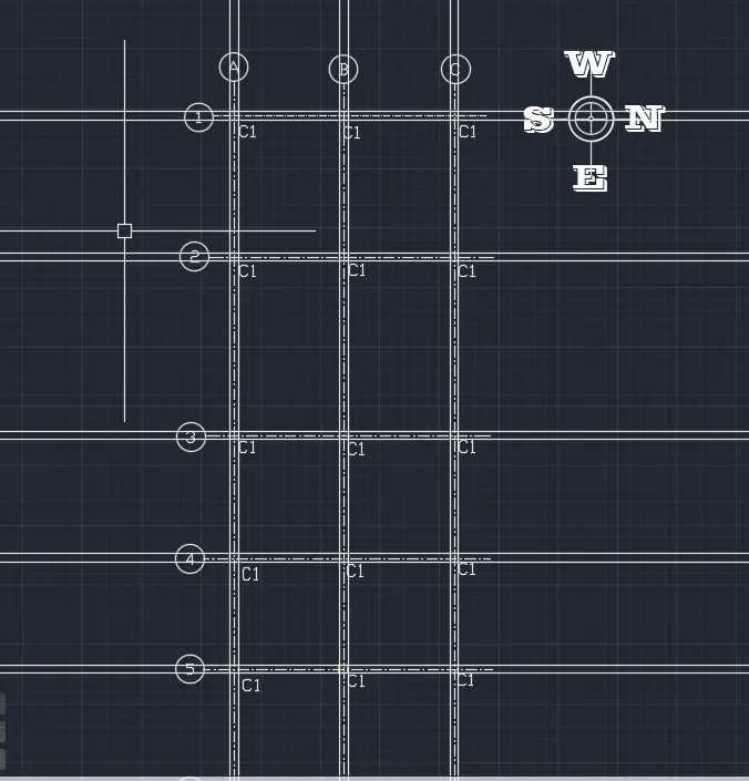
STEP-1
- To draw the BEAM LAYOUT drawing go to layer part
- make a new put 'beam' name of the layer
- with the help of center line drawing put construction out side of the column.
- construction put vertically and horizontally of all columns corner point
STEP-2
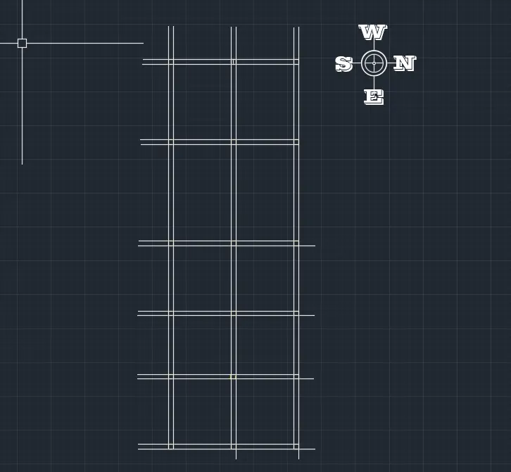
- with the help of trim command trim all the outside unwanted lines or deleted it
- erase all the unnwanted data.
STEP-3
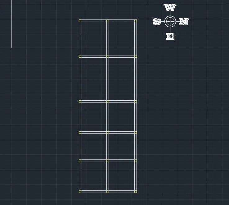
- with the help of rectangle put the column to the all intersect or corner point with the help of copy paste command
STEP-4
- And put it vertically with the alphabets A,B,C
- And put it horizontally with numbers 1,2,3,4,5
- Go to dimention tool and show the dimention floor to floor.
- For above dimention go to Dim-continue for Continiue the dimention .
- Go to Leader And Use The leader to show the text Content accoring to requiremet.
- Before use leader set setting like Arrow size , Text Style, Segemnt POint etc.
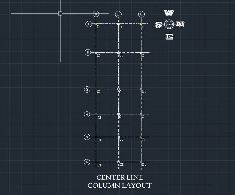
CENTER LINE DRAWING &
COLUMN LAYOUT PLAN
STEP-1
- To draw the center line drawing go to layer part
- make a new layer and set the lyne type center line , line weight and line color.
- set it current
STEP-2
- Go to line command and with the help of previus plan make the center line and erase all the line not center line.
- Put the column name C1
STEP-3
- with the help of leader command make the leader with block
STEP-4
- and put it vertically with the alphabets A,B,C
- and put it horizontally with numbers 1,2,3,4,5
STEP-5
- Go to block option the insert the direction block outside of the drawing.
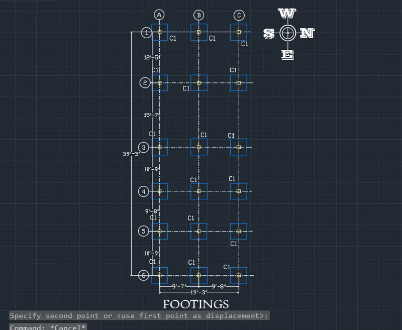
FOOTING PLAN:
STEP-1
- To draw the footing drawing go to layer part
- make a new layer with the name of footings and set the laer type line , line weight and line color.
- set it current
STEP-2
- Put the column name C1 at all the column
STEP-3
- with the help of leader command make the leader with block
STEP-4
- and put it vertically with the alphabets A,B,C
- and put it horizontally with numbers 1,2,3,4,5
STEP-5
- Go to block option the insert the direction block outside of the drawing.
STEP-6
- Put the column and after that put the footing with size of 3'-6" with the center of the column
- putting all the footings with seprate column .
- for the footing take offset 1'-9" both side and with the help of
STEP-7
- Go to dimention tool and show the dimention floor to floor.
- For above dimention go to Dim-continue for Continiue the dimention .
- Go to Leader And Use The leader to show the text Content accoring to requiremet.
- before use leader set setting like Arrow size , Text Style, Segemnt POint etc.
RESULT:
ALL THE GIVEN PLAN, SECTIONS AND ELEVATION DRAWINGS ARE COMPLETED WITH THE PROPER DIMENTION TECHNIQUES DIMENTION STYLE .AFTER MAKING THE DRAWING FINAL DRAWING SCREENSHOTS ARE ATTACHED WITH RESULTENT DRAWING .THE LINK OF THE DRAWING OF AUTOCAD IS ALSO ATTACHED FOR REFRENCE.
PROJECT DRAWING LINK
https://web.autocad.com/acad/me/sid/shares/drawings/f659d052-d70d-4c12-a33f-c98993708e66/editor
https://web.autocad.com/acad/me/sid/shares/drawings/f659d052-d70d-4c12-a33f-c98993708e66/editor
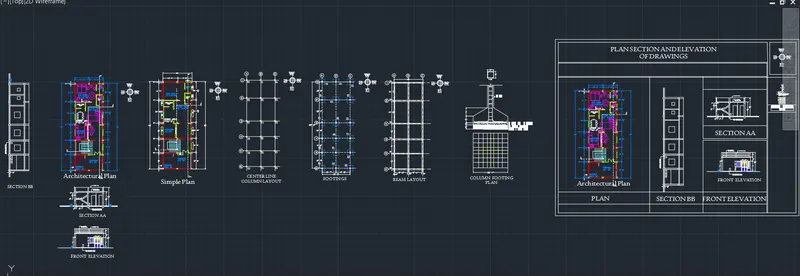
IN THIS PROJECT FOLOWING DRAWINGS ARE ATTACHED :-
- SIMPLE PLAN
- ARCHITECTURAL PLAN
- COLUMN FOOTING DETAILS
- FOOTING PLAN
- CENTER LINE COLUMN LAYOUT
- BEAM LAYOUT
- SECTION AA
- SECTION BB
- FRONT ELVATION
FINAL DRAWING:
DRAWING NO.1
DRAWING NO.2
DRAWING NO.3
DRAWING NO.4
DRAWING NO.5
DRAWING NO.6
DRAWING NO.7
DRAWING NO.8
DRAWING NO.9
ALL DRAWING