Project 1 _Creating an Architectural plan for the provided plot size and develop relevant basic structural drawings
Aim & Introduction: To design and Draft a layout of a residential building in AutoCAD. plot size is taken as 60’x20’(18.3m x6m)/ The facing of the building it taken to East side. Need to draft the architectural and structural drawing. Floor plan, elevation and two sections are drafted as part of Architectural drawing. Column layout, Beam and Footing layout are drawn as part of the Strutural drawing of the building.
Procedure:
a. Architectural Drawing - Floor Plan
1. Open the new file in AutoCAD and using Units commands set the units as Engineering.
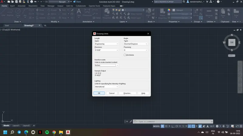
2. Use limmax command and set the limits of the sheet. At present choosen 20'x20'.
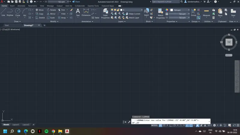
3. Give Zoom command and select All. First drawing the floor plan of the residential building.
4. Draw the horizontal line of 20' and draw a rectangle as shown for the lawn are with 6'3"x9'8" area.
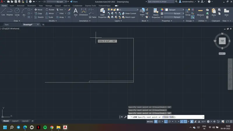
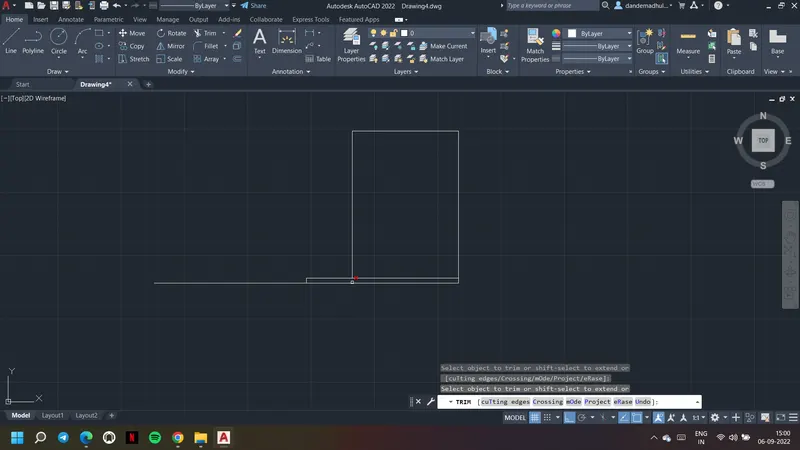
5. Give offset command and give offset distance as 9" as it is the exterior wall.
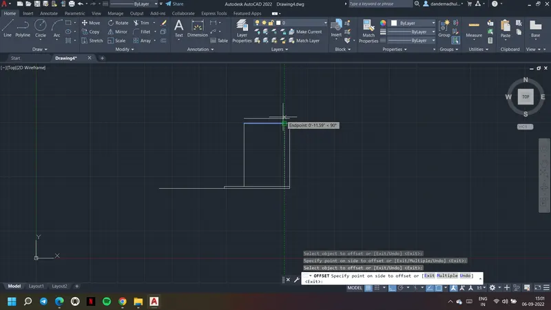
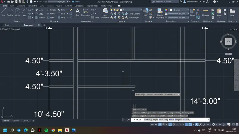
6. Using trim command remove all the extra parts.
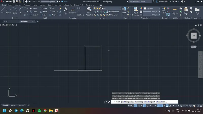
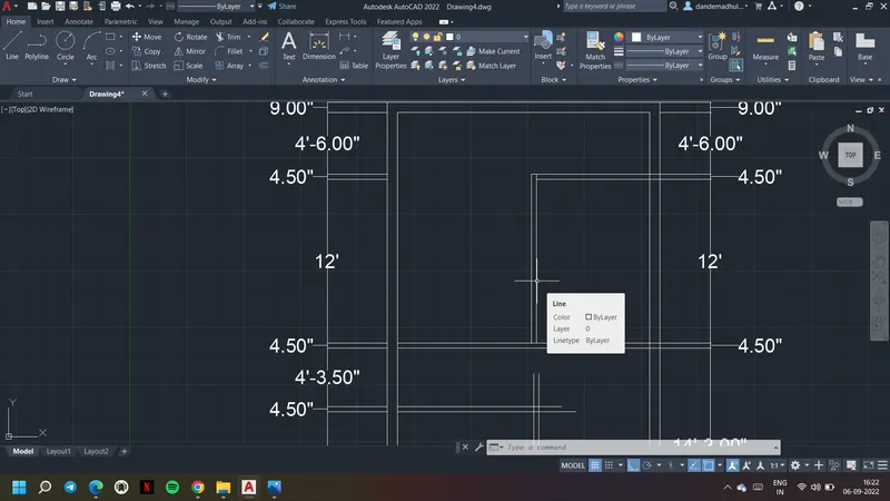
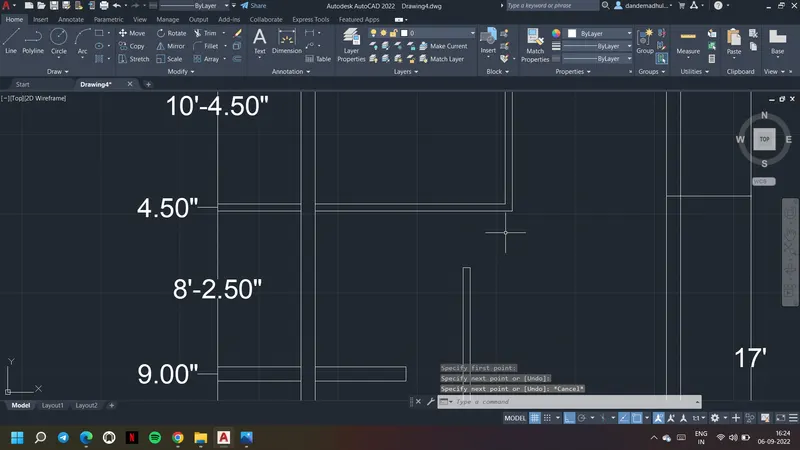
7. Using line comamnd and ortho mode, draw the line in vertical directions according to the room dimensions in vertical direction.
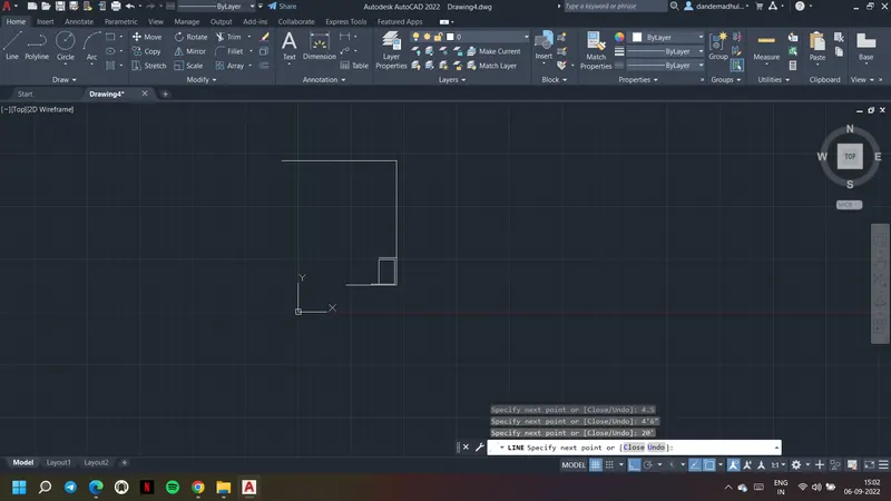
8. Offset the lines with 9" offset distance using offset command.
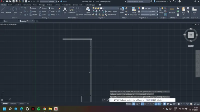
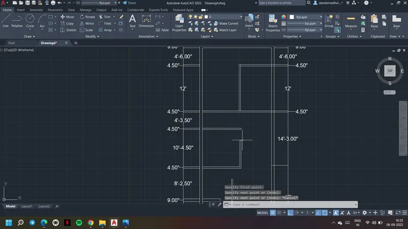
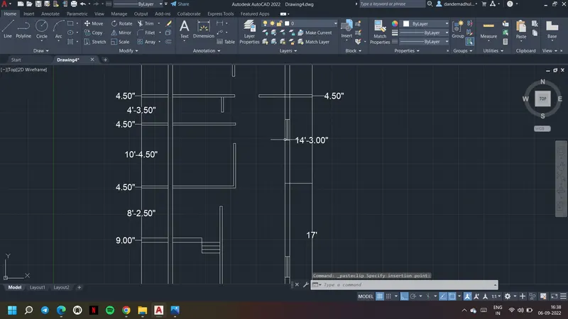
10. Use dimlinear and dimcontinue commands to measure the dimensions as shown.
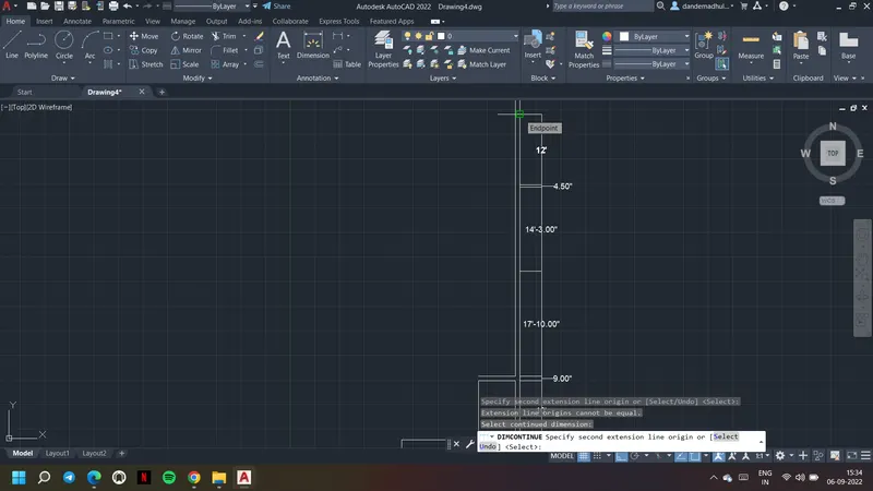
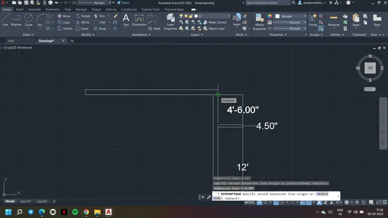
11. Similarly draw the linesthe other side of the building which is 60'.
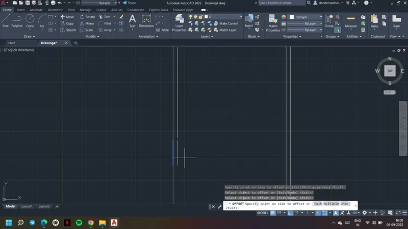
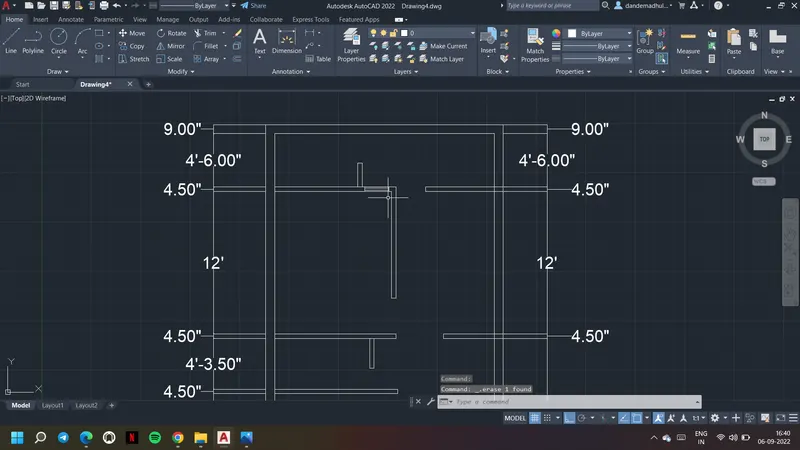
12. Draw the interior walls accrodingly to form the rooms according to the plan
13. Take the interior walls offset distance as 4.5".
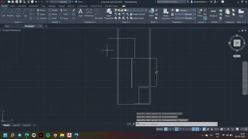
14. Use the trim comamnd to trimt he extra parts wherever required.
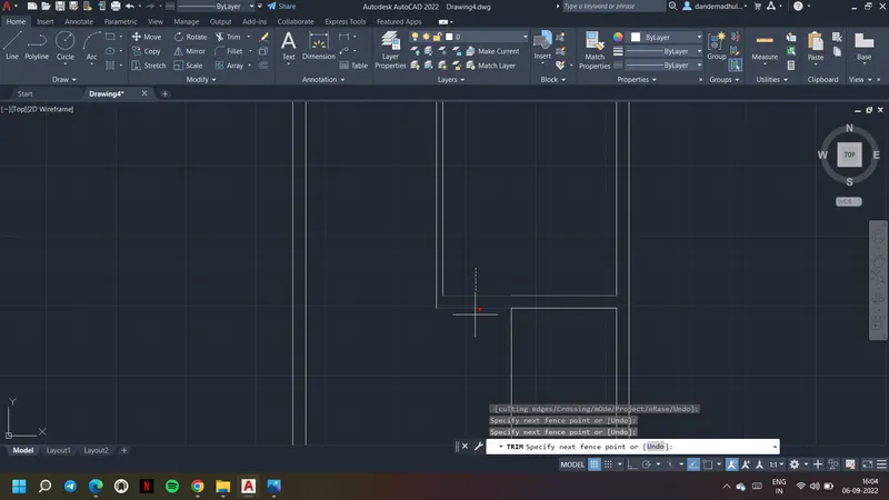
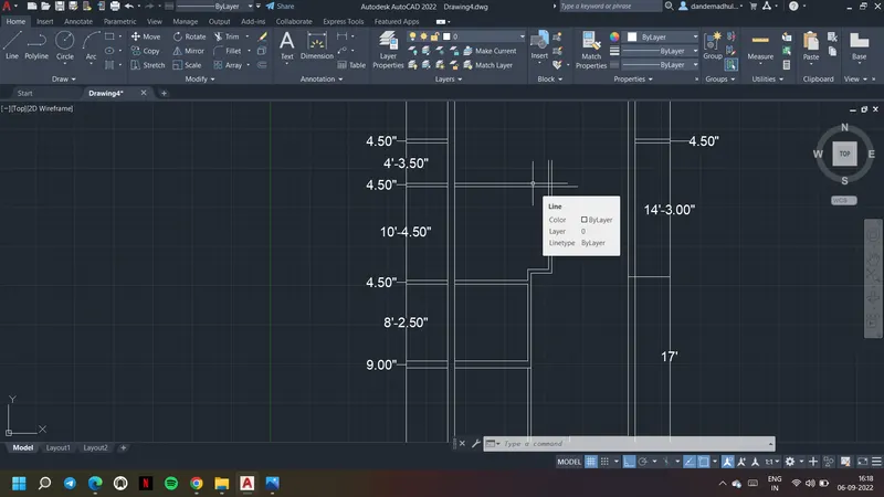
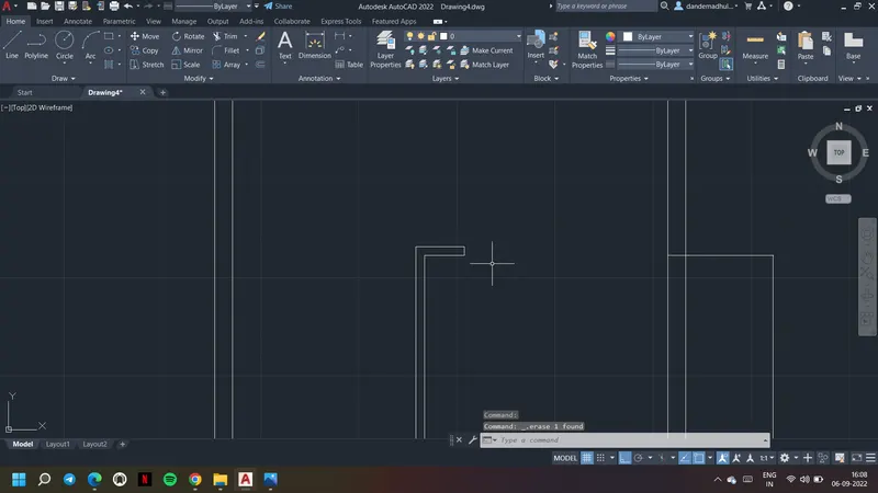
15. Draw all the rooms accordingly using line, offset commands.
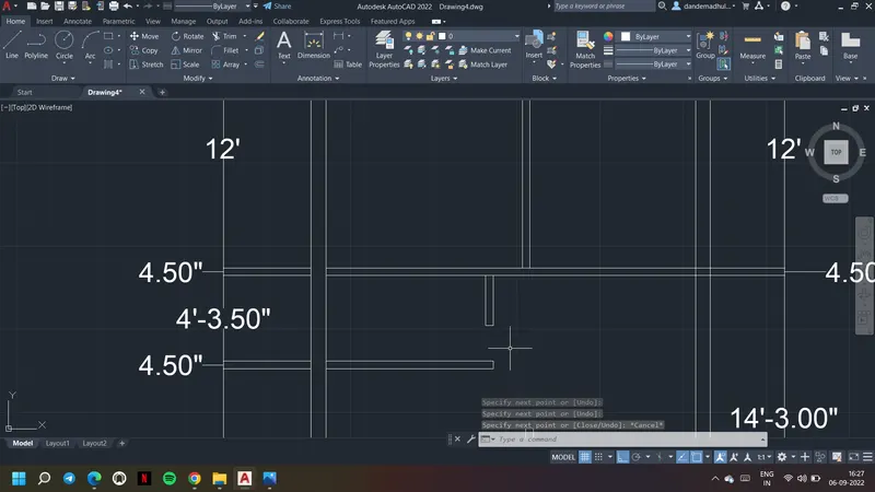
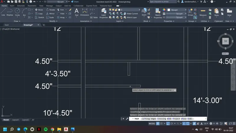
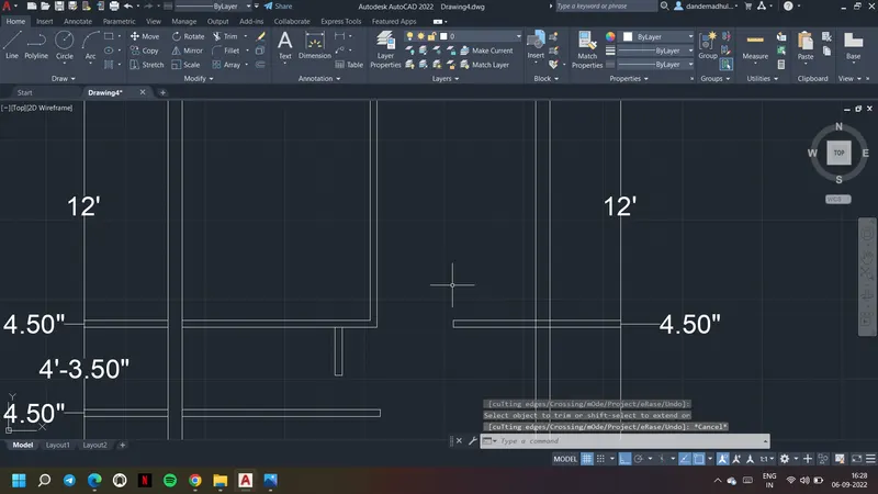
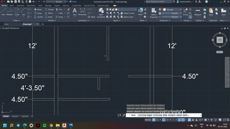
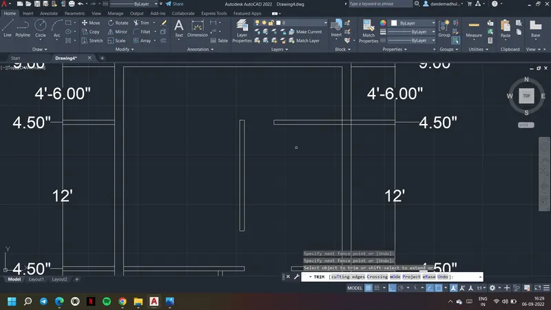
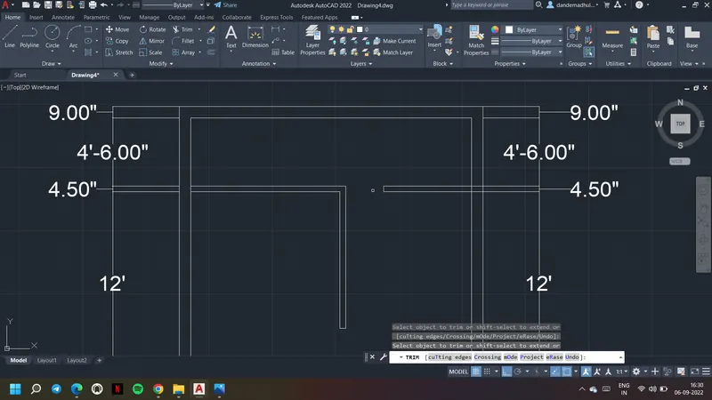
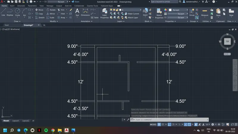
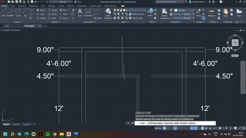
16. At the entra steps are drawn with 10" thread and 7" riser.
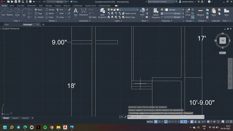
17. For waiting room to steps are drawn with same dimensions.
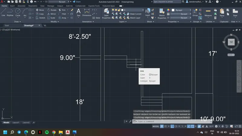
18. Windows and ventilators are drawn respectively whereever required for all the rooms.
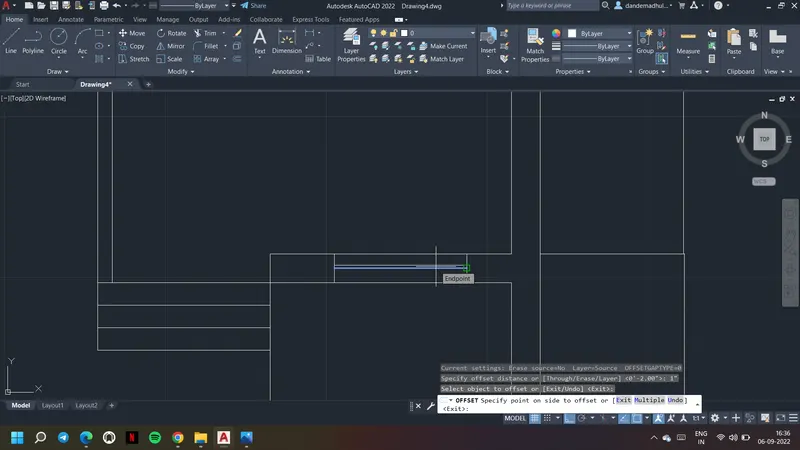
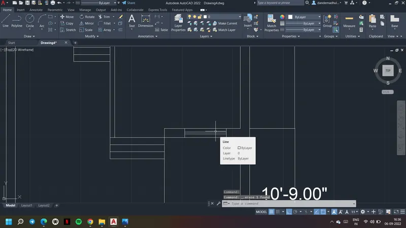
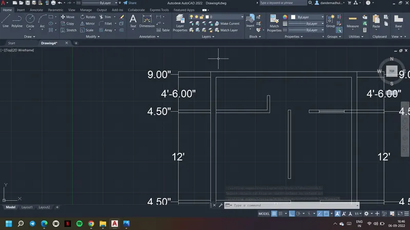
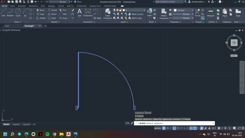
19. To insert the doors blocks are created. At first 3' door is created.
20. Draw a line of length 3' and create to rectangles at it ends to form hinges.
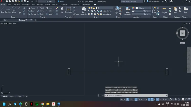
21. Give circle command and draw a circle. Trim the extra part using trim command to form door.
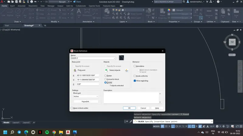
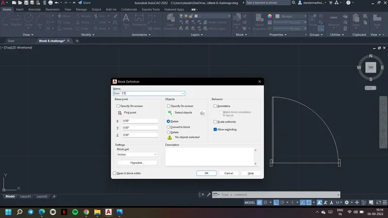
22. Form a block for this door.
23. Insert this 3' door wherever required according to the building plan.
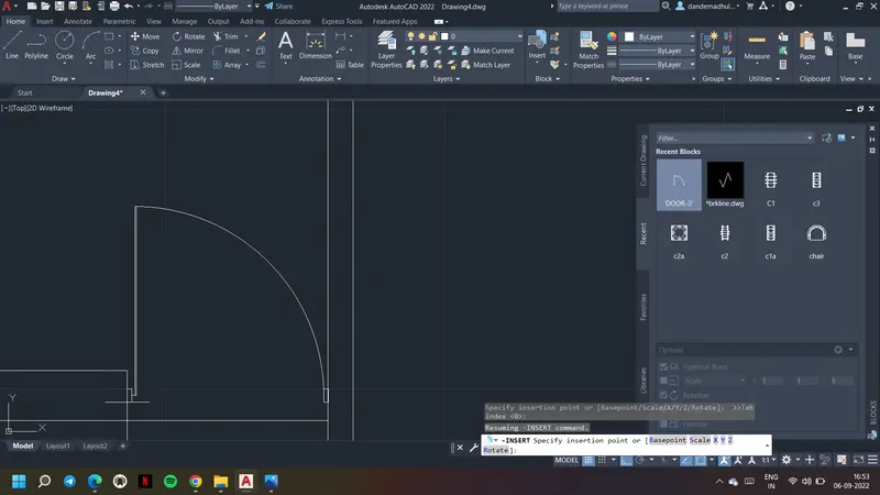
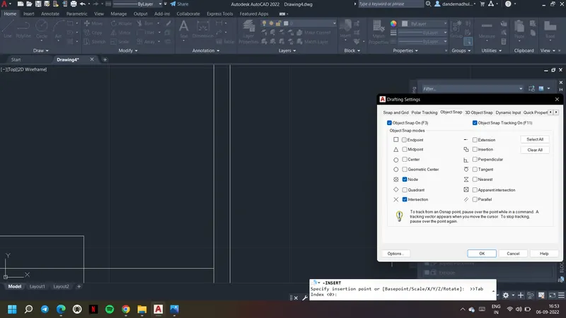
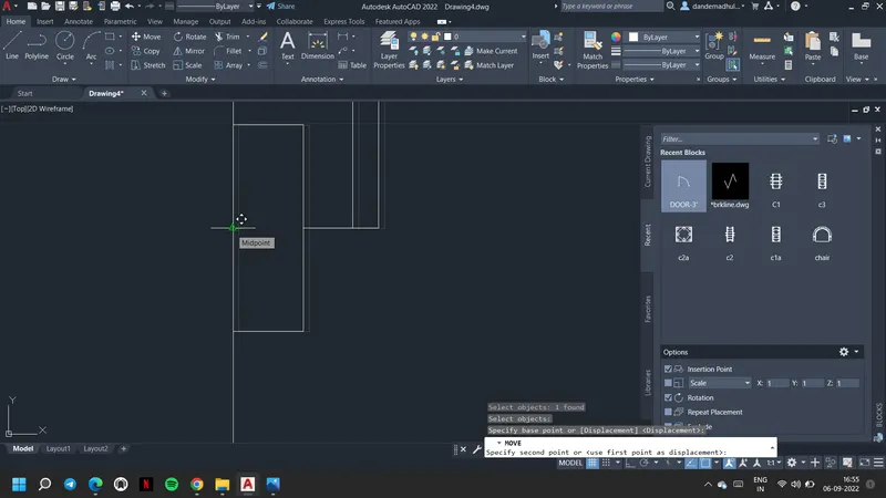
24. Similarly draw 3'3" and 2'6" door and create respective blocks.
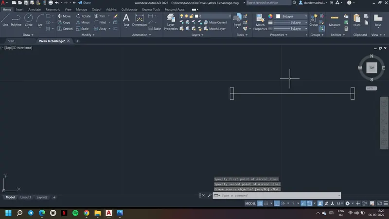
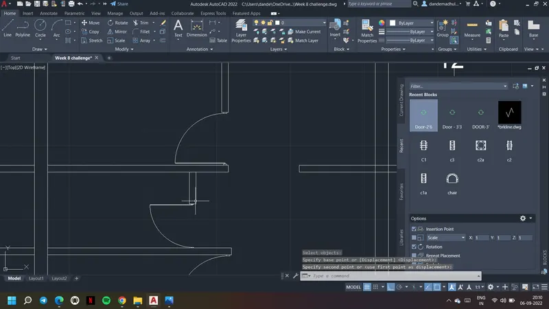
25. Using insert comamnd insert them. Place them accordingly by rotating as required.
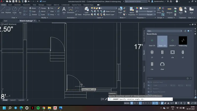
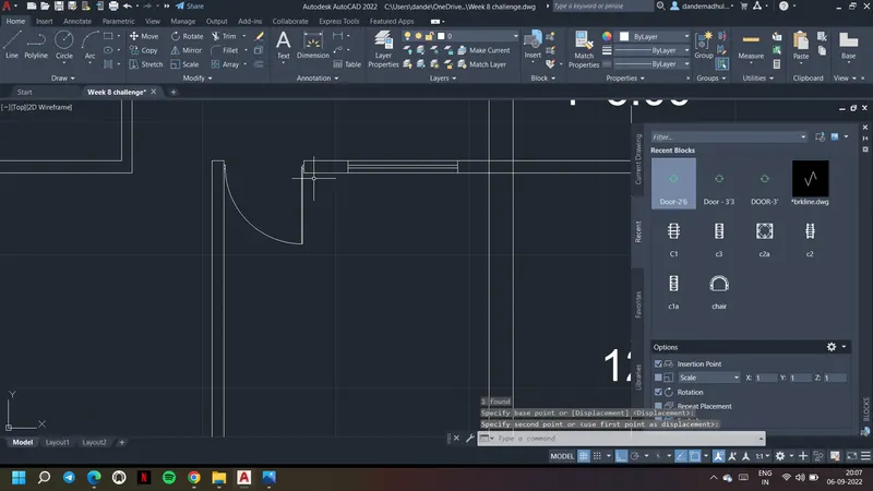
26. Use rotate, mirror comamnds if required to place the doors as required.
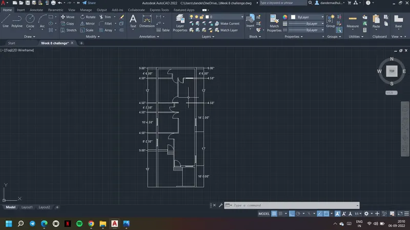
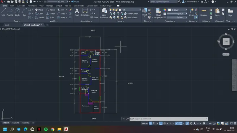
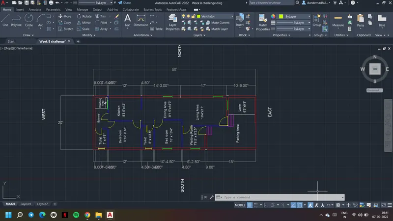
27. Give Text command to insert the text and to name each room according to the plan of the building.
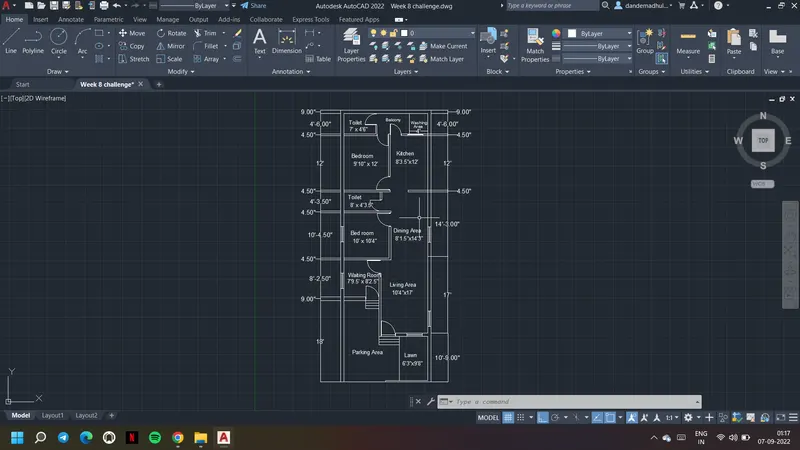
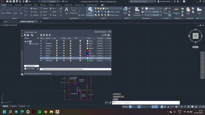
28. Layer command is used and layers are created accordingly.
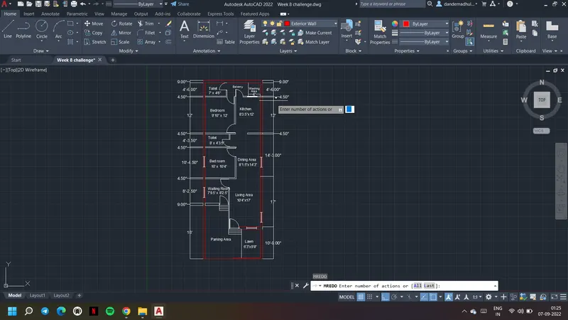
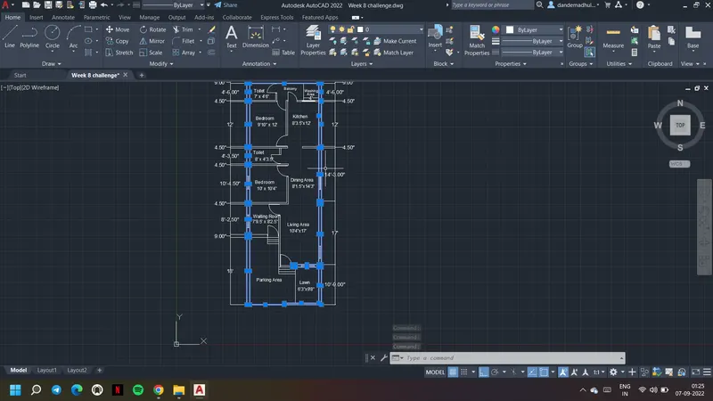
29. The parts are selected and assigned them to a particular layer.
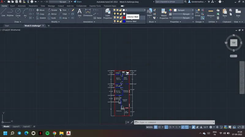
30. Use Matchproperty command and match the properties as required.
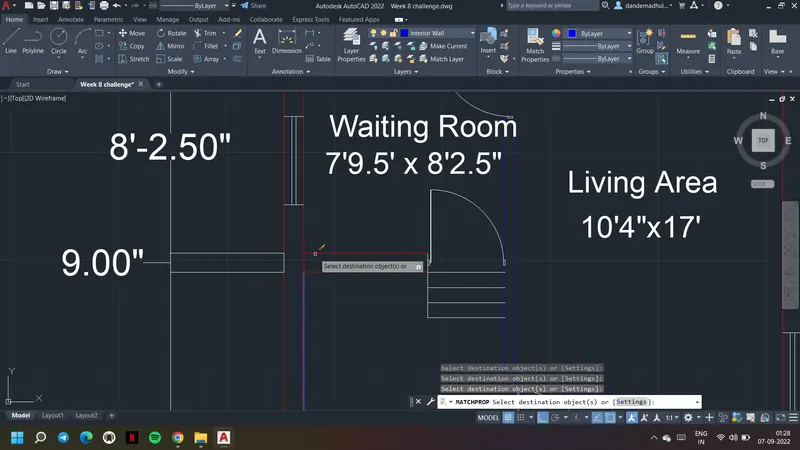
31. Similarly all the layers are created and all the parts are assigned to the respective layers.
Result: a. Architectural Drawing - Floor Plan
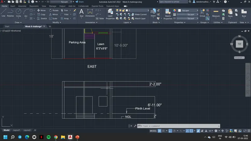
b. Architectural Drawing - Elevation
1. Elevation is drawn using projections of the floor plan.
2. Use xline command and draw horizontal line. Use xline comamnd and draw projections from floor plan as shown
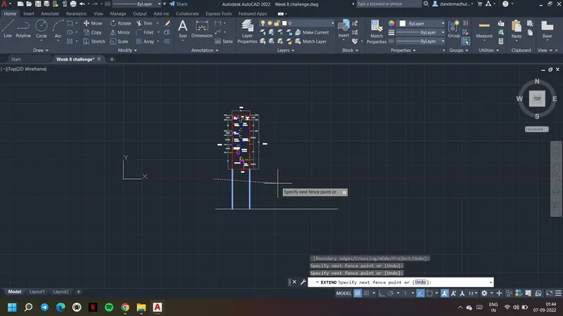
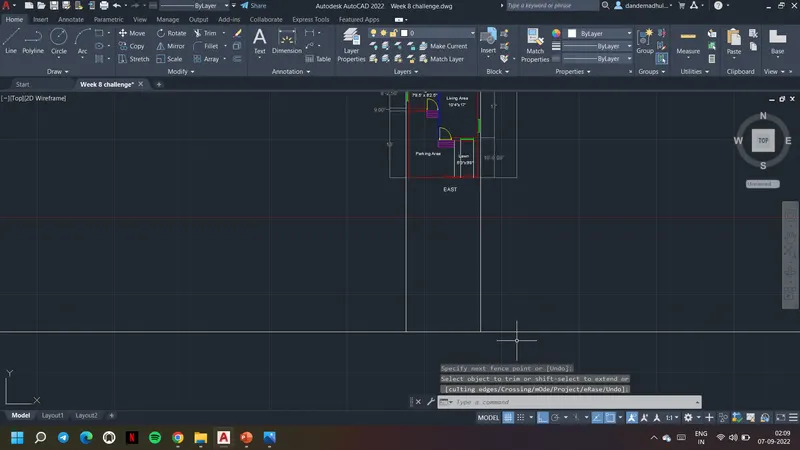
3. A plinth level of 2' is drawn from ground level and then lintel level is drawn at 6' 11" from plinth level.
4. Height of the room is takena s 10'10" and from plinth level it is drawn
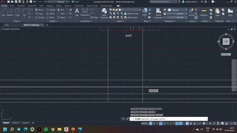
5. Trim all the extra parts using trim command.
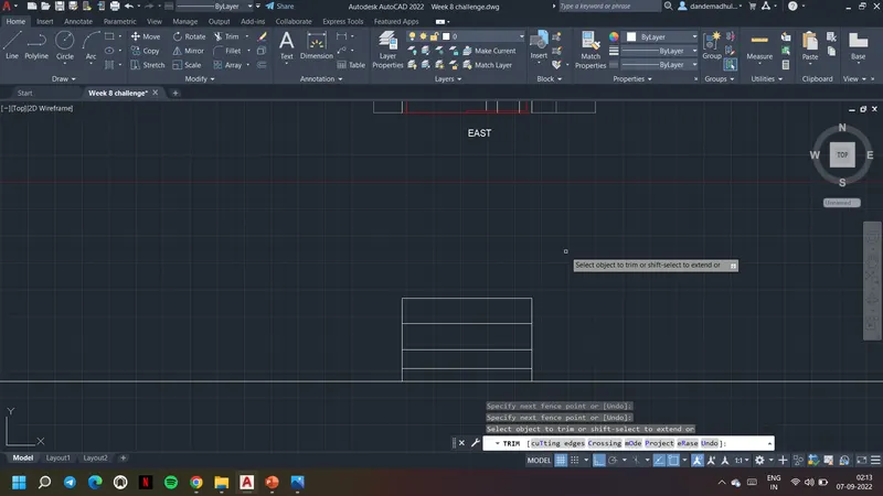
6. Use xline comamnd and draw projections from floor plan as shown
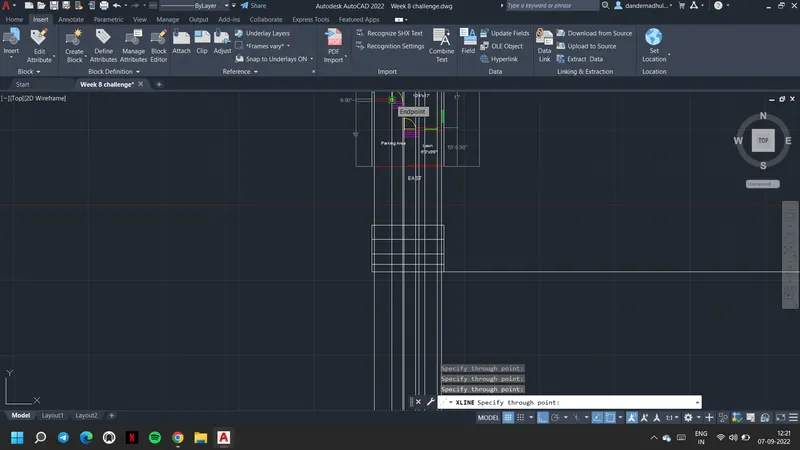
7. Trim all the extra parts using trim command.
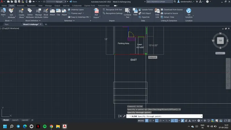
8. Draw the door and window accordingly with the help of projections created.
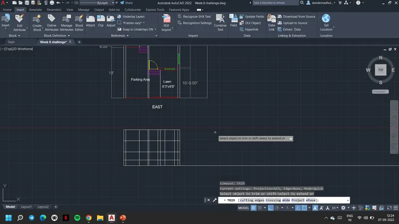
10. Riser of the step is visible in front view elevation. So steps with 7" riser is drawn in the elevation.
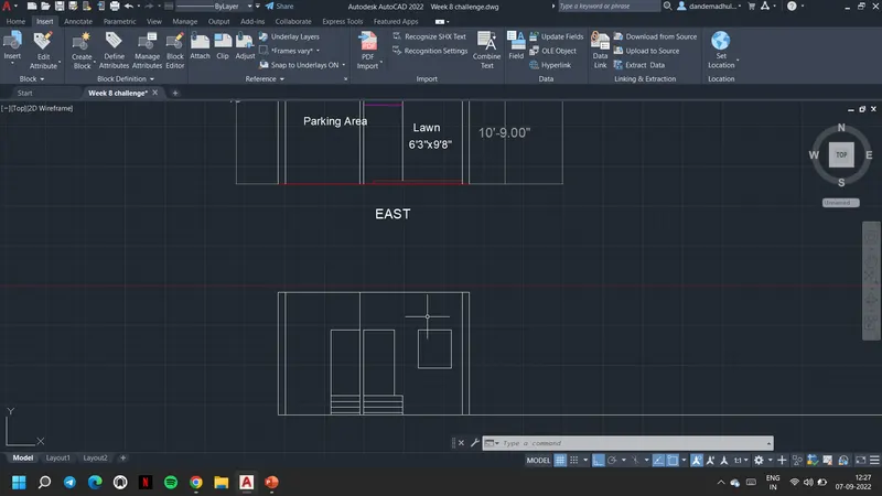
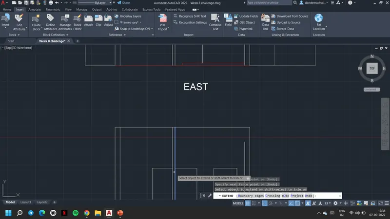
11, Using text comamnd and leader command, text is inserted as shown
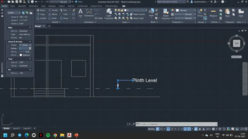
12. Parapet wall of 2'2" is drawn.
Result: b. Architectural Drawing - Elevation
c. Architectural Drawing - Sections.
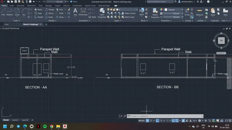
1. Two sections section AA and section BB is taken from the floor plan of the building.
2. First to draw section AA, the floor plan projections are taken using Xline command.
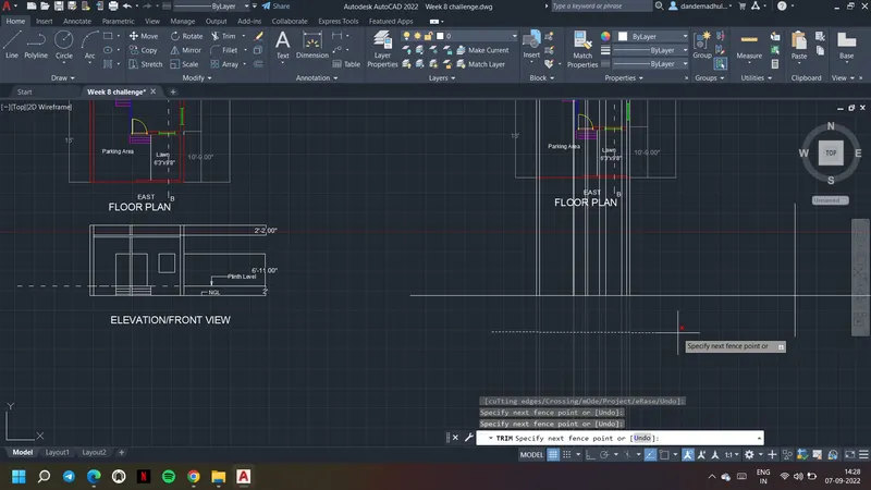
3. Trim the extra parts using trim command.
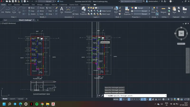
4. At bottom the brick masonry below plinth beam and the plinth beam is drawn as it is sectional view.
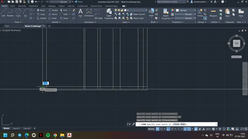
5. The columns are shown in sectional view as mentioned below
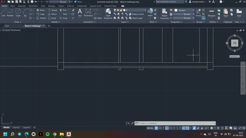
6. For brick masonsry offset comamnd is used and dawn as shown. Else hatch command can also be used.
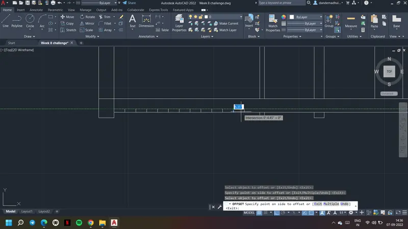
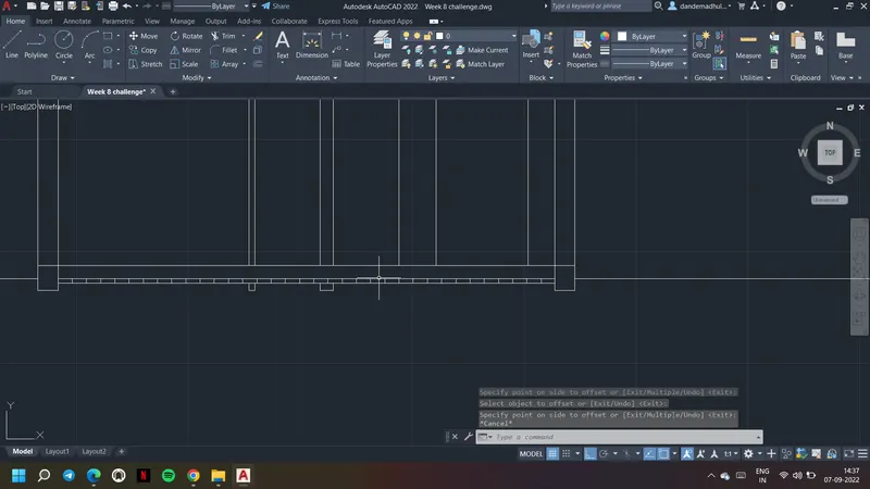
7. Elevation is used and projections are made accordingly using Xline command to form the sectional view.
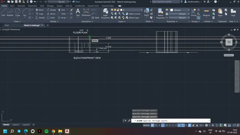
8. Trim command is used to trim the extra parts
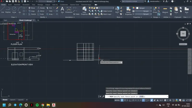
9. Doors and windows are drawn with the help of projections.
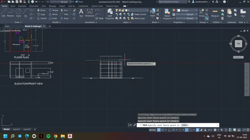
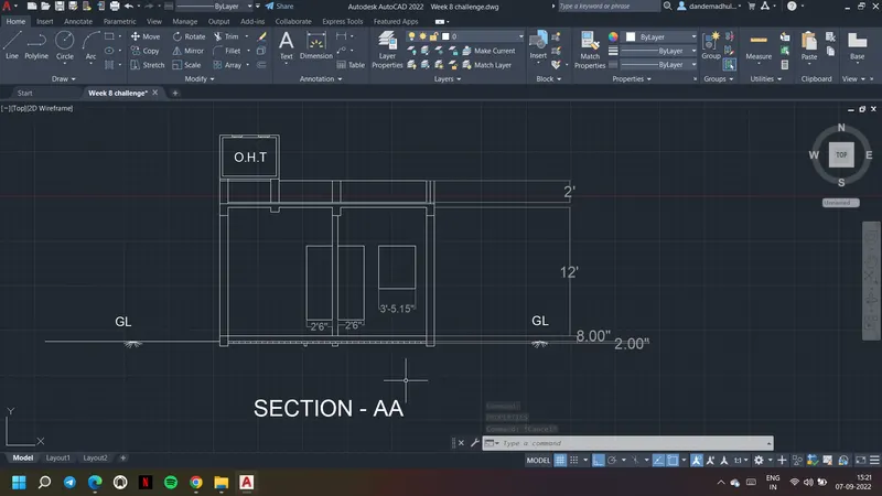
10. Over head tank is drawn above the toilet as shown below.
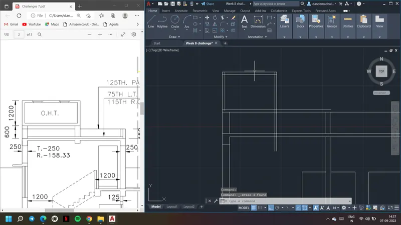
11. Columns are drawn accordingly below the tank.
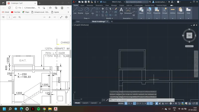
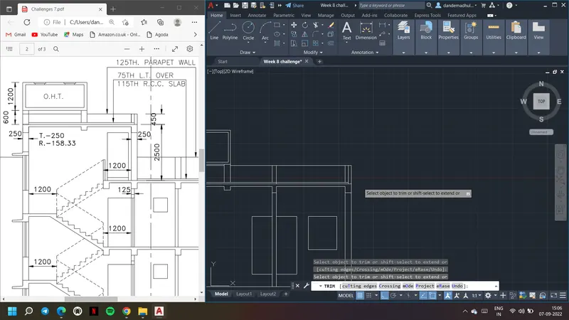
12. Columns sectional view is drawn for every column in the section AA.
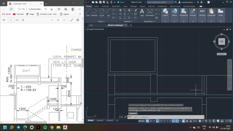
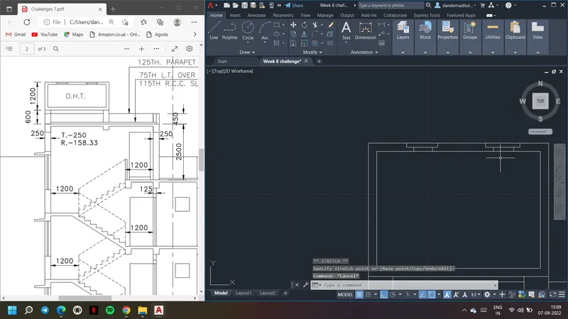
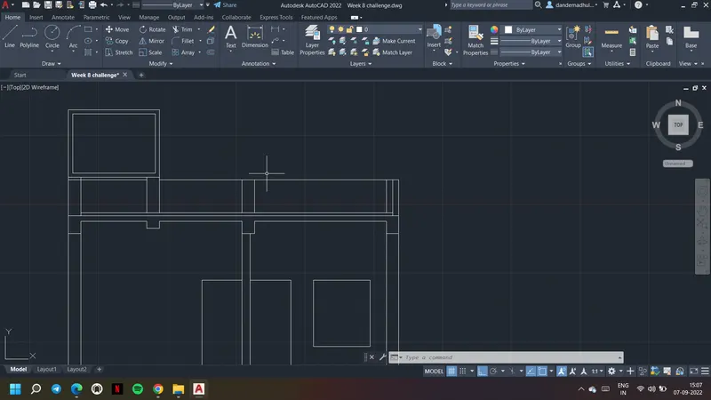
Result: Section AA view of Architectural Drawing
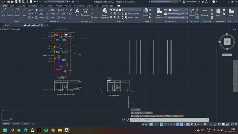
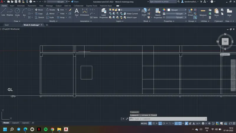
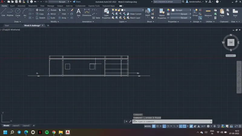
1. For section BB drawing, simialrly project the floor plan as shown.
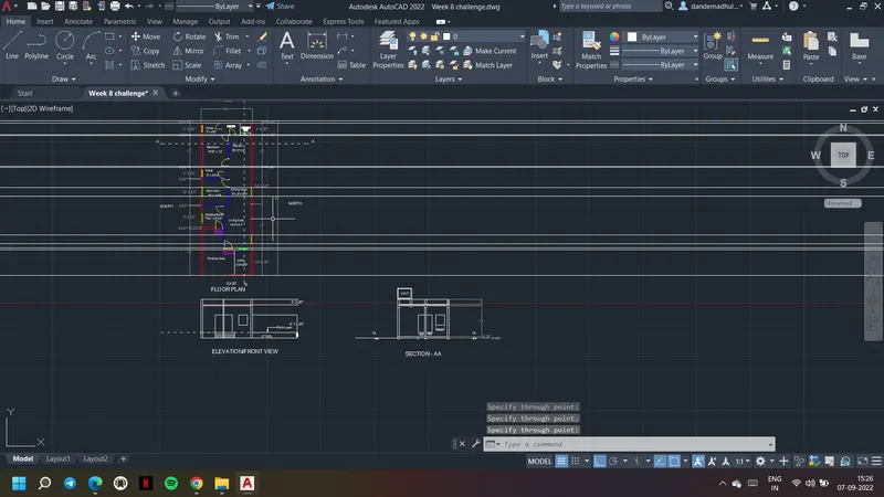
2. Trim the extra parts with the help of trim command.
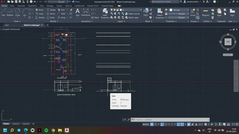
3. Roatate it accordingly to show the sectional view.
 3. Ro
3. Ro
4. Similarly using xline command draw projections from Elevation and finish up the brick masonry.
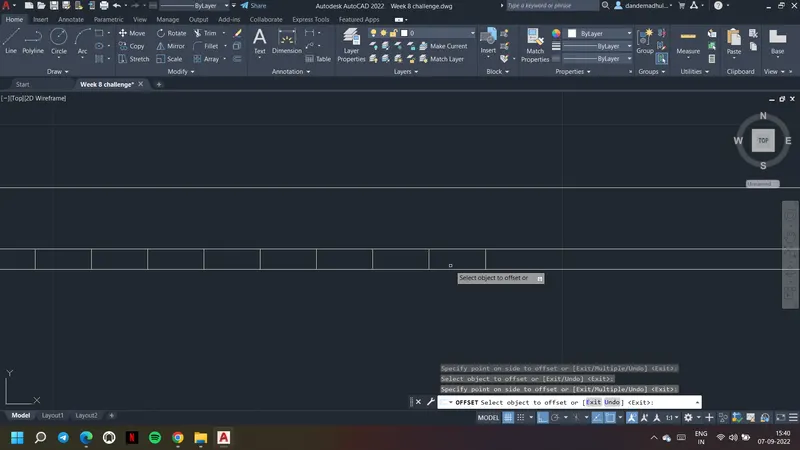
5. Using text commadn insert text to show the ground level
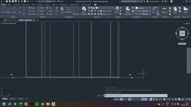
6. As explained in section AA drawing, draw the column sectional view in section BB drawing too.
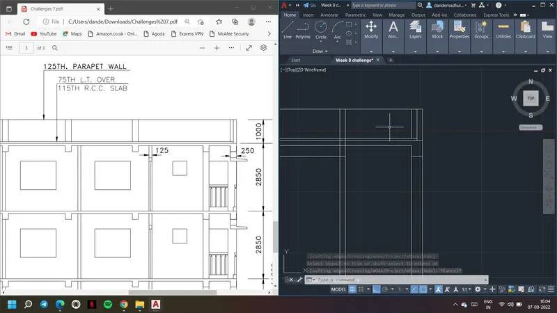
7. Using projections draw the windows.
8. At balcony draw the opening area and the windows.
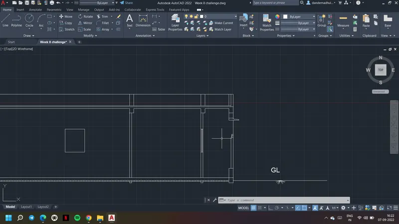
Result: Section BB view of Architectural Drawing
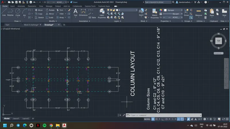
b.Structural Drawing - Column Layout
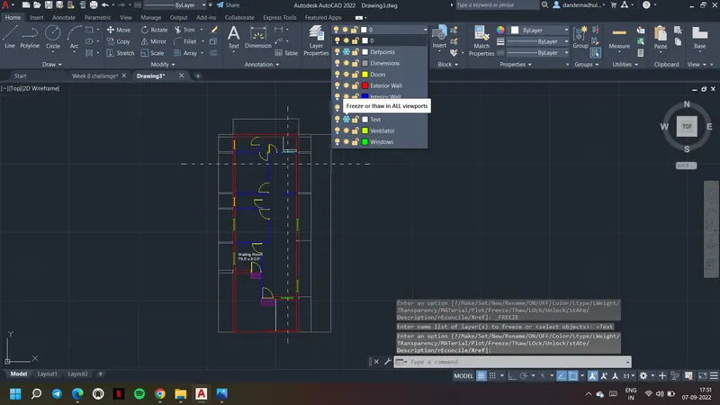
1. First off the layers which are not required.
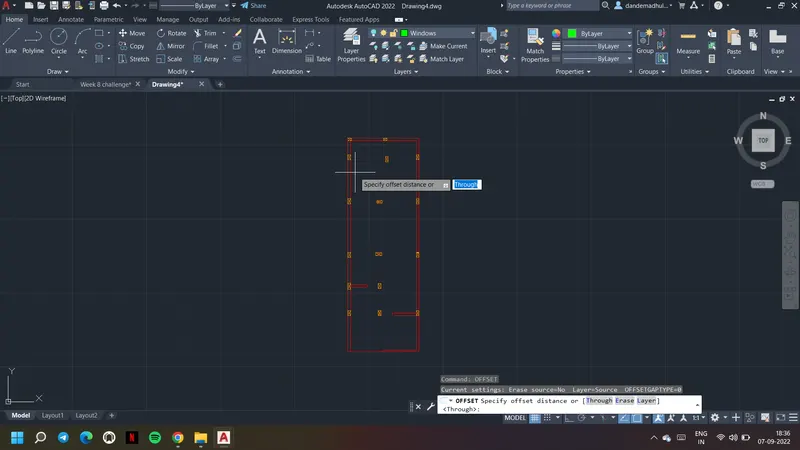
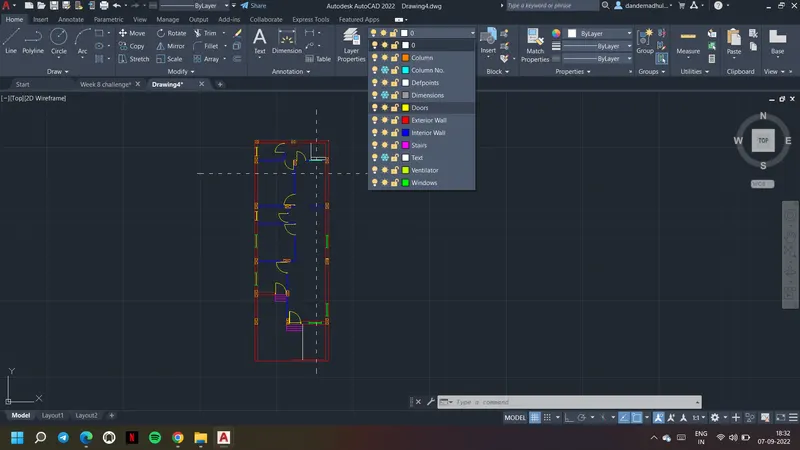
2. Create column, column number layer acoordingly and set column layer as current.
3. Draw the outline of the drawing and using offset command with offset distance 5' draw the outline.
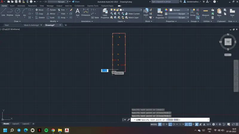
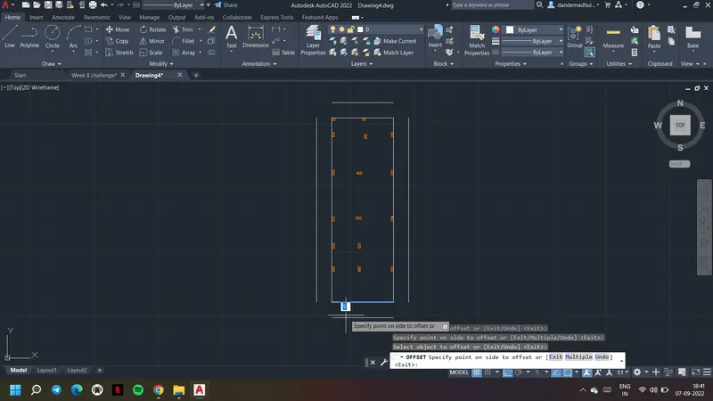
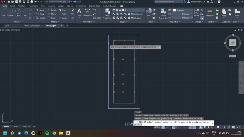
4. Using fillet command join the lines.
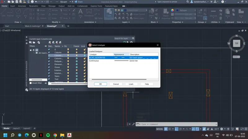
5. Choose column line as dashed line in layers and set it as current
6. At midpoint of every column draw a line in x and y direction.
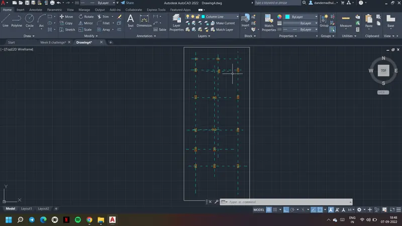
7. Using extend command extend all the drawn column lines to meet the outline.
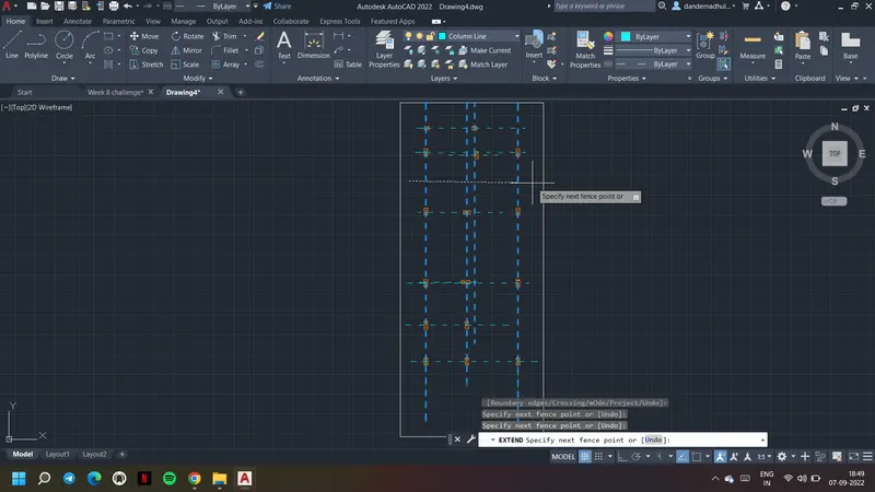
8. Set column number as current and give numbers to each and every column.
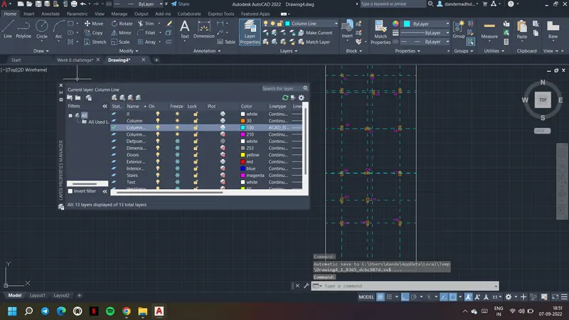
9. Delete the outline and give Text command and using circle command form the text as shown.
10. Copy it and paste at every grid line.
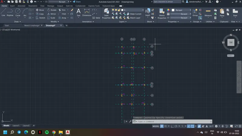
11. Using Tedit edit the text at every grid line
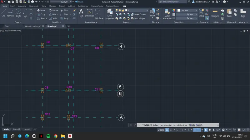
12. Using mirror command mirror the text at every grid line
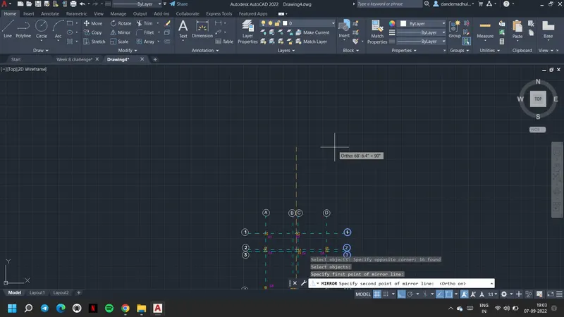
13. Use dimlinear and dimcontinue to insert the dimensions between every grid line.
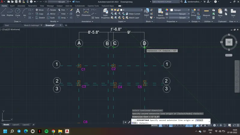
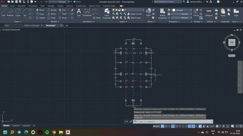
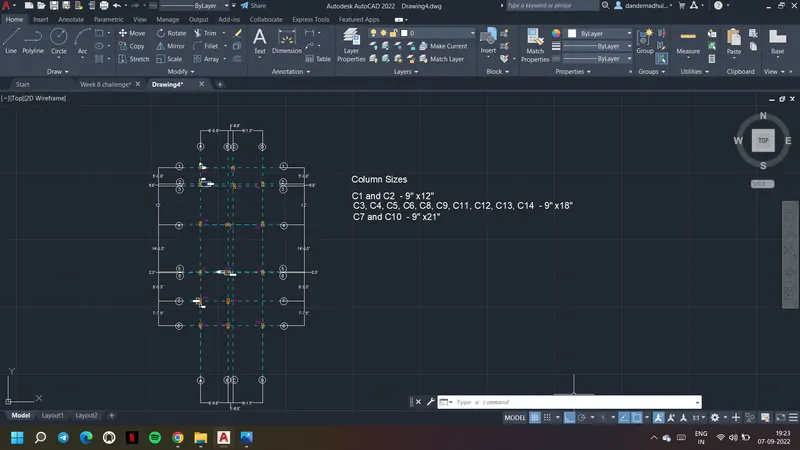
14. Using dimlinear measure the column size.
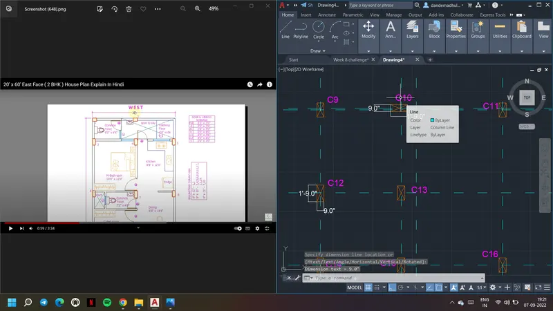
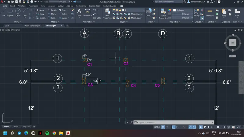
Result: Structural Drawing - Column Layout
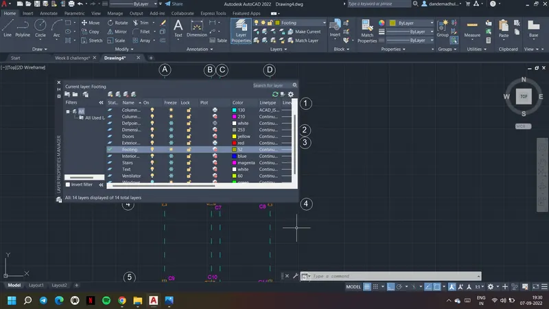
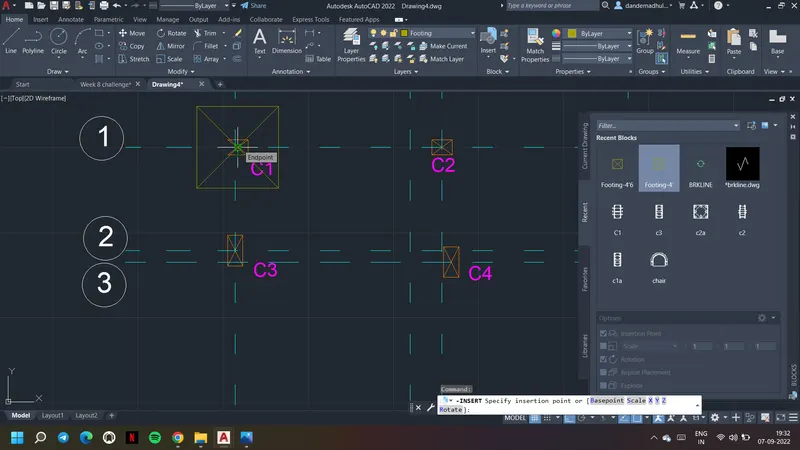
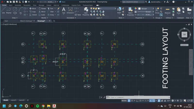
1, To draw footing layout first footing layer is creating and footing number layer is also created
2. Footings of size 4'x4' and 4'6"x4'6" are drawn and formed as blocks using block command
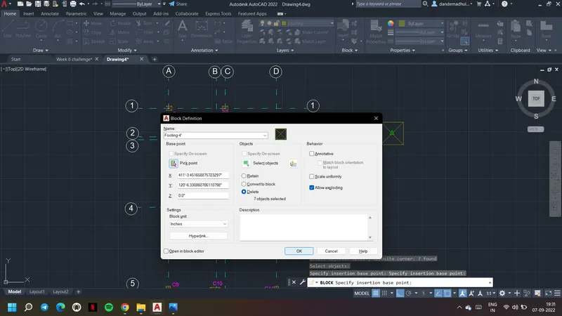
3. Using insert command footings are inserted at each column accordingly.
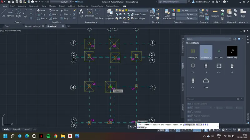
4. Using dimlinear the dimensions of footing is measured.
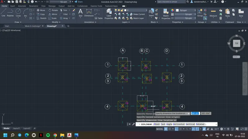
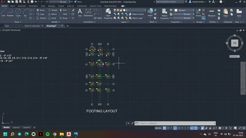
Result: Structural Drawing - Footing Layout
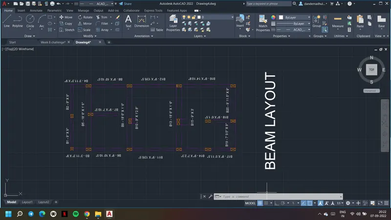
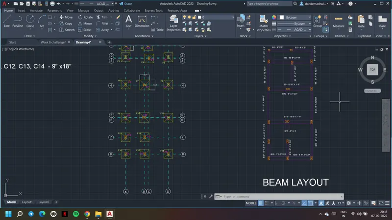
1. To draw beam layout of the given residential building turn off all the layers except exterior wall, interior wall and columns
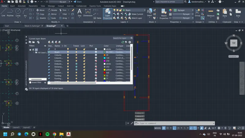
2. Create beam layer and set up the line weight and linetype as dashed line.
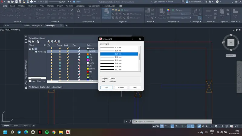
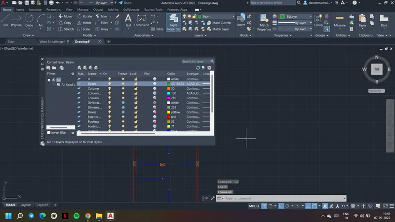
3. Primary and secondary both beams are shown in the drawing. Cantilever beams are also present in this drawing.
4. Beams are drawn accordingly with respect to columns using line command.
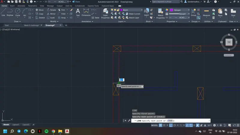
5. Use text command and provide beam number and dimension of the beam for each and evary beam
Result: Structural Drawing - Beam Layout
RESULT:
ARCHITECTURAL DRAWING - FLOOR PLAN, ELEVATION AND SECTIONS
FLOOR PLAN
ELEVATION
SECTION - AA
SECTION - BB
STRUCTURAL DRAWINGS - COLUMN, FOOTING AND BEAM LAYOUT
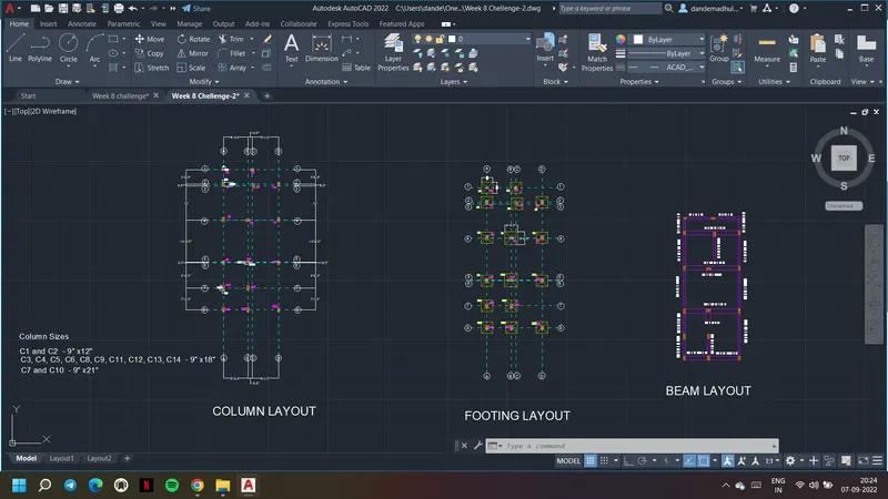
COLUMN LAYOUT
FOOTING LAYOUT
BEAM LAYOUT