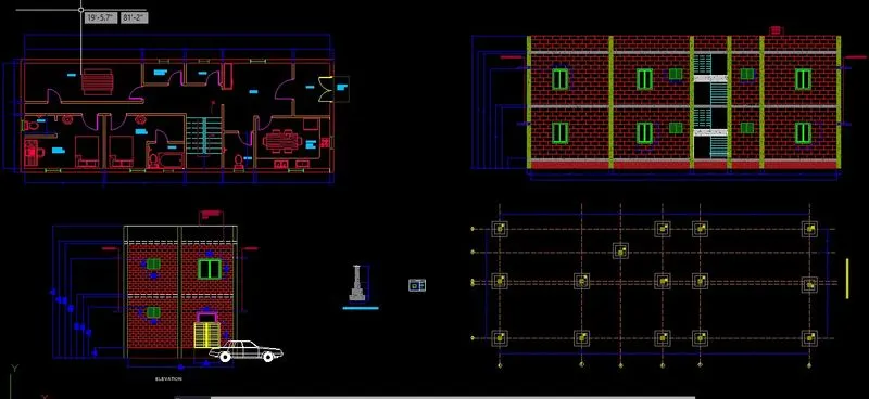
Project 1 _Creating an Architectural plan for the provided plot size and develop relevant basic structural drawings
AIM: To design and draft a layout of residential building using autocad software .
Software used : Autocad
Tools that i have used
Line
circle
arc
polyline
trim
fillet
rectangle
mirror
hatch
copy
move
rotate
mtext
construction line
offset
measure
divide
layers
explode
lengthen
break at point
break
array
dimension
qleader
multi leader
block
insert
express
distance
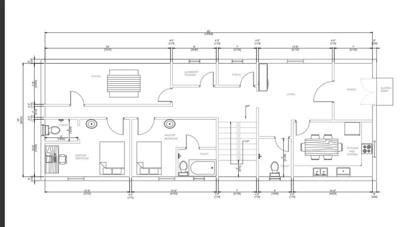
Plot Size: 60’x20’(18.3m x6m) , Orientation- Facing East
1.Architectural Drawing (Floor Plan, Elevations, and Sections)
floor plan:
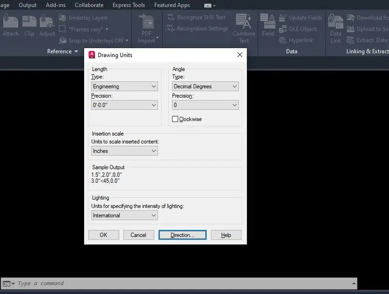
- I have taken the imperial system.
- engineering type.
- set the limmax 200' x 100'. zoom +enter
Take construction line (xline) draw the horizontal line and vertical line.
i started from the south west direction.
take a offset draw the offset line with a distance of 9units it makes the external wall.
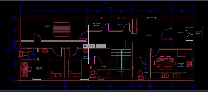
By using offset i made the rooms like master bedroom(2), kitchen and dining ,living room,pooja ,laundary powder,porch and patios (it's not a room).
providing the interior wall thickness of 4.5 units of each room.
i made the different size of door
- main gate-5' x 5'
- main door -4'x 7'
- door 1 -3'x 7'
- door2- 2'7" x 7'
made them in to block by using block command.
And insert them in to opening space which i have provide in the room.
same procedure is repeated in the window and ventilator .
by taking dimension
- window-3' x 4'
- ventilator -2'6"x 2'
For furinature i have gone to autocad design center.
i took the some furniture which i want to place in the rooms.
i go to layer tom take different new layers for
- external wall-red color i have taken.
- internal wall-30 no (orange)
- window-green
- ventilator-94 no
- staircase-cyan
- door-magenta
- furniture -240
- text-140
- sunshade-184
- slab-8
- ramp-68
- gridlines-32
- gridinformation-52
- footing-8
- column-64
- beam-9
- main gate-yellow
- multi leader-244
- plinth-16
and use the layer to their specified elements in the plan.
I go the dimstyles set the data convince to my description.
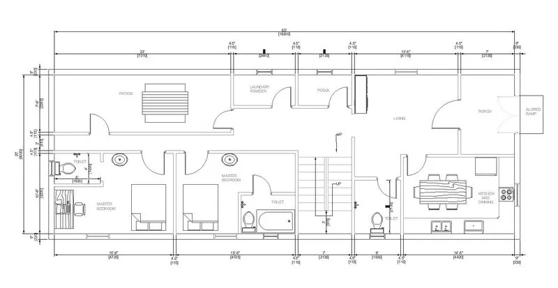
i used the dimlinear, dimcontinous,dimbaseline in the plan for dimensioning.
In obstruction i used the dimspace,dimbreak .
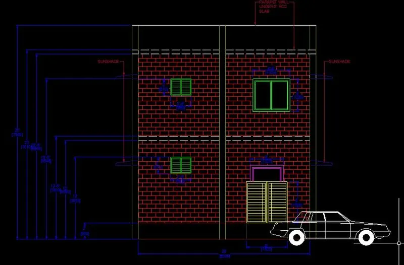
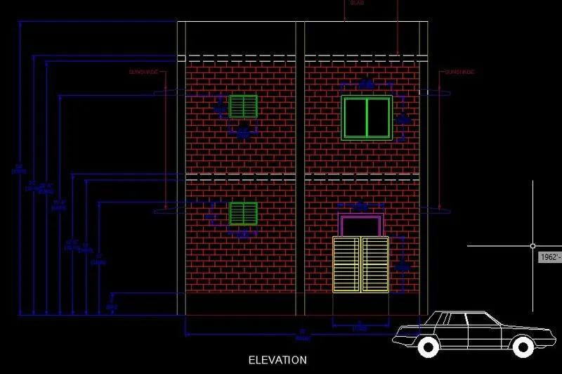
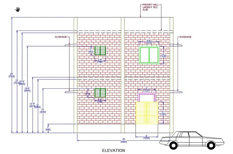
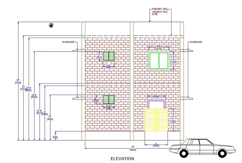
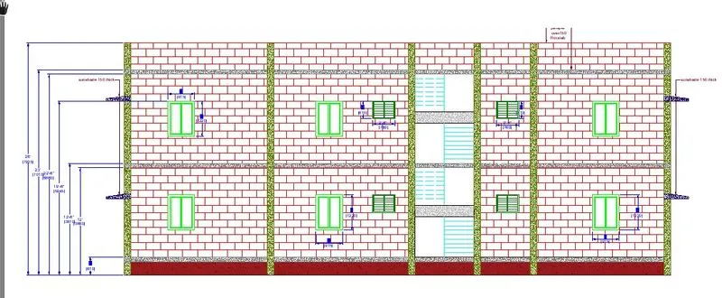
ELEVATION
I projected the front elements by using construction line .
draw the horizontal line to set the elevation.
by using offset i draw the different layers of the front elevation building.
i made the plinth with offset of 2'
i want to show two storey building.
each floor i have taken 10' height.
i draw the main gate by using offset,trim,fillet.
i draw the quater door which we can see in the elevation.
i have draw the door from 2'from the main gate and 3' from the slab.
i provided the ventilator with their dimensions.
in the first floor i have shown the one window and one ventilator.
i take hatch command to show the brick material is used for exterior wall.
i provided the sunshade because in the top view we can see that window and ventilator are in the north and south when we see it in the east side we can see the sunshade.
i provided the car infront of house using adc command.
i show the distinguish the each material (or) element using layer command.
i provided dimensions to the elevation.
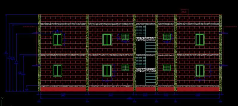
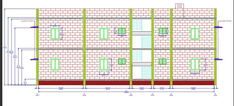
SECTION
i draw an imaginary line in the plan facing towards south.
in the section we can see the all important elements and rooms.
the procedure which i applied in the elevation follow to the section.
in the staircase we can see that beam which is provided for the support.
i provided the parapet wall with the height of 3'.
hatching is done to the section .
dimension are provided to the section.
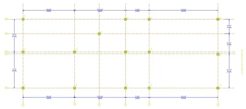
2. Structural Drawing (Column, Bean, Footing Plan)
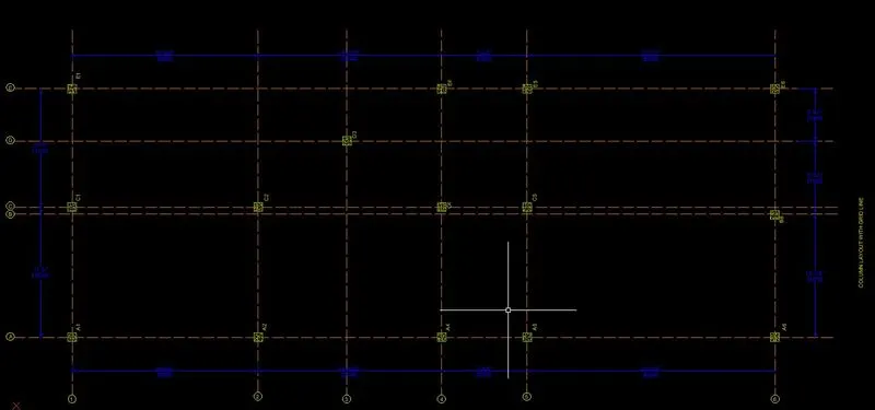
COLUMN: column is the vertical member which distribute the loads to the foundation.
i have taken the column dimension are 9"x9".
in the plan i have provided where it requires.
except that i layoff the remaing elements .
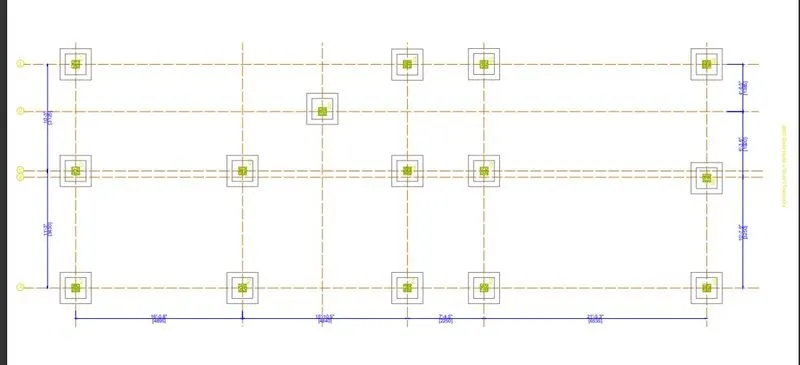
take a line command join the each coumn.
after that take 5' offset provided for the constrains of grid lines.
draw the grid lines by using extension of the column connected lines.
by using text ,copy ,dimedit and express tool are used for column postion and grid information.
dimension are provided to the layout of column.
FOOTING:In the column layout i just have draw the footing .
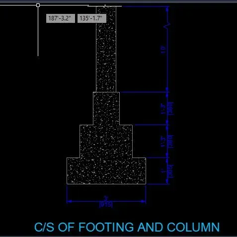
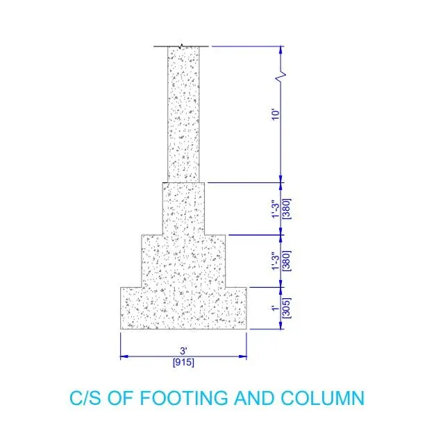
i adopted the stepped footing in this building.
i take dimension for footings are 3'x 3' ,2'x2'.
by using offset i have draw the footings over the column plan.
c/s of footing :
i take 1st footing dimension-3'x 1'
2nd footing -2'x 1'3".
third footing1'x1'3".
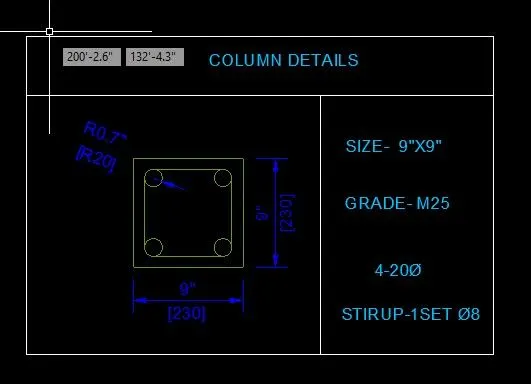
column details:
by using rectangle, offset, circle ,text,copy,textedit and dimension.
size of the column is 9"x9".
grade of concrete is m25
by using text i have written the above.
dimension are provided in to the column reinforcement.
RESULT: I have completed the design and drafting a layout of residential building using autocad software .
units i have taken
plan model
plan in layout print
Elevation view
elevation layout
section model
section layout
column layout
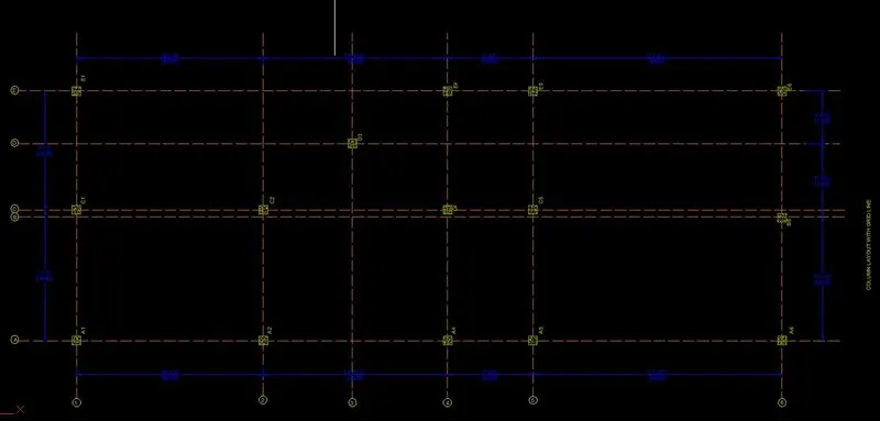
footing plan
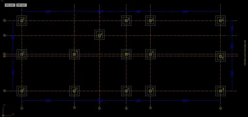
footing layout
overall output layout
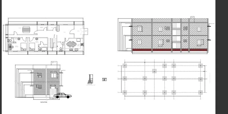
overall output