Project 1 _Creating an Architectural plan for the provided plot size and develop relevant basic structural drawings
Week 8-Assignment 8-Module 2
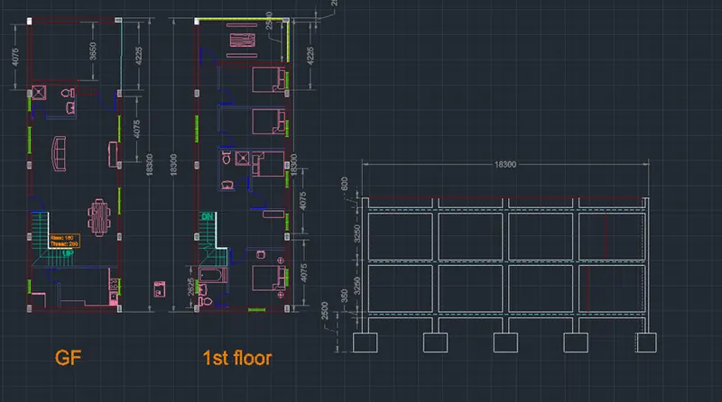
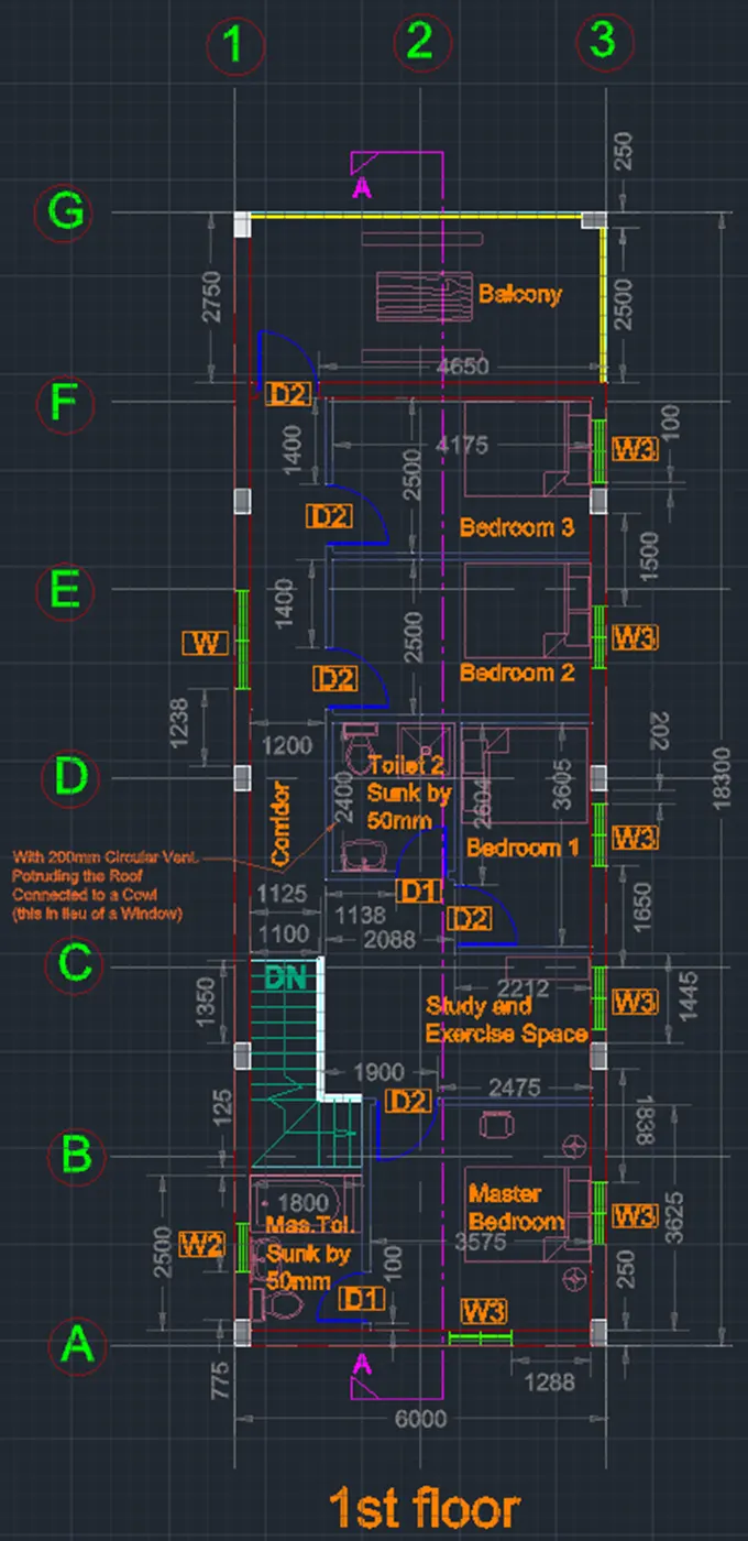
Aim: To Design and Draft a Layout of a Residential Building with a Plot Size of 18.3m x 6m facing east using the proper drawing techniques and editing tools with the aid of AutoCAD.
Introduction:
- Plan, Section and Elevation are different type or view of drawings used in Construction Industry to graphically represent a building design and construction.
- Plan Drawing is drawn from a horizontal plane looking down from above. This is as if you sliced through a space horizontally and stood overlooking down on it.
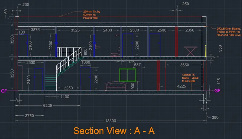
- Section Drawing is drawn from a vertical plane slicing through a building. This is as if you cut through a space vertically and stood directly in front looking straight at it.
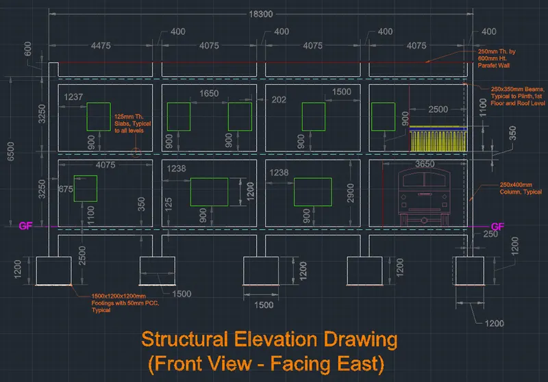
- Elevation Drawing is drawn from a vertical plane looking straight on to a building facade or interior surface. This is as if you directly in front of a building and looked straight at it.
- Architectural Drawing is a sketch, plan, diagram, or schematic that communicates detailed information about the building.
- Structural Drawing, a type of engineering drawing, is a plan or set of plans and details for how a building or other structures will be built.
- Part of the Week 8 lessons were about Blocks, Attributes and manipulation of the Design Center that are essentials in working on this Challenge.
Procedure:
A. Setting the Drawing Parameters;
- Set up the measurement units as metric measured in millimeters.
- To set up that, a much faster way is to type “units” in the command line and hit enter or space bar. The Drawing Units Dialog box will then pop up and measurement parameters will then set up in line with the requirements. Similar thing, you need to set up the dimension through the DDIM command.
- As for the gridlines, you may right click gridline icon in the status bar and go for the drafting settings. Under the Snap and Grid of the Drafting Settings Dialog box, you may set up the needed spacing of grids along its X and Y axis. “DS” command will also work to pop up the Drafting Settings Dialog box.
B. Starting the exercise;
- Combination and manipulation of all the different coordinate entry methods, drawing and modifying tools learned from weeks 1 to 8 were being used here in the completion of all the exercises given and result as pasted below.
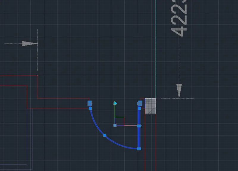
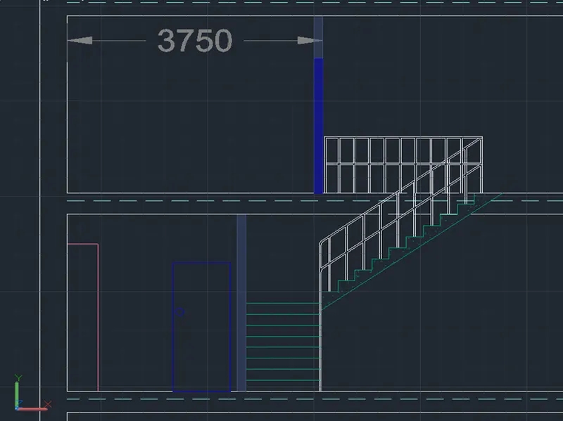
- I have attached some screenshots while plotting the needed Drawings to show the procedure on how it was done to come out with the requested Design layouts.
C. Challenge;
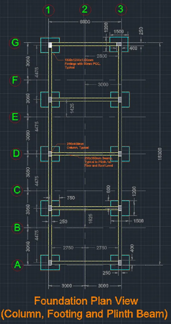
To develop the Architectural (Floor Plan, Elevations and Sections) and Structural Drawings (Column, Beam and Footing),
In general, below commands/functions were being used while working on the Drawings.
- Units
- LIMITS
- DDIM
- XLINE
- LINE
- PLINE
- OFFSET
- DIVIDE
- PTYPE
- MIRROR (MI)
- CIRCLE
- FILLET
- MTEXT
- DTEXT
- MLEADER
- DIM
- DIMCONTINUE
- Manipulation with Ortho mode and Object Snaps
- LAYERS
- UTILITIES
- MATCHPROP
- ANNOTATION
- PDF IMPORT
- RAY
- DIMBREAK
- COPY
- HATCH
- SCALE
- BLOCK/ BLOCK EDIT
- DESIGN CENTER
- ATTRIBUTES
Assumptions:
- Window Sizes;
W = 1600 X 1200
W1 = 1000 X 1100
W2 = 800 X 600
W3 = 1000 X 1200
- Door Sizes;
D = 1200 X 2300
D1 = 850X 2100
D2 = 1000 X 2200
D3 = 1000 X 2200 (wall opening only)
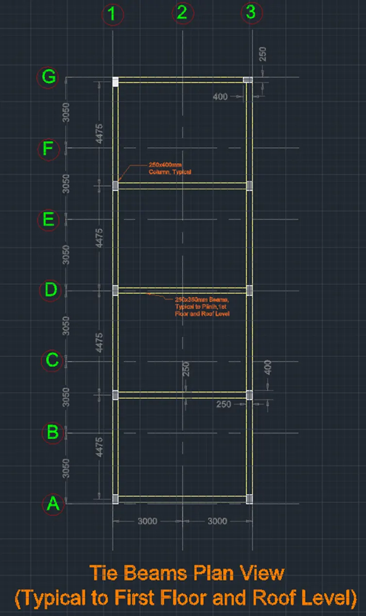
- Column = 250 X 400 (Typical)
- Slab = 125mm Thick
- Beam = 250 X 350 (Typical to Plinth and Tie Beams)
- Footing = 1500 X 1200 X 1200 (Typical with 50mm PCC)
- External Wal = 250mm Thick
- Internal Walls = 125 mm Thick
- Stairs = Riser is 180 and Thread is 250 with 1100 width including railings
- Lintels and Floating Columns are not considered in the drawings.
Below are the brief steps while working on the requested design drawings;
- Set up the limits and layers.
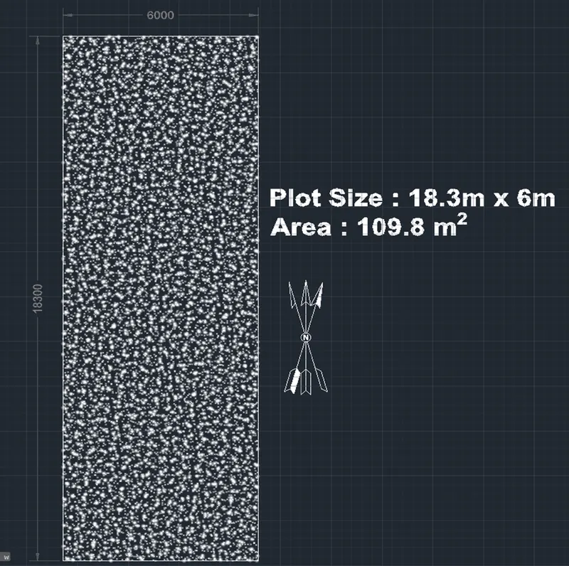
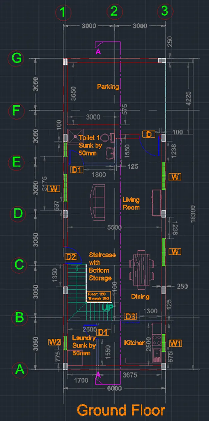
- Plot the lot area with the direction orientation. Draw the lot with a dimension of 6m x 18.3m facing east.
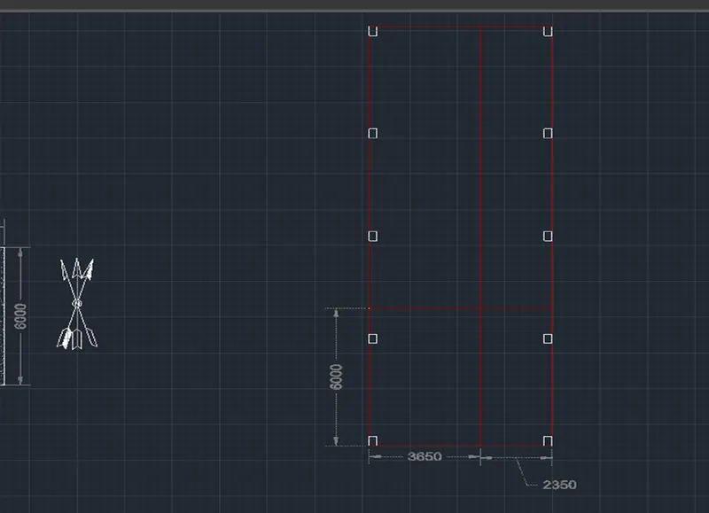
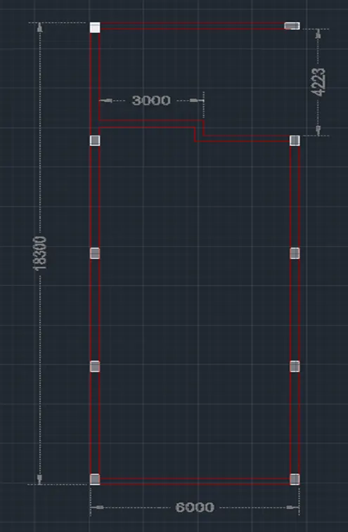
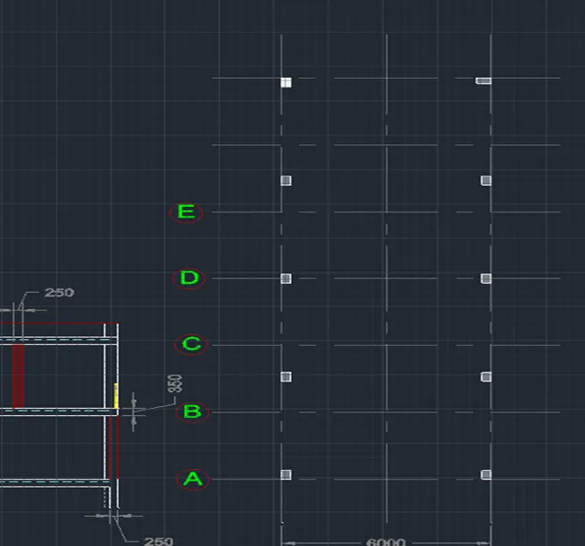
- Using XL command considering orthographic projections, draw the columns and external walls for the Ground Floor inline the design intent.
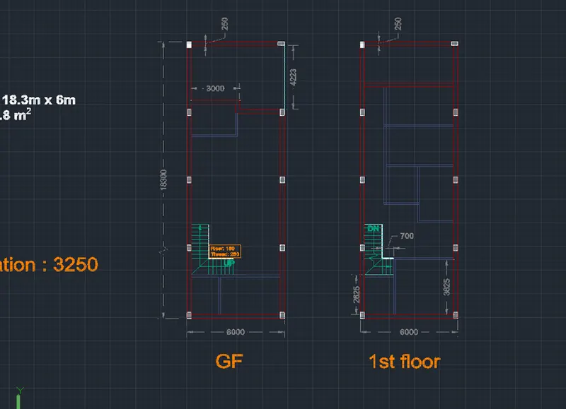
- Construct the room-by-room partitions using the commands; offset, trim, fillet and erase as applicable while maintaining proper layering.
- Proceed with plotting the doors, windows, and staircase.
- You may plot the walls, columns, followed by doors, staircase, and windows.
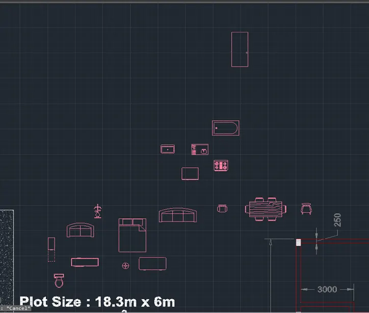
- Its best to use Block for Windows and Doors as grouped for accuracy and speed.
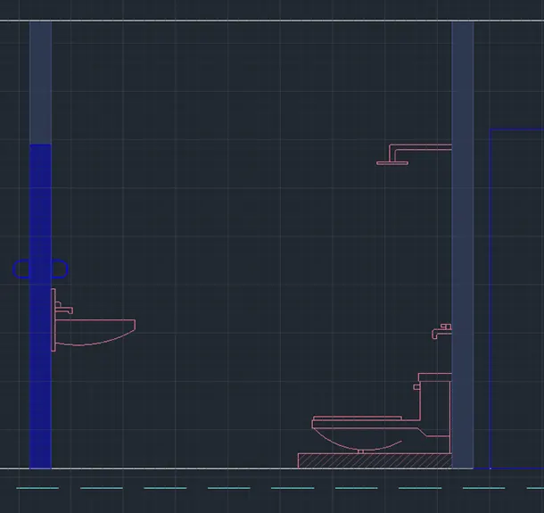
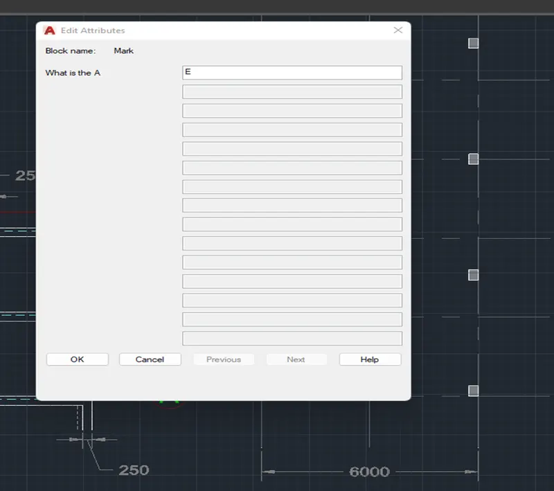
- Furniture, Kitchen Equipment, Toilet Fixtures and Annotations to follow. Its best to use Block and Attributes while working on further detailing on the drawings.
- Almost similar procedure as above for the First Floor with the only difference at Balcony Area having Open walls at two sides with Railing on it.
- Follow it with Section A-A Drawing presented in Architectural Manner.
- Then the Elevation one facing east side considering the Structural of the Building showing section of the foundation footings.
- Rest of the Structural Drawings to follow such as Foundation and Tie Beams Plan Views.