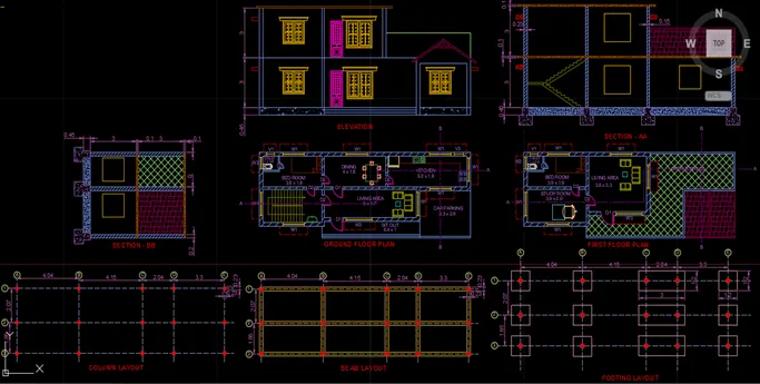
Project 1 _Creating an Architectural plan for the provided plot size and develop relevant basic structural drawings
EAST FACING RESIDENTIAL BUILDING
ARCHITECTURAL AND STRUCTURAL DRAWING
AIM: To create an Architectural plan for the provided plot size and develop relevant structural drawings using AutoCAD.
INTRODUCTION: An Architectural and structural drawing using AutoCAD is created by Lines. The procedure and result should be written after creating An Architectural and structural drawing.
PROCEDURE:
ARCHITECTURAL DRAWINGS
1)PLOT
AIM: To create a plot using AutoCAD.
INTRODUCTION: The plot using AutoCAD is created by Lines. The procedure and result should be written after creating the plot.
STEP 1:
- Open the AutoCAD software and click the start Drawing tab.
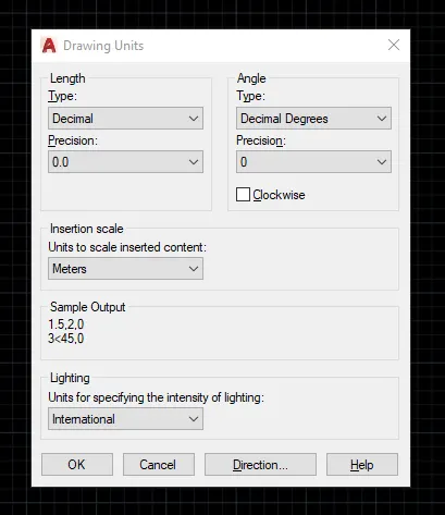
- Enter UNITS in the command box.
- Select DECIMAL in TYPE, 0.0 in PRECISION and METERS in UNITS TO SCALE INSERTED CONTENT. Press OK.
STEP 2:
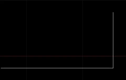
- Enter L in the command box
- Click the first point on the workspace
- Enter 10 as the vertical line
- Enter 20 as a horizontal line
STEP 3:
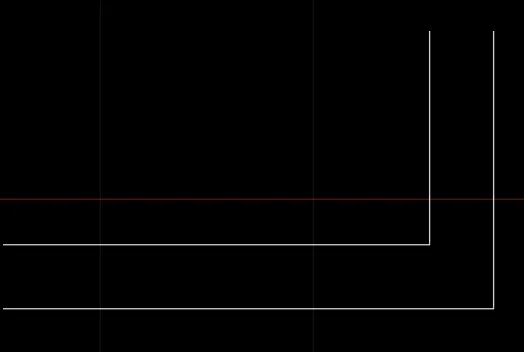
- Enter O in the command box
- Enter 3 as the offset distance
- Select the object and place it at 3 m distance vertically and horizontally
STEP 4:
- Enter L in command box
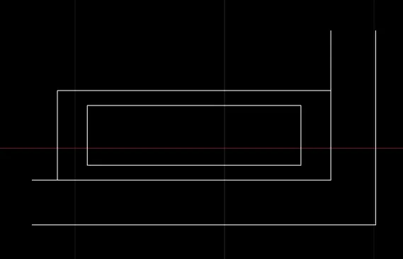
- Enter 18.3 as horizontal point
- Enter 6 as vertical point
- Enter 2 as offset distance
- Select the object and make offset horizontally
- Enter O in command box
- Enter 1 as offset distance
- Select the object and make offset horizontally
- Enter TR in command box
- Delete the unwanted lines
STEP 5:
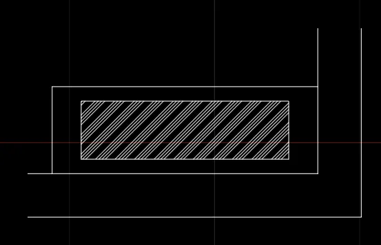
- Enter H in command box
- Select ANSI34 hatch pattern in ribbon
- Enter 0.05 in scale in ribbon
- Click pick point
- Click the rectangular box to be hatched
STEP 6:
- Enter DIMS in command box
- Click MODIFY. In SYMBOLS and ARROWS, Enter ARROW SIZE as 200.
- In TEXT, Enter TEXT HEIGHT as 0.2.
- In PRIMARY UNITS, Click DECIMAL in UNIT FORMAT, 0.00 in PRECISION.
- In LINES, enter 0.05 as EXTEND BEYOND LINES and 0 as OFFSET FROM ORIGIN. Click OK.
- Click SET CURRENT. Click CLOSE.
- Click DIMENSIONS AND TEXT dropdown in LAYER.
- Enter DIML in command box and drag the dimensions.
- Enter DT in command box. Enter 0.2 as TEXT HEIGHT and 0 as TEXT ROTATION ANGE.
- Enter TEXT.
- Enter CO in command box. Copy the text and place it in another location.
- Enter TEXTEDIT in command box. Using this, editing in text can be done.
- Click the layers to give their properties in diagrams
- Save the drawing and rename it as AUTOCAD CHALLENGE 8
RESULT:
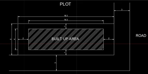
The Plot is created by lines using AutoCAD. The step-by-step procedure for plot is also explained. The Dimension is also entered in the diagram.
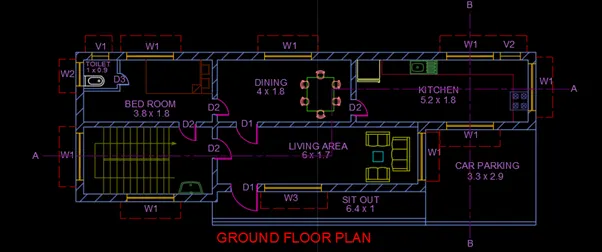
2)GROUND FLOOR PLAN
AIM: To create ground floor plan using AutoCAD.
INTRODUCTION: Ground floor plan using AutoCAD is created by Lines. The procedure and result should be written after creating ground floor plan
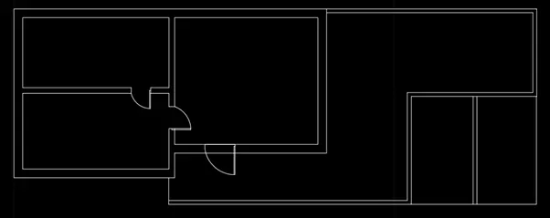
STEP 1:
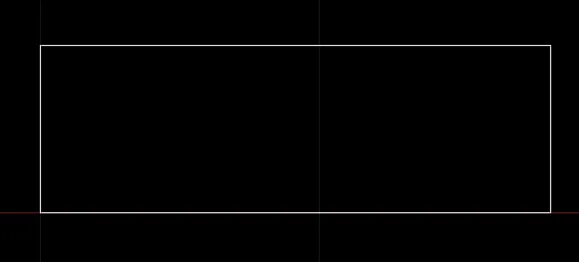
- Enter L in command box
- Enter 0,0 as first point
- Enter @14.3,0 as next point
- Enter @0,4 as next point
- Enter @-14.3,0 as next point
- Enter @0, -4 as next point
- Click ENTER or CLOSE in command box
STEP 2:
- Enter O in command box
- Enter 0.23 as offset distance
- Select the 4 horizontal and vertical lines and place it inwards
- Click ENTER
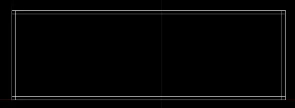
STEP 3:
- Enter O in command box
- Enter 0.38 as offset distance
- Select the inner left side line and place the offset line inwards
- Enter O in command box
- Enter 0.15 as offset distance
- Select the 0.38m line and place the offset line behind
- Enter O in command box
- Enter 4 as offset distance
- Select 0.15m line and place the offset line behind
- Enter O in command box
- Enter 6 as offset distance
- Select 0.15m line and place the offset line behind
- Enter O in command box
- Enter 0.15 as offset distance
- Select 4m and 6m lines and place the offset line behind
- Enter O in command box
- Enter 2 as offset distance
- Select the inner lower side line and place the offset line inwards
- Enter O in command box
- Enter 0.15 as offset distance
- Select 2m line and place the offset line behind
- Press ENTER
- Enter TR in command box
- Delete the lines of 4m in lower half part
- Press ENTER
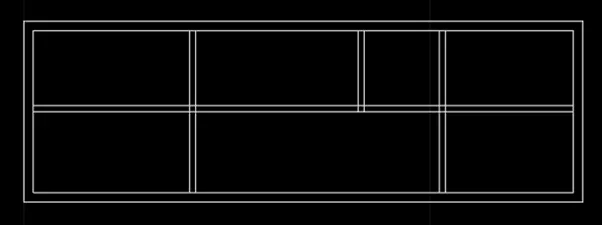
STEP 4:
- Enter L in command box
- Enter @0,0.23 as first point
- Enter @0.15,0 as next point
- Enter @0, -0.23 as first point
- Enter @-0.15,0 as next point
- Enter CO in command box
- Copy the rectangle and place at 0.8 m distance
- Press ENTER
- Enter L in command box
- Click the midpoint of rectangle
- Enter @0.05,0 as next point
- Enter @0,1 as next point
- Press ENTER
- Enter C in command box
- Click the lower corner of right rectangle and click the other rectangle’s lower right corner point
- Connect the 2 rectangles
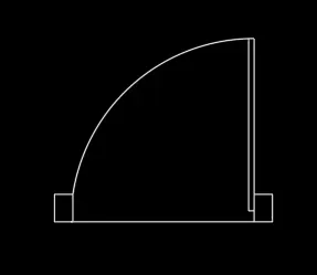
STEP 5:
- Enter B in command box
- Pick midpoint of the door
- Select the door
- Enter DOOR in Name
- Click OK
- Enter BE in command box
- Click PARAMETER
- Click FLIP and pick the point in door
- Click ACTION
- Select the door
- Click TEST BLOCK and test it
- Again, follow the above step for another flip
- Click CLOSE BLOCK
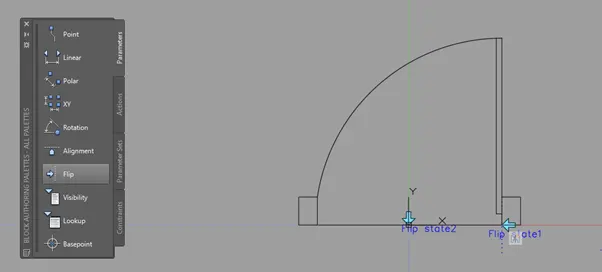
STEP 6:
- Enter I in command box
- Select DOOR in Name
- Enter 270 in angle
- Click OK
- Place the door in every part of the lines
- Enter SC in command box
- Select the doors except 3.8 m line and 2nd part of horizontal room
- Enter 0.8 in SCALE FACTOR
- Enter TR in command box
- Delete the unwanted lines
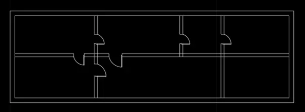
STEP 7:
- Enter L in command box
- Track the line in lower inside horizontal line and enter 0.6
- Connect to the upper horizontal line
- Enter O in command box
- Enter 2 as offset distance
- Select the 0.6m line and place the offset behind
- Press ENTER
- Enter O in command box
- Enter 0.2 as offset distance
- Select the 0.6m line and place the offset behind
- Press ENTER
- Repeat the above step for 8 more times
- Press ENTER
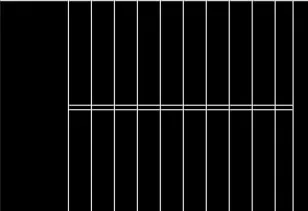
STEP 8:
- Enter L in command box
- Click the point in workspace
- Enter @0.5,0 as next point
- Enter @0,1 as next point
- Enter @-0.5,0 as next point
- Enter @0, -1 as next point
- Enter O in command box
- Enter 0.07 as offset distance
- Select lower, right and upper lines and place the offset line inwards
- Enter O in command box
- Enter 0.28 as offset distance
- Select the upper inner line and place behind
- Repeat the above step one more time
- Enter B in command box
- Enter 3seater sofa in NAME
- Pick midpoint of sofa
- Select the object
- Click DELETE
- Press OK
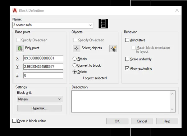
STEP 9:
- Enter L in command box
- Click the point in workspace
- Enter @0.7,0 as next point
- Enter @0,0.5 as next point
- Enter @-0.7,0 as next point
- Enter @0, -0.5 as next point
- Enter O in command box
- Enter 0.07 as offset distance
- Select lower, right and left lines and place the offset line inwards
- Enter O in command box
- Enter 0.28 as offset distance
- Select the upper inner line and place behind
- Enter B in command box
- Enter 2seater sofa in NAME
- Pick midpoint of sofa
- Select the object
- Click DELETE
- Press OK
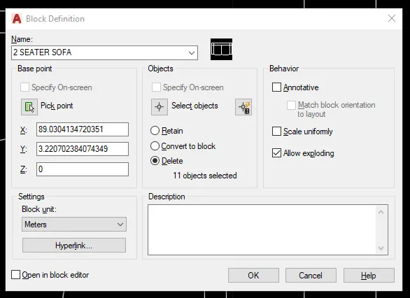
STEP 10:
- Enter I in command box
- Select 3seater sofa and press OK
- Place it at the required place
- Enter I in command box
- Select 2seater sofa and press OK
- Place it at the required place
- Enter I in command box
- Select 2seater sofa and enter 180 as angle. Press OK
- Place it at the required place
- Enter REC in command box
- Click DIMENSIONS
- Enter 0.3 as length
- Enter 0.3 as width
- Place it at the required place
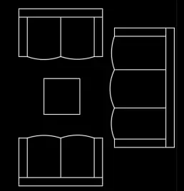
STEP 11:
- Enter L in command box
- Click the point in command box
- Enter @0.80,0 as next point
- Enter @0,1 as next point
- Enter @-0.80,0 as next point
- Enter @0, -1 as next point
- Press ENTER
- Enter L in command box
- Click the point in command box
- Enter @0,0.14 as next point
- Enter @2,0 as next point
- Enter @0, -0.14 as next point
- Press ENTER
- Enter ARC in command box
- Click 1st and 2nd point in rectangle
- Enter F in command box
- Enter 0.05 as radius
- Select the corners to make arc
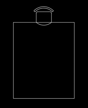
STEP 12:
- Enter B in command box
- Enter dining table chair in NAME
- Pick point of dining chair
- Select object
- Select DELETE
- Press OK
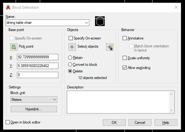
STEP 13:
- Enter I in command box
- Select dining table chair
- Enter 90 in angle
- Click OK
- Place it at 2 positions in left side of table
- Enter I in command box
- Select dining table chair
- Enter 270 in angle
- Click OK
- Place it at 2 positions in right side of table
- Enter I in command box
- Select dining table chair
- Enter 180 in angle
- Click OK
- Place it at lower side of table
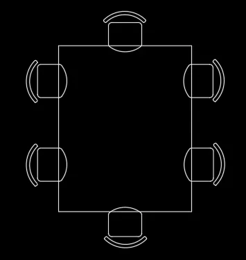
STEP 14:
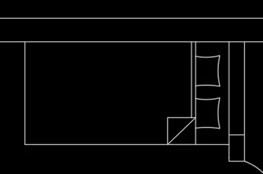
- Enter L in command box
- Track the line and enter @0, -1 as first point
- Enter @-2,0 as next point
- Enter @0,1 as next point
- Press ENTER
- Enter O in command box
- Enter 0.32 as offset distance
- Enter O in command box
- Enter 0.04 as offset distance
- Switch off ORTHOMODE
- Click it at 0.3m distance and connect it at horizontal place
- Switch on ORTHOMODE
- Connect those with line
- Enter L in command box
- Enter @0.24,0 as first point
- Enter @0,0.3 as next point
- Enter @-0.24,0 as first point
- Enter @0, -0.3 as next point
- Enter ARC in command box
- Create arcs on four side
- Enter TR in command box
- Delete the unwanted lines
- Enter M in command box
- Move the pillow at required place
- Enter CO in command box
- Copy the pillow and place it at required place
STEP 15:
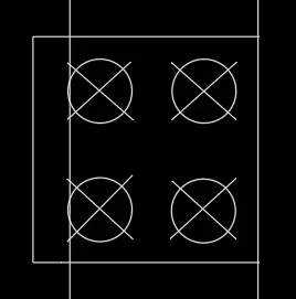
- Enter L in command box
- Enter @0.54,0 as first point
- Enter @0,0.54 as next point
- Enter @-0.54,0 as first point
- Press ENTER
- Enter C in command box
- Enter 0.08 as diameter
- Switch off ORTHOMODE
- Draw diagonal lines in the circle
- Enter CO in command box
- Copy the circle and place it at 3 required places
- Press ENTER
STEP 16:
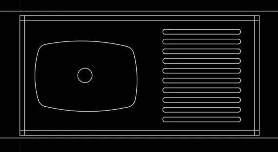
- Enter L in command box
- Enter @-0.45,0 as first point
- Enter @0,1.42 as next point
- Enter @-3.93,0 as next point
- Enter @0,0.45 as next point
- Enter O in command box
- Enter 0.85 as offset distance
- Place the line inwards
- Enter O in command box
- Enter 0.01 as offset distance
- Place the line inwards
- Enter O in command box
- Enter 0.41 as offset distance
- Place the line inwards
- Enter O in command box
- Enter 0.81 as offset distance
- Place the line inwards
- Enter O in command box
- Enter 0.01 as offset distance
- Place the line inwards on four sides
- Enter L in command box
- Enter @0.24,0 as first point
- Enter @0,0.01 as next point
- Enter @-0.24,0 as first point
- Enter @0, -0.01 as next point
- Enter ARC in command box
- Create arcs on both sides
- Enter CO in command box
- Click ARRAY and enter 9
- Click FIT and place those at appropriate place
- Enter REC in command box
- Enter 0.3 as length
- Enter 0.2 as width
- Enter ARC in command box
- Create arcs on four sides
- Enter TR in command box
- Delete all the unwanted lines
- Enter C in command box
- Enter 0.02 as diameter
- Press ENTER
STEP 17:
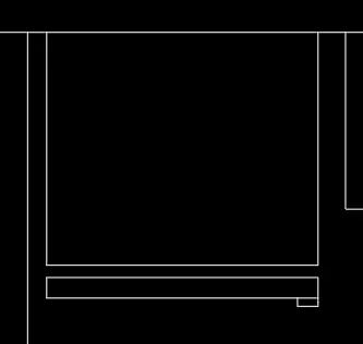
- Enter L in command box
- Enter @-0.07,0 as first point
- Enter @0, -0.57 as next point
- Enter @-0.66,0 as next point
- Enter @0,0.57 as next point
- Enter O in command box
- Enter 0.03 as offset distance and place it behind
- Enter O in command box
- Enter 0.05 as offset distance and place it behind
- Close the rectangle with lines
- Enter L in command box
- Click the right lower corner point
- Enter @0, -0.02 as next point
- Enter @-0.05,0 as next point
- Enter @0,0.02 as next point
- Press ENTER
STEP 18:
- Switch off ORTHOMODE
- Enter L in command box
- Click the wall and make an inclined line
- Switch on ORTHOMODE
- Enter @0.49,0 as first point
- Enter F in command box
- Enter 0.05 as fillet radius
- Click corners and make curves
- Enter O in command box
- Enter 0.1 as offset distance
- Click the 3 sides of the object
- Place the offset line
- Enter L in command line
- Enter 0.05 as first point
- Enter C in command box
- Enter 0.02 as radius
- Enter L in command box
- Click on the circle
- Enter 0.05 as next point
- Press ENTER
- Enter O in command box
- Enter CO in command box
- Copy the circle and place at 0.05m distance
- Enter C in command box
- Enter 0.03 as radius
- Enter M in command box
- Move it to appropriate place
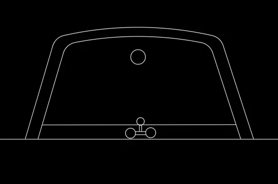
STEP 19:
- Enter L in command box
- Enter @1,0 as first point
- Enter @0, -0.9 as next point
- Enter @-1,0 as next point
- Press ENTER
- Enter O in command box
- Enter 0.07 as offset distance
- Place the line on right and lower side
- Enter I in command box
- Enter Door in Name
- Enter 270 in angle. Press OK.
- Enter SC in command box
- Enter 0.5 as scale factor
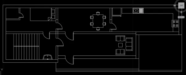
STEP 20:
- Enter L in command box
- Click the inner wall
- Enter @0.5,0 as next point
- Enter @0,0.3 as next point
- Enter @-0.5,0 as next point
- Press ENTER
- Enter L in command box
- Enter 0.05 as first point
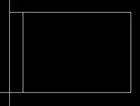
- Enter ARC in command box
- Create arcs in rectangle
- Enter O in command box
- Enter 0.1 as offset distance
- Select the upper, lower and right line and arc
- Enter F in command box
- Enter 0.1 as fillet radius
- Select the arc and lines
- Copy the arc and mirror the arc
- Enter M in command box
- Move it at appropriate place
- Enter C in command box
- Enter 0.02 as radius
- Move it at required place
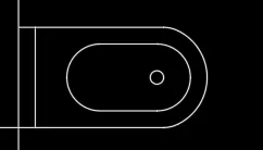
STEP 21:
- Enter L in command box
- Click on the outer wall and connect it to inner wall
- Enter O in command box
- Enter 1.40 as offset distance
- Place at 1.40 m distance
- Enter O in command box
- Enter 0.10 as offset distance
- Place at 0.10 m distance
- Enter O in command box
- Enter 0.03 as offset distance
- Place at 0.03 m distance
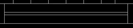
- Enter L in command box
- Enter @0, -0.2 as first point
- Enter @-0.5,0 as next point
- Enter @0,2 as next point
- Enter @0,0.2 as next point
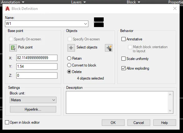
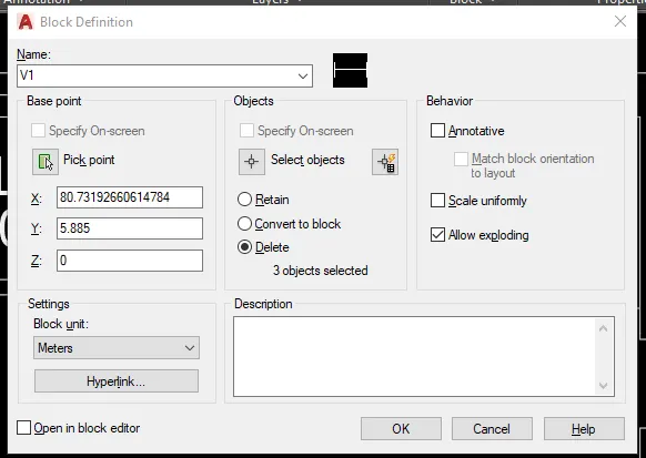
- Enter B in command box
- Enter W1 and create a block
- Enter O in command box
- Enter 0.5 as offset distance
- Place at 0.5 m distance
- Enter O in command box
- Enter 0.10 as offset distance
- Place at 0.10 m distance
- Enter O in command box
- Enter 0.03 as offset distance
- Place at 0.03 m distance
- Enter L in command box
- Enter @0, -0.2 as first point
- Enter @-0.5,0 as next point
- Enter @0,1 as next point
- Enter @0,0.2 as next point
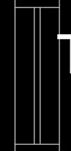
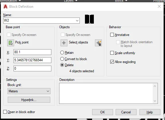
- Create a block named W2
- Enter L in command box
- Connect two walls
- Enter O in command box
- Enter 0.3 as offset distance
- Connect the midpoint
- Enter L in command box
- Enter @0, -0.2 as first point
- Enter @-0.5,0 as next point
- Enter @0,0.8 as next point
- Enter @0,0.2 as next point
- Enter L in command box
- Connect two walls
- Enter O in command box
- Enter 0.4 as offset distance
- Connect the midpoint
- Enter H in command box
- Select ANSI34 and enter 0.05 as scale factor
- Enter DIMS in command box
- Click MODIFY. In SYMBOLS and ARROWS, Enter ARROW SIZE as 200.
- In TEXT, Enter TEXT HEIGHT as 0.2.
- In PRIMARY UNITS, Click DECIMAL in UNIT FORMAT, 0.00 in PRECISION.
- In LINES, enter 0.05 as EXTEND BEYOND LINES and 0 as OFFSET FROM ORIGIN. Click OK.
- Click SET CURRENT. Click CLOSE.
- Click DIMENSIONS AND TEXT dropdown in LAYER.
- Enter DIML in command box and drag the dimensions.
- Enter DT in command box. Enter 0.2 as TEXT HEIGHT and 0 as TEXT ROTATION ANGE.
- Enter TEXT.
- Enter CO in command box. Copy the text and place it in another location.
- Enter TEXTEDIT in command box. Using this, editing in text can be done.
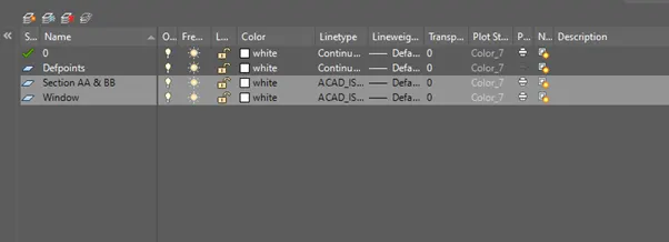
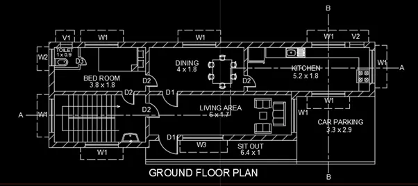
- Enter L in command box
- Draw the vertical and horizontal line
- Click the layers to give their properties in diagrams
STEP 22:
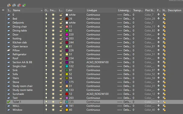
- Enter LAYER in command box
- Click NEW LAYER
- Enter Bed, Dining table, Dining table chair, Door, Footing, Open terrace, Pillow, Refrigerator, Sink, Sofa, Stove, Stairs etc with Colours
- Click the appropriate object with colours
RESULT:
The Ground Floor Plan is created by lines using AutoCAD. The step-by-step procedure for Ground floor plan is also explained. The Dimension is also entered in the diagram.
3)FIRST FLOOR PLAN
AIM: To create first floor plan using AutoCAD.
INTRODUCTION: The First-floor plan using AutoCAD is created by Lines. The procedure and result should be written after creating the first-floor plan.
STEP 1:
- Copy the ground floor plan after creating walls and doors
- Enter L in command box
- Enter @-3.3,0 as first point
- Enter @0, -2.85 as next point
- Enter O in command box
- Enter 1.57 as offset distance
- Place it at 1.57 m distance
- Enter O in command box
- Enter 0.01 as offset distance
- Place it at 0.01 m distance
STEP 2:
- Enter REC in command box
- Click DIMENSIONS in command box
- Enter 0.30 as length
- Enter 0.30 as width
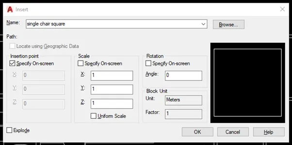
- Enter B in command box
- Enter single chair square in NAME
- Click OK
- Enter I in command box
- Place at required place
STEP 3:
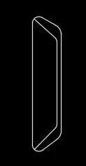
- Enter L in command box
- Enter @0.56,0 as first point
- Enter @0,0.13 as next point
- Enter @-0.56,0 as first point
- Enter @0, -0.13 as next point
- Enter F in command box
- Enter 0.05 as fillet radius
- Select the corners and make curves
- Switch off ORTHOMODE
- Draw the line and switch on ORTHOMODE
STEP 4:
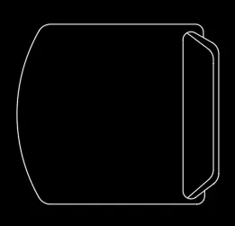
- Enter L in command box
- Click centre of the object
- Enter@0, 0.05 as next point
- Enter @-0.54,0 as next point
- Enter @0, -0.67 as next point
- Enter @0.54,0 as next point
- Enter ARC in command box
- Create curves of the chair
- Enter F in command box
- Enter 0.05 as fillet radius
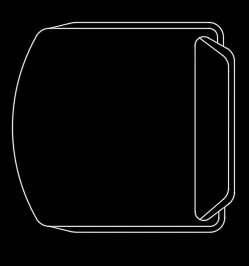
- Enter O in command box
- Enter 0.03 as offset distance
- Select the line and create offset line
- Repeat the above step one more time
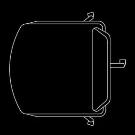
STEP 5:
- Enter L in command box
- Enter @0.2,0 as first point
- Enter @0, -0.05 as next point
- Enter @-0.2,0 as first point
- Enter @0, 0.05 as next point
- Enter ARC in command box
- Create curves of the object
- Switch off ORTHOMODE
- Enter 0.03 as first point
- Enter 0.03 as next point
- Connect it to the object
- Repeat the same step for two other stands by creating inclined lines
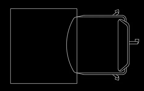
STEP 6:
- Enter L in command box
- Enter @0.80,0 as first point
- Enter @0,0.90 as next point
- Enter @-0.80,0 as first point
- Enter @0, -0.90 as next point
- Press ENTER
STEP 7:
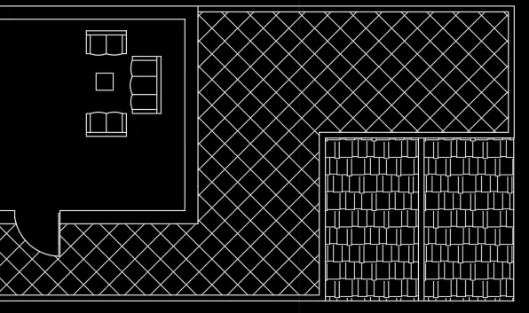
- Enter H in command box
- Click ANSI37 pattern and enter 0.1 as scale factor
- Select the object and place the hatch
- Enter H in command box
- Click AR-RSHKE pattern and enter 0.05 as scale factor
- Select the object and place the hatch
- Enter I in command box
- Select 3seater sofa, 2seater sofa and single chair square and press OK
- Place those at appropriate position
STEP 8:
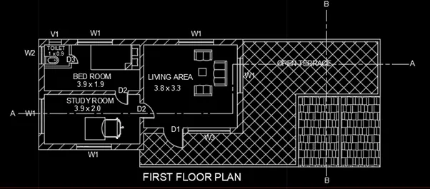
- Insert the windows, bed, toilet, study room chair and study room table
- Copy section AA and section BB. Place it.
- Click DIMENSIONS AND TEXT dropdown in LAYER.
- Enter DIML in command box and drag the dimensions.
- Enter DT in command box. Enter 0.2 as TEXT HEIGHT and 0 as TEXT ROTATION ANGE.
- Enter TEXT.
- Enter CO in command box. Copy the text and place it in another location.
- Enter TEXTEDIT in command box. Using this, editing in text can be done.
STEP 9:
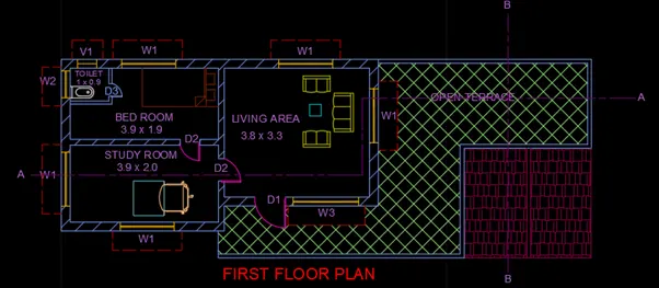
- Click LAYER PROPERTIES
- Select the required names and their colours
- Select the objects and place it.
RESULT:
The First Floor Plan is created by lines using AutoCAD. The step-by-step procedure for First floor plan is also explained. The Dimension is also entered in the diagram.
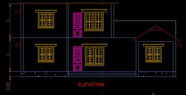
4)ELEVATION
AIM: To create an elevation using AutoCAD.
INTRODUCTION: An Elevation using AutoCAD is created by Lines. The procedure and result should be written after creating an elevation.
STEP 1:
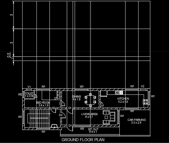
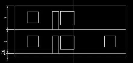
- Enter L in command box
- Extend the walls, windows and doors from Ground floor plan
- Press ENTER
- Enter L in command box
- Connect outer to outer wall
- Enter O in command box
- Enter 0.5 as offset distance
- Select the lower line and place at 0.5m line
- Enter O in command box
- Enter 3 as offset distance
- Select the 0.5m line and place at 3m line
- Repeat the above step one more time
STEP 2:
- Enter L in command box
- Enter @0,0.8 as first point
- Enter @-1.4,0 as next point
- Press ENTER
- Enter O in command box
- Enter 1.4 as offset distance
- Press ENTER
- Repeat the above step for first floor
- Enter L in command box
- Enter @0,2.22 as first point
- Repeat the above step for first floor
- Enter L in command box
- Enter @0,0.8 as first point
- Enter @-1.7,0 as next point
- Press ENTER
- Enter O in command box
- Enter 1.7 as offset distance
- Press ENTER
- Repeat the above step for first floor
- Enter L in command box
- Enter @0,0.8 as first point
- Enter @-1.4,0 as next point
- Press ENTER
- Enter O in command box
- Enter 1.4 as offset distance
- Press ENTER
- Enter TR in command box
- Delete the unwanted lines
STEP 3:
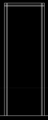
- Enter O in command box
- Enter 0.04 as offset distance
- Select the left line and right line and create offset line
- Enter O in command box
- Enter 0.02 as offset distance
- Select the left line and right line and create offset line
STEP 4:
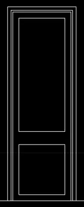
- Enter O in command box
- Enter 0.07 as offset distance
- Select the 4 side lines and click inwards
- Enter O in command box
- Enter 0.57 as offset distance
- Select the lower line and click inwards
- Enter O in command box
- Enter 0.15 as offset distance
- Select the 0.57 m line and click inwards
- Enter TR in command box
- Delete the extruded lines
STEP 5:
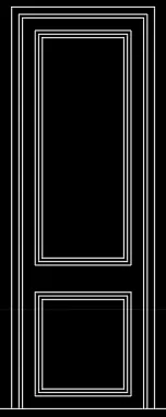
- Enter O in command box
- Enter 0.02 as offset distance
- Select the 4 side lines of large rectangle and click inwards
- Again, do it one more time
- Repeat the same step for small rectangle
STEP 6:
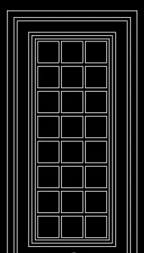
- Enter REC in command box
- Enter 0.01 as first corner point
- Enter 0.13 as second corner point
- Enter CO in command box
- Place at 0.01m distance
- Repeat it one more time
- Enter CO in command box
- Click ARRAY in command box
- Enter 7 as number of items
- Click FIT
STEP 7:
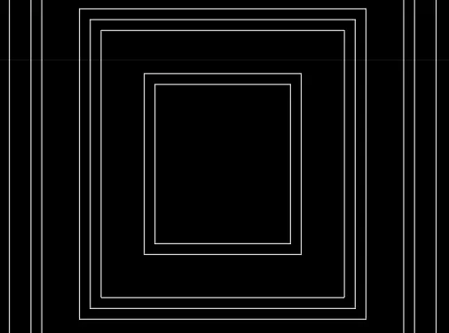
- Enter O in command box
- Enter 0.08 as offset distance
- Select 4 sides and create offset lines
- Enter O in command box
- Enter 0.02 as offset distance
- Select 4 sides and create offset lines
STEP 8:
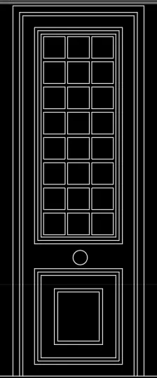
- Enter C in command box
- Enter 0.04 as radius
- Enter M in command box
- Move the circle between 2 rectangles
STEP 9:
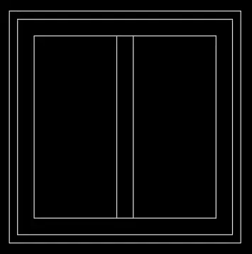
- Enter O in command box
- Enter 0.05 as offset distance
- Select 4 sides and create offset line
- Enter O in command box
- Enter 0.60 as offset distance
- Select left and right inner line and create offset line
- Enter TR in command box
- Delete the extruded lines
STEP 10:
- Enter O in command box
- Enter 0.09 as offset distance and select left and upper line
- Enter O in command box
- Enter 0.22 as offset distance
- Enter O in command box
- Enter 0.54 as offset distance
- Enter CO in command box
- Copy the rectangle and place at required places
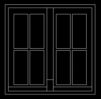
STEP 11:
- Enter O in command box
- Enter 0.07 as offset distance
- Select the lower line and create offset line
- Enter L in command box
- Enter 0.18 as first point
- Press ENTER
- Enter L in command box
- Enter 0.2 as first point
- Enter 0.2 as next point
- Enter 0.80 as next point
- Enter 0.2 as next point
- Enter O in command box
- Enter 0.02 as offset distance\
- Select the line and create offset line
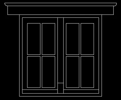
STEP 12:
- Enter B in command box
- Enter Window 1 in NAME
- Pick midpoint of window
- Select the object
- Press OK
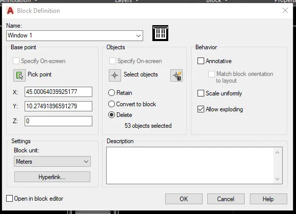
STEP 13:
- Enter B in command box
- Enter Door 1 in NAME
- Pick midpoint of door
- Select the object
- Press OK
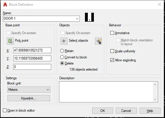
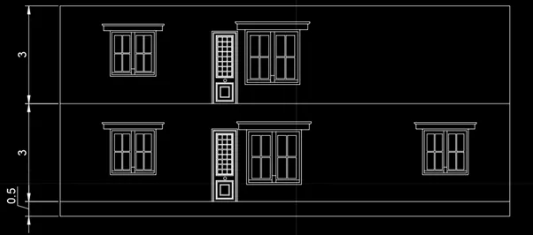
STEP 14:
- Enter I in command box
- Enter Window1 and press OK
- Place it at required place
- Enter I in command box
- Enter Door1 and press OK
- Place it at required place
- Enter I in command box
- Enter Window2 and press OK
- Place it at required place
- Enter SC in command box
- Enter 1.2 as scale factor
STEP 15:
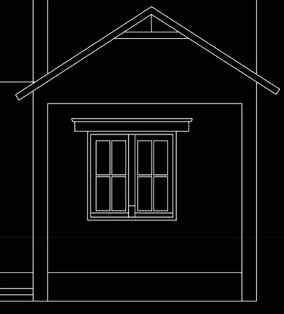
- Switch off ORTHOMODE
- Enter L in command box
- Create the line at midpoint
- Enter O in command box
- Enter 0.1 as offset distance
- Enter MI in command box
- Select the object and create a mirror
- Switch on ORTHOMODE
- Enter L in command box
- Create the line
- Click at midpoint and connect it at other point
STEP 16:
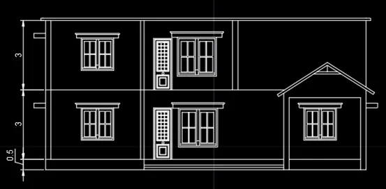
- Enter L in command box
- Enter 0.15 as first point
- Enter O in command box
- Enter 0.15 as offset distance
- Create the offset line
- Enter L in command box
- Click on the wall
- Enter 0.5 as first point
- Enter 0.2 as next point
- Enter 0.5 as next point
- Enter CO in command box
- Copy the sunshade and place at 2 positions
STEP 17:
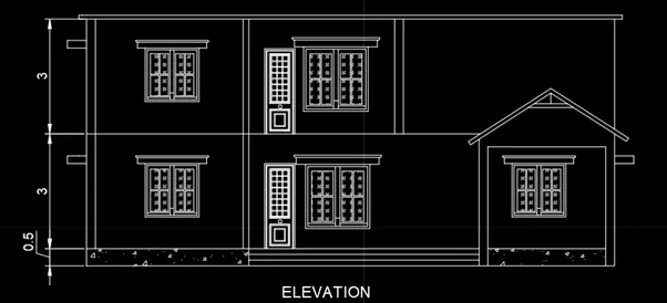
- Enter H in command box
- Click AR-CONC pattern
- Enter 0.01 in scale
- Enter H in command box
- Click GOST-GLASS pattern
- Enter 0.03 in scale
- Click the windows and create hatch pattern
- Click DIMENSIONS AND TEXT dropdown in LAYER.
- Enter DIML in command box and drag the dimensions.
- Enter DT in command box. Enter 0.2 as TEXT HEIGHT and 0 as TEXT ROTATION ANGE.
- Enter TEXT.
- Enter CO in command box. Copy the text and place it in another location.
- Enter TEXTEDIT in command box. Using this, editing in text can be done.
STEP 18:
- Click the layer properties
- Select windows, sunshade, door, roof, text and dimension
- Apply the appropriate colours
RESULT:
The Elevation is created by lines using AutoCAD. The step-by-step procedure for Elevation is also explained. The Dimension is also entered in the diagram.
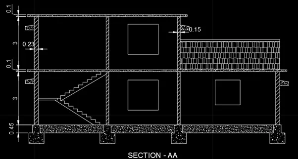
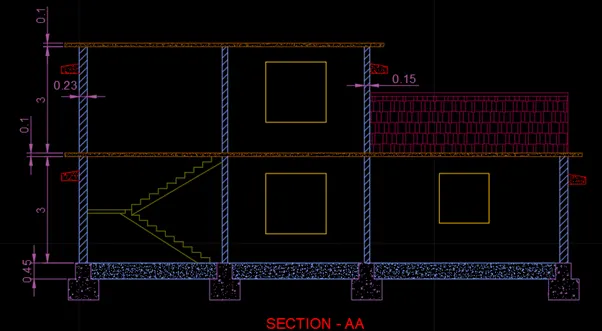
5)SECTION AA
AIM: To create a section-AA using AutoCAD.
INTRODUCTION: A section-AA using AutoCAD is created by Lines. The procedure and result should be written after creating a section-AA.
STEP 1:
- Enter L in command box
- Extend all the lines from Elevation and first floor plan
- Extend outer to outer wall, plinth and roof lines
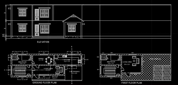
STEP 2:
- Enter TR in command box
- Delete the extruded lines
- Enter O in command box
- Enter 0.23 as offset distance
- Select right and left lines
- Place the offset line inwards
- Enter O in command box
- Enter 0.1 as offset distance
- Select upper line
- Place the offset line inwards
- Enter O in command box
- Enter 0.45 as offset distance
- Select lower line
- Place the offset line inwards
- Enter O in command box
- Enter 0.30 as offset distance
- Select lower 0.45m offset line
- Place the offset line inwards
- Enter L in command box
- Track the wall of first floor plan and place it
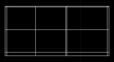
STEP 3:
- Enter L in command box
- Click on the lower left outside line corner
- Enter @-0.1,0 as next point
- Enter @0, -0.45 as next point
- Enter @-0.2,0 as next point
- Enter @0, -0.6 as next point
- Enter @0.86,0 as next point
- Enter @0,0.6 as next point
- Enter @0.2,0 as next point
- Enter @0,0.45 as next point
- Press ENTER
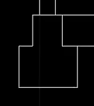
STEP 4:
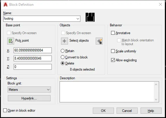
- Enter B in command box
- Enter Footing in NAME
- Pick the midpoint of the footing
- Select the footing
- Click delete
- Press OK
STEP 5:
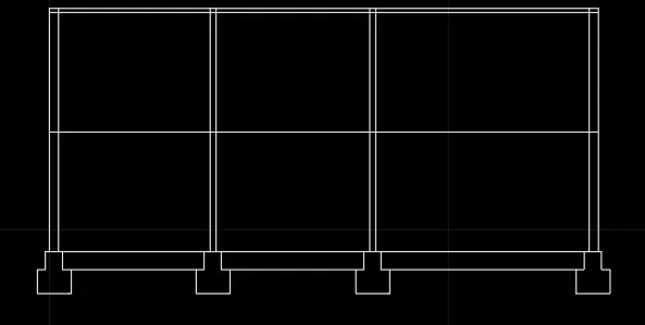
- Enter I in command box
- Enter footing in Name
- Press OK
- Place the footing in the required place
- Repeat the above step for 2 more times
STEP 6:
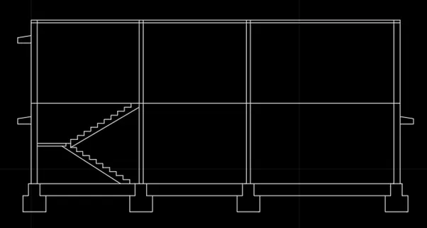
- Enter L in command box
- Track the inner wall
- Enter 1.40 as first point
- Press ENTER
- Enter O in command box
- Enter 0.1 as offset distance
- Place the line above 1.40m line
- Enter L in command box
- Close the landing
- Enter L in command box
- Switch off ORTHOMODE
- Place a slanting line at lower line of landing and connect it to the plinth
- Switch on OTHOMODE
- By tracking plinth line, enter 0.25 as first point
- Enter 0.15 as next point
- Repeat the above step till it reached landing
- Again, do the same step for building stairs above the landing
- Enter L in command box
- Click on the outer wall tracking the sunshade
- Enter 0.5 as next point
- Enter 0.2 as next point
- Switch off ORTHOMODE
- Connect it to the outer wall
- Enter CO in command box
- Copy the sunshade and place it at first floor
- Enter MI in command box
- Select the sunshade and create mirrored sunshade
- Enter Y in command box
- Enter M in command box
- Move the sunshade to the opposite side
STEP 7:
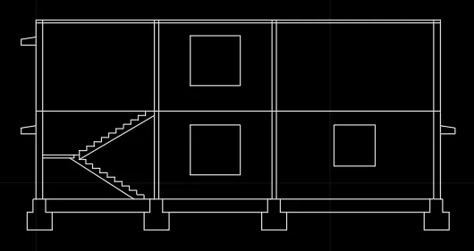
- Enter REC in command box
- Enter 1.07 as first corner
- Click dimensions
- Enter 1.7 as length
- Enter 1.7 as width
- Enter CO in command box
- Copy the window and place it at ground floor
- Enter REC in command box
- Enter 1.96 as first corner
- Click dimensions
- Enter 1.4 as length
- Enter 1.4 as width
- Place it at the centre
STEP 8:
- Delete the empty room
- Enter L in command box
- Create the roof tracking from first floor plan
- Enter H in command box
- Click ANSI31 hatch pattern with 0.05 scale factor
- Place the hatch on walls
- Enter H in command box
- Click AR-RSHKE pattern and enter 0.05 as scale factor
- Select the object and place the hatch
- Enter H in command box
- Click AR-CONC hatch pattern and enter 0.01 as scale factor
- Place it at plinth and roof slab
- Enter H in command box
- Click AR-CONC hatch pattern and enter 0.1 as scale factor
- Place it at sunshade and footing
- Click DIMENSIONS AND TEXT dropdown in LAYER.
- Enter DIML in command box and drag the dimensions.
- Enter DT in command box. Enter 0.2 as TEXT HEIGHT and 0 as TEXT ROTATION ANGE.
- Enter TEXT.
- Enter CO in command box. Copy the text and place it in another location.
- Enter TEXTEDIT in command box. Using this, editing in text can be done.
STEP 9:
- Click layer dropdown
- Select walls, stairs, sunshades, windows, roof slab, roof, plinth, footing, dimensions and text
- Click respected layers
- Apply the colours on the objects
RESULT:
The Section-AA is created by lines using AutoCAD. The step-by-step procedure for Section-AA is also explained. The Dimension is also entered in the diagram.
6)SECTION-BB
AIM: To create a section-BB using AutoCAD.
INTRODUCTI
ON: A section-BB using AutoCAD is created by Lines. The procedure and result should be written after creating a section-BB.
STEP 1:
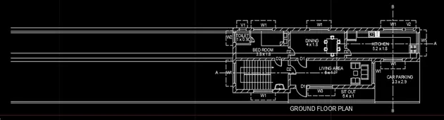
- Enter L in command box
- Extend the outer walls, inner walls and windows from the ground floor plan
- Extend every line point to same boundary
STEP 2:
- Enter L in command box
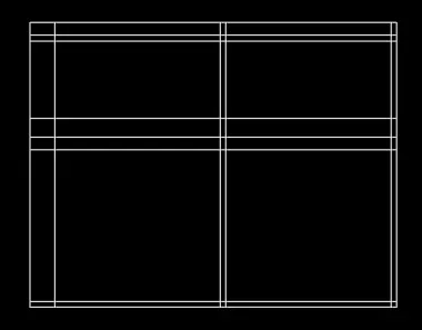
- Connect the left lines with a vertical line
- Enter O in command box
- Enter 0.45 as offset distance
- Select the left line and place it inwards
- Enter O in command box
- Enter 3 as offset distance
- Select the inner line and place it inwards
- Enter O in command box
- Enter 0.1 as offset distance
- Select the 3m line and place it inwards
- Enter O in command box
- Enter 3 as offset distance
- Select the 0.1m line and place it inwards
- Enter O in command box
- Enter 0.1 as offset distance
- Select the 3m line and place it inwards
- Enter TR in command box
- Delete all the extruded lines
STEP 3:
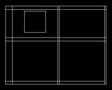
- Enter REC in command box
- Enter 0.80 as first corner point
- Click dimensions
- Enter 1.40 as length
- Enter 1.40 as width
- Place the square at the centre
STEP 4:
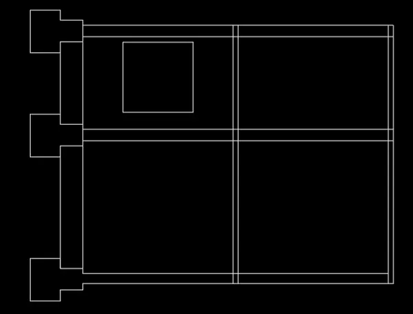
- Enter I in command box
- Enter footing in Name
- Enter 270 in angle
- Press OK
- Place the footing in correct place
- Repeat the same step for two more times
STEP 5:
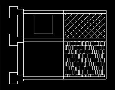
- Enter H in command box
- Click ANSI37 pattern and enter 0.1 as scale factor
- Select the object and place the hatch
- Enter H in command box
- Click AR-RSHKE pattern and enter 0.05 as scale factor
- Select the object and place the hatch
STEP 6:
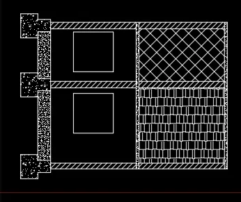
- Enter MATCHPROP in command box
- Select the walls, footing, plinth and roof slab from Section-AA
- Match those with Section-BB
STEP 7:
- Enter CO in command box
- Select the window
- Place it at below room
- Click DIMENSIONS AND TEXT dropdown in LAYER.
- Enter DIML in command box and drag the dimensions.
- Enter DT in command box. Enter 0.2 as TEXT HEIGHT and 0 as TEXT ROTATION ANGE.
- Enter TEXT.
- Enter CO in command box. Copy the text and place it in another location.
- Enter TEXTEDIT in command box. Using this, editing in text can be done.
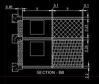
STEP 8:
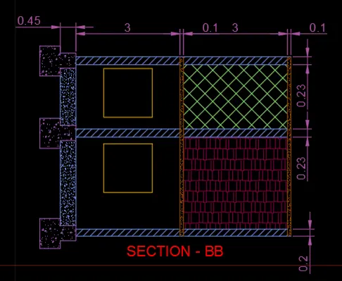
- Click layer dropdown
- Select walls, stairs, sunshades, windows, roof slab, roof, plinth, footing, dimensions and text
- Click respected layers
- Apply the colours on the objects
RESULT:
The Section-BB is created by lines using AutoCAD. The step-by-step procedure for Section-BB is also explained. The Dimension is also entered in the diagram.
STRUCTURAL LAYOUT
7)COLUMN LAYOUT
AIM: To create a column layout using AutoCAD.
INTRODUCTION: A column layout using AutoCAD is created by Lines. The procedure and result should be written after creating a column layout.
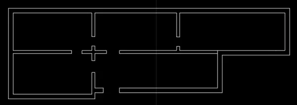
STEP 1:
- Enter CO in command box
- Copy it and place at different place
- Delete the hatch, dimensions, doors, windows, text and car parking area
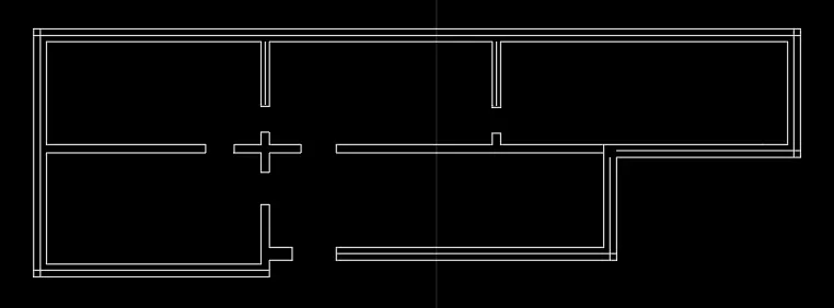
STEP 2:
- Enter L in command box
- Enter 0.12 as first point tracking the outer wall
- Connect the line to all the walls midpoint
- Enter F in command box
- Connect the lines with fillet command
STEP 3:
- Enter L in command box
- Enter 1 as first point tracking the outer wall
- Extend the line tracking the whole width of ground floor plan and enter 1 as next point
- Repeat the same step for other 3 sides
- Enter EXTEND in command box
- Extend all the lines within the created rectangular box
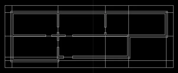
STEP 4:
- Enter TR in command box
- Delete all the lines except the extended lines
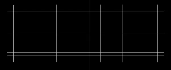
STEP 5:
- Enter REC in command box
- Click DIMENSIONS
- Enter 0.23 as length
- Enter 0.23 as width

STEP 6:
- Enter CO in command box
- Copy the square
- Switch on GEOMETRIC ORIGIN
- Click the origin of square and place it at all the connected lines
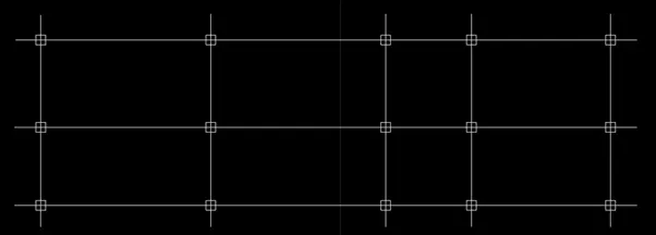
STEP 7:
- Enter TR in command box
- Delete the cross lines inside the square
- Select the squares and select red from the layers
- Press ENTER
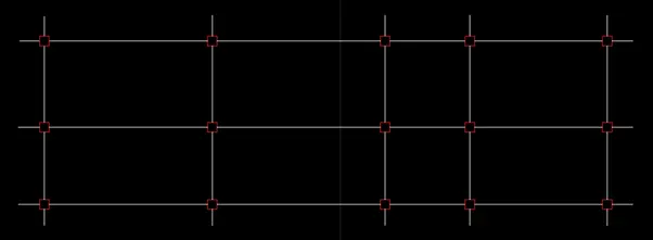
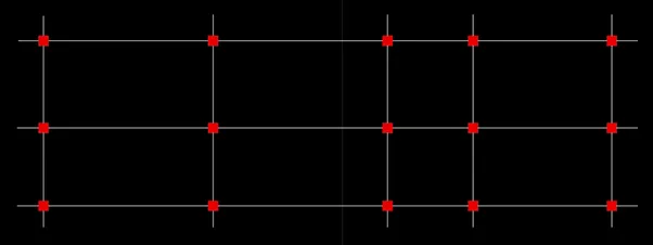
STEP 8:
- Enter H in command box
- Select the solid hatch pattern
- Place it in all squares
- Select red from the layers and change white into red
STEP 9:
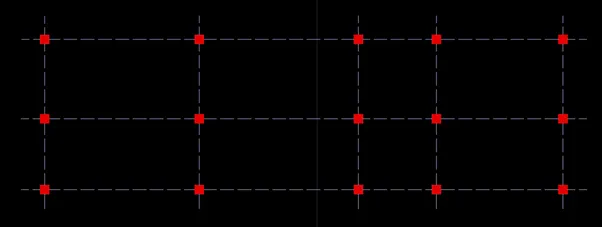
- Select all the lines
- Click the ISO dash from layers
- Click 152,152,204 colour from layers
- Apply those into the lines
STEP 10:
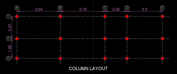
- Click DIMENSIONS AND TEXT dropdown in LAYER.
- Enter DIML in command box and drag the dimensions.
- Enter DT in command box. Enter 0.2 as TEXT HEIGHT and 0 as TEXT ROTATION ANGE.
- Enter TEXT.
- Enter CO in command box. Copy the text and place it in another location.
- Enter TEXTEDIT in command box. Using this, editing in text can be done.
RESULT:
The Column layout is created by lines using AutoCAD. The step-by-step procedure for Column layout is also explained. The Dimension is also entered in the diagram.
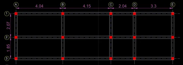
8)BEAM LAYOUT
AIM: To create a beam layout using AutoCAD.
INTRODUCTION: A beam layout using AutoCAD is created by Lines. The procedure and result should be written after creating a beam layout.
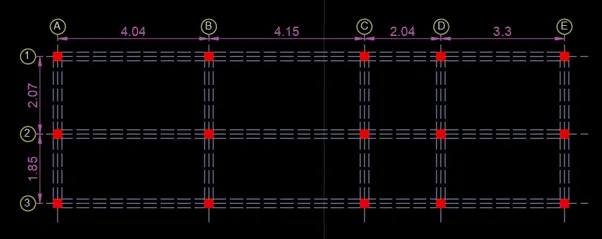
STEP 1:
- Enter CO in command box
- Copy the column layout drawing and place it at different place
- Enter O in command box
- Enter 0.12 as offset distance
- Click the lines and place offset line at either side
- Repeat same step for all the lines between columns
STEP 2:
- Select all the offset lines
- Click the 0 layer in layer dropdown
- Enter F in command box
- Select the corners of column
- Create corners
STEP 3:
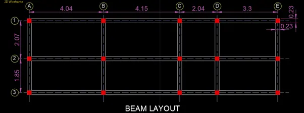
- Click DIMENSIONS AND TEXT dropdown in LAYER.
- Enter DIML in command box and drag the dimensions.
- Enter DT in command box. Enter 0.2 as TEXT HEIGHT and 0 as TEXT ROTATION ANGE.
- Enter TEXT.
- Enter CO in command box. Copy the text and place it in another location.
- Enter TEXTEDIT in command box. Using this, editing in text can be done.
RESULT:
The Beam layout is created by lines using AutoCAD. The step-by-step procedure for Beam layout is also explained. The Dimension is also entered in the diagram.
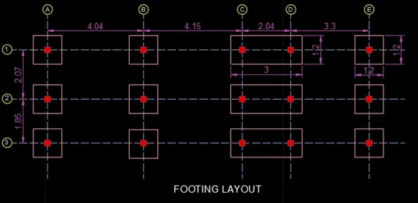
9)FOOTING LAYOUT
AIM: To create a footing layout using AutoCAD.
INTRODUCTION: A footing layout using AutoCAD is created by Lines. The procedure and result should be written after creating a footing layout
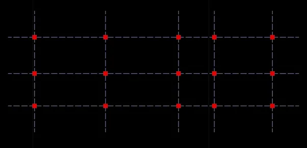
STEP 1:
- Enter CO in command box
- Copy the column layout
- Place it at different place
STEP 2:
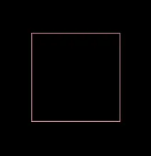
- Enter REC in command box
- Click DIMENSIONS
- Enter 1.20 as length
- Enter 1.20 as width
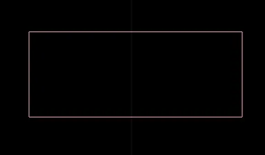
STEP 3:
- Enter REC in command box
- Click DIMENSIONS
- Enter 3 as length
- Enter 3 as width
STEP 4:
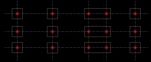
- Enter CO in command box
- Copy the square footing and place it at the columns which are far away
- Enter CO in command box
- Copy the rectangular footing and place it at the columns which are nearer
STEP 5:
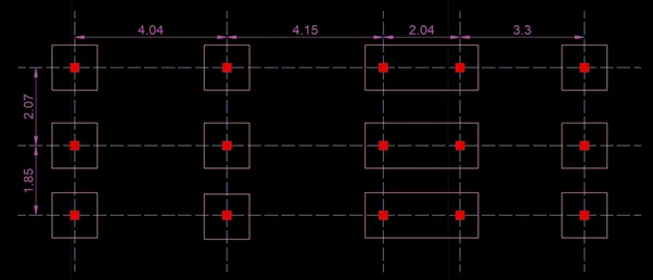
- Click DIMENSIONS AND TEXT dropdown in LAYER.
- Enter DIML in command box and drag the dimensions.
- Enter DT in command box. Enter 0.2 as TEXT HEIGHT and 0 as TEXT ROTATION ANGE.
- Enter TEXT.
- Enter CO in command box. Copy the text and place it in another location.
- Enter TEXTEDIT in command box. Using this, editing in text can be done.
RESULT:
The Beam layout is created by lines using AutoCAD. The step-by-step procedure for Beam layout is also explained. The Dimension is also entered in the diagram.
ARCHITECTURAL AND STRUCTURAL DRAWINGS