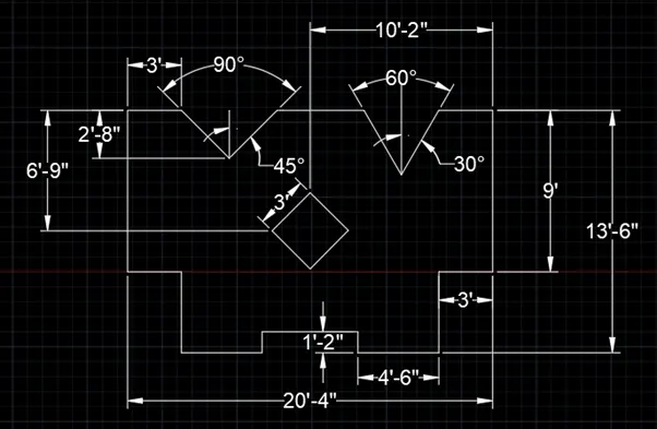
Drafting of various geometries using Chamfer, Fillet tool in AutoCad
1) DECIMAL
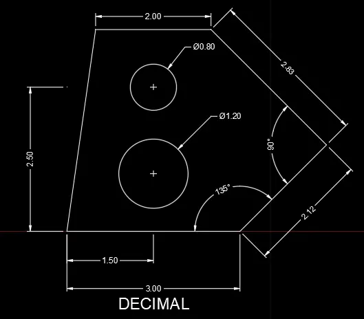
AIM: To create the diagram with the help of decimal units using AutoCAD.
INTRODUCTION: The diagram with the help of decimal units using AutoCAD is created by Lines and Circles. The procedure and result should be written after creating the diagram with the help of decimal units.
PROCEDURE:
STEP 1:
- Open the AutoCAD software and click start Drawing tab.
- Enter UNITS in command box.
- Select DECIMAL in TYPE, 0.00 in PRECISION and METERS in UNITS TO SCALE INSERTED CONTENT. Press OK.
- Switch on ORTHOMODE.
- Enter L in command box.
- Enter 0,0 as next point in command box.
- Enter @3.00<0 as next point in command box.
- Switch off ORTHOMODE.
- Enter @2.12<45 as next point in command box.
- Enter @2.83<135 as next point in command box.
- Switch on ORTHOMODE.
- Enter @-2.00,0.
- Press ENTER or click on CLOSE in the command box.

STEP 2:
- Click Circle, Diameter in the Circle dropdown in ribbon.
- Enter 1.50,1.00 as centre of the circle.
- Enter 1.20 as diameter of the circle.
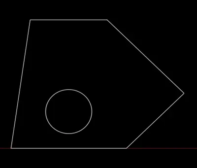
STEP 3:
- Click Circle, Diameter in the Circle dropdown in ribbon.
- Enter 1.50,1.00 as centre of the circle.
- Enter 1.20 as diameter of the circle.
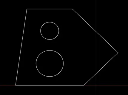
STEP 4:
- Enter DIMS in the command box.
- Click Modify.
- Click SYMBOLS AND ARROWS. Enter 0.01 in Arrow size.
- Click TEXT. Enter 0.01 in Text height.
- Click OK.
- Select STANDARD in Style. Click SET CURRENT. Click close.
- Enter DIM in command box.
- Click the first point and second point of the object. Drag it to the desired location. The dimension will be fixed in the preferred location in the workspace.
- Drag the dimension of all the objects in the workspace which are located in the given diagram.
- Enter TEXT in command box.
- Enter 0.2 as text height.
- Enter 0 as text rotation angle in command box.
- Press ENTER.
- Enter the text given in the diagram in the workspace.
- Press ENTER.
RESULT:
The diagram with the help of decimal units using AutoCAD is created by Lines and Circles using AutoCAD. The step-by-step procedure for creating diagram with decimal units is also explained. The Dimension and heading are also entered in the diagram.
2) ARCHITECTURAL
AIM: To create the diagram with architectural units using AutoCAD.
INTRODUCTION: The diagram with architectural units using AutoCAD is created by Lines. The procedure and result should be written after creating the diagram with architectural units.
PROCEDURE:
STEP 1:
- Open the AutoCAD software and click start Drawing tab.
- Enter UNITS in command box.
- Select ARCHITECTURAL in TYPE, 0’- 0” in PRECISION and INCHES in UNITS TO SCALE INSERTED CONTENT. Press OK.
- Switch on orthomode.
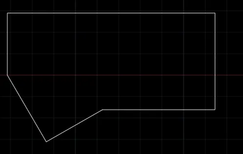
- Enter L in command box.
- Enter 0,0 as first point in the command box.
- Enter @0’0”,2’5” as next point in the command box.
- Enter @8’0”,0’0” as next point in the command box.
- Turn off ORTHOMODE.
- Enter @3’0” <300 as next point in the command box.
- Enter @2’6” <30 as next point in the command box.
- Connect the unconnected lines.
- Press ENTER or Click CLOSE
STEP 2:
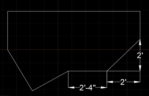
- Find the chamfer distance 1 and chamfer distance 2.
- Enter CHA in command box.
- Click Angle in command box.
- Enter 2’4” as chamfer length on first line.
- Enter 135 as chamfer angle from first line.
- Select the first line
- Click D on second line in command box.
- Enter 2’ as chamfer distance on first line.
- Enter 2’ as chamfer distance on second line.
- Click the second line.
- Click the cursor on the workspace.
STEP 3:
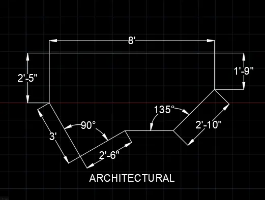
- Enter DIMS in the command box.
- Click Modify.
- Click SYMBOLS AND ARROWS. Enter 0’- 4 ¼”in Arrow size.
- Click TEXT. Enter 0’- 4 ¼” in Text height.
- Click PRIMARY UNITS. Select ARCHITECTURE and 0’0”.
- Click OK.
- Select STANDARD in Style. Click SET CURRENT. Click close.
- Enter DIMLIN in command box.
- Enter DIMALI for inclined objects and DIMANG for getting angles.
- Click the first point and second point of the object. Drag it to the desired location. The dimension will be fixed in the preferred location in the workspace.
- Drag the dimension of all the objects in the workspace which are located in the given diagram.
- Enter TEXT in command box.
- Enter 0’- 4.25” as text height.
- Enter 0 as text rotation angle in command box.
- Press ENTER.
- Enter the text given in the diagram in the workspace.
- Press ENTER.
RESULT:
- The diagram with the help of architectural units using AutoCAD is created by Lines using AutoCAD. The step-by-step procedure for creating diagram with architectural units is also explained. The Dimension and heading are also entered in the diagram.
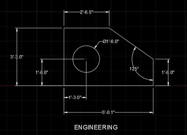
3) ENGINEERING
AIM: To create the diagram with Engineering units using AutoCAD.
INTRODUCTION: The diagram with Engineering units using AutoCAD is created by Lines. The procedure and result should be written after creating the diagram with Engineering units.
PROCEDURE:
STEP 1:
- Open the AutoCAD software and click start Drawing tab.
- Enter UNITS in command box.
- Select ENGINEERING in TYPE, 0’- 0.0” in PRECISION and INCHES in UNITS TO SCALE INSERTED CONTENT. Press OK.
- Switch on orthomode.
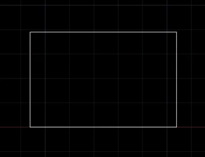
- Enter L in command box.
- Enter @ 5’0.1”,0’0.0” in command box.
- Enter @ 0’0.0”,3’3.0” in command box.
- Enter @ -5’0.1”,0’0.0” in command box.
- Enter @ 0’0.0”, - 3’3.0” in command box.
- Press ENTER or click CLOSE.
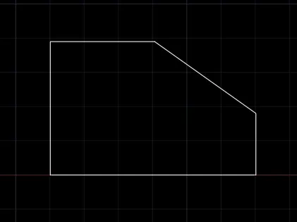
STEP 2:
- Enter CHA in command box.
- Click Angle and Enter 1’6.0” as chamfer length for first line.
- Enter 125 as angle.
- Select the line and click distance.
- Enter 1’9.0” as first chamfer distance and 2’5.6” as second chamfer distance.
- Select upper line as second line.
STEP 3:
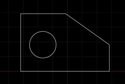
- Click Circle, Diameter in ribbon.
- Enter 1’3.0”,1’6.0” as centre point.
- Click diameter and enter 1’6.0” as diameter of circle.
STEP 4:
- Enter DIMS in the command box.
- Click Modify.
- Click SYMBOLS AND ARROWS. Enter 0’-2.18” in Arrow size.
- Click TEXT. Enter 0’-2.18” in Text height.
- Click OK.
- Click PRIMARY UNITS. Select ARCHITECTURE and 0’0.0”.
- Click OK.
- Select STANDARD in Style. Click SET CURRENT. Click close.
- Enter DIMLIN in command box.
- Enter DIMALI and DIMDIA in command box.
- Click the first point and second point of the object. Drag it to the desired location. The dimension will be fixed in the preferred location in the workspace.
- Drag the dimension of all the objects in the workspace which are located in the given diagram.
- Enter DT in command box.
- Enter 0’3.0” as text height.
- Enter 0 as text rotation angle in command box.
- Press ENTER.
- Enter the text given in the diagram in the workspace.
- Press ENTER.
RESULT:
- The diagram with the help of Engineering units using AutoCAD is created by Lines using AutoCAD. The step-by-step procedure for creating diagram with engineering units is also explained. The Dimension and heading are also entered in the diagram.
4) GEOMETRY 4
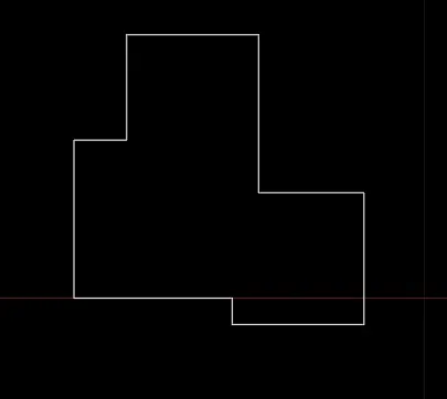
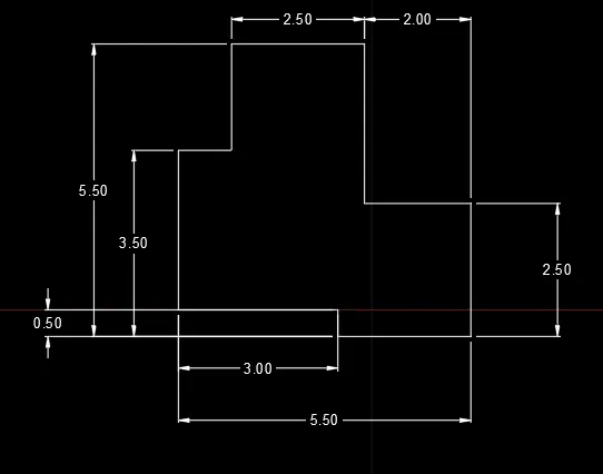
AIM: To create the Geometry 4 using AutoCAD.
INTRODUCTION: The geometry 4 units using AutoCAD is created by Lines. The procedure and result should be written after creating the diagram with Engineering units.
PROCEDURE:
STEP 1:
- Open the AutoCAD software and click start Drawing tab.
- Enter UNITS in command box.
- Select DECIMAL in TYPE, 0.00 in PRECISION and METERS in UNITS TO SCALE INSERTED CONTENT. Press OK.
- Switch on orthomode.
- Enter L in command box.
- Enter @3.00,0.00 as next point in command box.
- Enter @0.00, -0.50 as next point in command box.
- Enter @2.50,0.00 as next point in command box.
- Enter @0.00,2.50 as next point in command box.
- Enter @-2.00,0.00 as next point in command box.
- Enter @0.00,3.00 as next point in command box.
- Enter @-2.50,0.00 as next point in command box.
- Enter @0.00, -2.00 as next point in command box.
- Enter @-1.00,0.00 as next point in command box.
- Enter @0.00, -3.00 as next point in command box.
- Press ENTER or Click CLOSE.
STEP 2:
- Enter DIMS in the command box.
- Click Modify.
- Click SYMBOLS AND ARROWS. Enter 0.20in Arrow size.
- Click TEXT. Enter 0.20 in Text height.
- Click PRIMARY UNITS. Select DECIMAL and 0.00.
- Click OK.
- Select STANDARD in Style. Click SET CURRENT. Click close.
- Enter DIMLIN in command box.
- Click the first point and second point of the object. Drag it to the desired location. The dimension will be fixed in the preferred location in the workspace.
- Drag the dimension of all the objects in the workspace which are located in the given diagram.
- Enter TEXT in command box.
- Enter 0.20 as text height.
- Enter 0 as text rotation angle in command box.
- Press ENTER.
- Enter the text given in the diagram in the workspace.
- Press ENTER.
RESULT:
The Geometry 4 using AutoCAD is created by Lines using AutoCAD. The step-by-step procedure for creating geometry 4 is also explained. The Dimension and heading are also entered in the diagram.
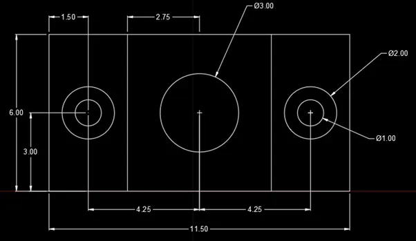
5) GEOMETRY 5
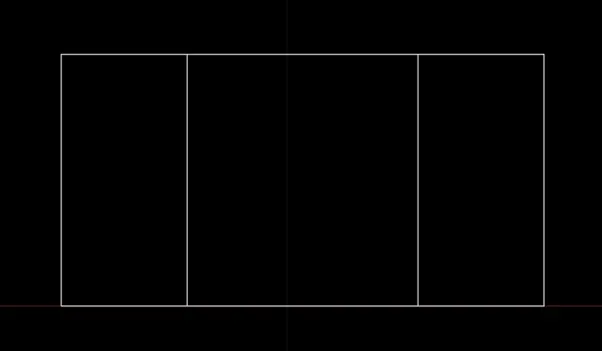
AIM: To create the Geometry 5 using AutoCAD.
INTRODUCTION: The geometry 5 units using AutoCAD is created by Lines and Circles. The procedure and result should be written after creating the Geometry 5.
PROCEDURE:
STEP 1:
- Open the AutoCAD software and click start Drawing tab.
- Enter UNITS in command box.
- Select DECIMAL in TYPE, 0.00 in PRECISION and METERS in UNITS TO SCALE INSERTED CONTENT. Press OK.
- Switch on orthomode.
- Enter L in command box.
- Enter 0,0 as first point.
- Enter @11.50,0.00 as next point.
- Enter @0.00,6.00 as next point.
- Enter @-11.50,0.00 as next point.
- Enter @0.00, -6.00 as next point.
- Press ENTER or Click CLOSE.

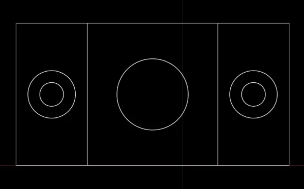
STEP 2:
- Enter O in command box.
- Enter 3.00 as offset distance.
- Select left line and drag it at 3.00 distance.
- Select right line and drag it at 3.00 distance.
- Press ENTER or Click EXIT.
STEP 3:
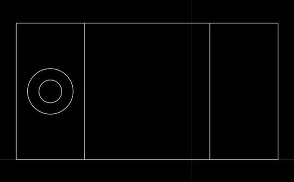
- Click Circle, Diameter in ribbon.
- Enter 1.50,3.00 as centre point for circle.
- Enter 2.00 as diameter of circle.
- Enter O and click layer.
- Click source and enter 0.50 as offset distance.
- Select the circle and click point inside the circle.
- Press ENTER or Click EXIT.
STEP 4:
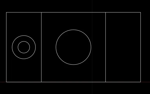
- Click Circle, Diameter in ribbon.
- Enter 5.75,3.00 as centre point for circle.
- Enter 3.00 as diameter of circle.
STEP 5:
- Click Circle, Diameter in ribbon.
- Enter 10.00,3.00 as centre point for circle.
- Enter 2.00 as diameter of circle.
- Enter O and click layer.
- Click source and enter 0.50 as offset distance.
- Select the circle and click point inside the circle.
- Press ENTER or Click EXIT.
STEP 6:
- Enter DIMS in the command box.
- Click Modify.
- Click SYMBOLS AND ARROWS. Enter 0.20 in Arrow size.
- Click TEXT. Enter 0.20 in Text height.
- Click PRIMARY UNITS. Select DECIMAL and 0.00.
- Click OK.
- Select STANDARD in Style. Click SET CURRENT. Click close.
- Enter DIMLIN in command box.
- Click the first point and second point of the object. Drag it to the desired location. The dimension will be fixed in the preferred location in the workspace.
- Drag the dimension of all the objects in the workspace which are located in the given diagram.
- Enter TEXT in command box.
- Enter 0.20 as text height.
- Enter 0 as text rotation angle in command box.
- Press ENTER.
- Enter the text given in the diagram in the workspace.
- Press ENTER.
RESULT:
The Geometry 5 using AutoCAD is created by Lines and Circles using AutoCAD. The step-by-step procedure for creating geometry 5 is also explained. The Dimension and heading are also entered in the diagram.
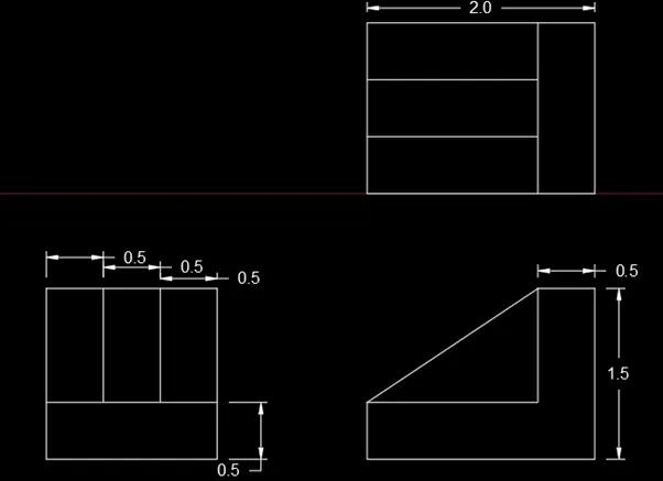
6) GEOMETRY 6
AIM: To create the Geometry 6 using AutoCAD.
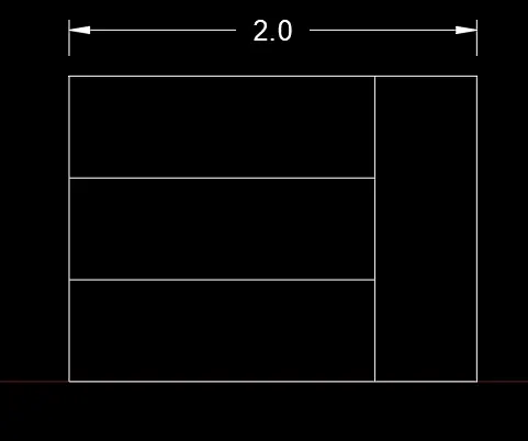
INTRODUCTION: The geometry 6 units using AutoCAD is created by Lines. The procedure and result should be written after creating the Geometry 6.
PROCEDURE:
STEP 1 OF DRAWING 1:
- Open the AutoCAD software and click start Drawing tab.
- Enter UNITS in command box.
- Select DECIMAL in TYPE, 0.0 in PRECISION and METERS in UNITS TO SCALE INSERTED CONTENT. Press OK.
- Switch on orthomode.
- Enter L in command box.
- Enter 0,0 as first point.
- Enter @2.0,0.0 as next point.
- Enter @0.0,1.5 as next point.
- Enter @-2.0,0.0 as next point.
- Enter @0.0, -1.5 as next point.
- Press ENTER or Click CLOSE.

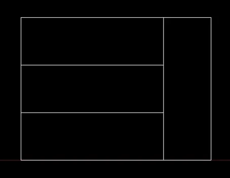
STEP 2 OF DRAWING 1:
- Enter O and 0.5 as offset distance.
- Select the line and drag it as 0.5 distance.
- Select the upper line and drag it at 0.5 distance.
- Press ENTER or click EXIT.

STEP 3 OF DRAWING 1:
- Enter TR and press ENTER.
- Click EDGE and EXTEND.
- Click the extruded lines
- Press ENTER.
STEP 4 OF DRAWING 1:
- Enter DS and go to MODIFY.
- Click PRIMARY UNITS and Select DECIMAL and 0.0
- Click SYMBOLS AND ARROWS. Enter 0.1 as ARROW SIZE.
- Click TEXT. Enter 0.1 as TEXT HEIGHT. Click OK.
- Click SET CURRENT and CLOSE.
- Enter DIMLIN
- Press ENTER.
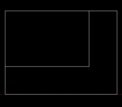
STEP 1 OF DRWAING 2:
- Enter L in command box.
- Enter 0,0 as first point.
- Enter @2.0,0.0 as next point.
- Enter @0.0,1.5 as next point.
- Enter @-1.5,0.0 as next point.
- Enter @0.0, -1.0 as next point.
- Enter @-1.5,0.0 as next point.
- Enter @1.5,0.0 as next point.
- Press ENTER or click CLOSE.
- Enter L
- Enter @0.0,1.0 as first point.
- Enter @1.5,0.0 as next point.
- Press ENTER or click CLOSE.
STEP 2 OF DRAWING 2:
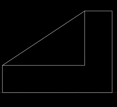
- Specify the two chamfer distance using DIMLIN.
- Enter CHA and click DISTANCE.
- Enter 1.5 as first chamfer distance.
- Enter 1.0 as second chamfer distance.
- Select the first line
- Select DISTANCE in second line.
- Enter 1.5 as first chamfer distance.
- Enter 1.0 as second chamfer distance.
- Select the second line
STEP 3 OF DRAWING 2:
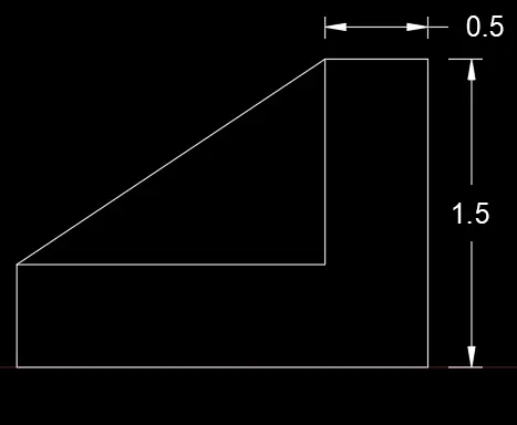
- Enter DIMLIN
- Press ENTER
STEP 1 OF DRAWING 3:
- Enter L in command box.
- Enter @0,0 as first point.
- Enter @1.5,0.0 as next point.
- Enter @0.0,1.5 as next point.
- Enter @-1.5,0.0 as next point.
- Enter @0.0, -1.5 as next point.
- Press ENTER or click CLOSE.

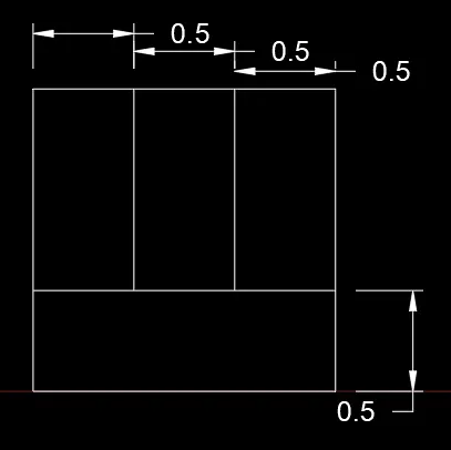
STEP 2 OF DRAWING 3:
- Enter O and 0.5 as offset distance.
- Select the lowest horizontal line and drag it at 0.5 distance.
- Select the vertical line and drag it at 0.5 distance two times.
- Press ENTER.

STEP 3 OF DRAWING 3:
- Enter TR in command box.
- Click EDGE and EXTEND.
- Select extruded lines
- Press ENTER.
- Enter DIMLIN and mention dimensions.
- Press ENTER
RESULT:
The Geometry 6 using AutoCAD is created by Lines using AutoCAD. The step-by-step procedure for creating geometry 6 is also explained. The Dimension and heading are also entered in the diagram.
7) GEOMETRY 7
AIM: To create the Geometry 7 using AutoCAD.
INTRODUCTION: The geometry 7 units using AutoCAD is created by Lines, Arcs, Circles and Rectangle. The procedure and result should be written after creating the Geometry 7.
PROCEDURE:
STEP 1:
- Open the AutoCAD software and click start Drawing tab.
- Enter UNITS in command box.
- Select DECIMAL in TYPE, 0 in PRECISION and METERS in UNITS TO SCALE INSERTED CONTENT. Press OK.
- Switch on orthomode.
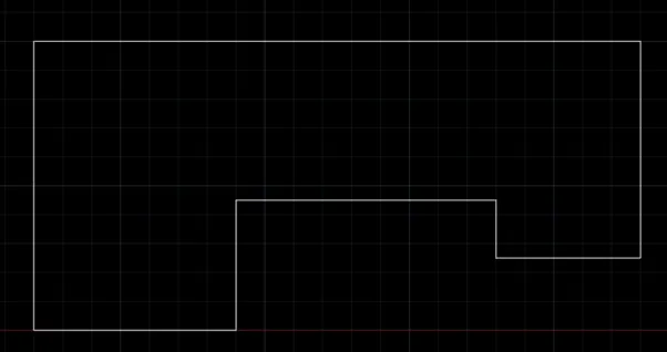
- Enter L in command box.
- Enter 0,0 as first point.
- Enter @70,0 as next point
- Enter @0,40 as next point
- Enter @90,0 as next point
- Enter @0, -15 as next point
- Enter @50,0 as next point
- Enter @0,75 as next point
- Enter @-210,0 as next point
- Enter @0, -100 as next point
- Press ENTER or CLOSE
STEP 2:
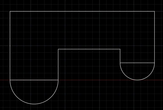
- Click START, END, RADIUS in RIBBON.
- Click start and end point.
- Enter 35 as radius.
- Click START, END, RADIUS in RIBBON.
- Click start and end point.
- Enter 25 as radius.
STEP 3:
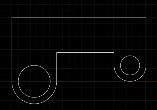
- Click Circle, Diameter in RIBBON.
- Enter 35,0 as centre
- Enter 50 as diameter
- Click Circle, Diameter in RIBBON.
- Enter 185,25 as centre
- Enter 30 as diameter
- Delete two unconnected lines
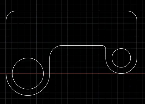
STEP 4:
- Enter F and select radius.
- Enter 20 as fillet radius.
- Select 1st object and 2nd object
- Enter F and select radius.
- Enter 6 as fillet radius.
- Select 1st object and 2nd object
- Enter F and select radius.
- Enter 15 as fillet radius.
- Select 1st object and 2nd object
STEP 5:
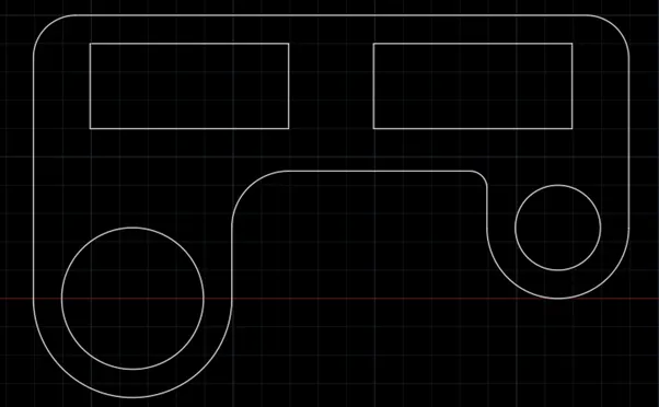
- Enter REC
- Enter 20,90 as first corner point.
- Click Dimension
- Enter 70 as length and 30 as width
- Enter 90,60 as another corner point
- Enter REC
- Enter 120,90 as first corner point.
- Click Dimension
- Enter 70 as length and 30 as width
- Enter 190,60 as another corner point
STEP 6:
- Enter DIMS in the command box.
- Click Modify.
- Click SYMBOLS AND ARROWS. Enter 5 in Arrow size.
- Click TEXT. Enter 5 in Text height.
- Click PRIMARY UNITS. Select DECIMAL and 0.
- Click OK.
- Select STANDARD in Style. Click SET CURRENT. Click close.
- Enter DIMLIN, DIMRAD and DIMDIA in command box.
- Click the first point and second point of the object. Drag it to the desired location. The dimension will be fixed in the preferred location in the workspace.
- Drag the dimension of all the objects in the workspace which are located in the given diagram.
- Press ENTER.
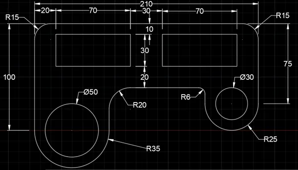
RESULT:
The Geometry 7 using AutoCAD is created by Lines, Arcs, Circles and Rectangle using AutoCAD. The step-by-step procedure for creating geometry 7 is also explained. The Dimension and heading are also entered in the diagram.
8) GEOMETRY 8
AIM: To create the Geometry 8 using AutoCAD.
INTRODUCTION: The geometry 8 units using AutoCAD is created by Lines and Circles. The procedure and result should be written after creating the Geometry 8.
PROCEDURE:
STEP 1:
- Open the AutoCAD software and click start Drawing tab.
- Enter UNITS in command box.
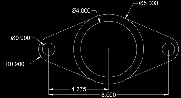
- Select DECIMAL in TYPE, 0.000 in PRECISION and METERS in UNITS TO SCALE INSERTED CONTENT. Press OK.
- Switch on orthomode.
- Click Centre, Diameter
- Enter 4.275,0 as centre
- Enter 5.00 as diameter
- Enter O
- Click LAYER and SOURCE
- Enter 0.5 as offset distance

STEP 2:
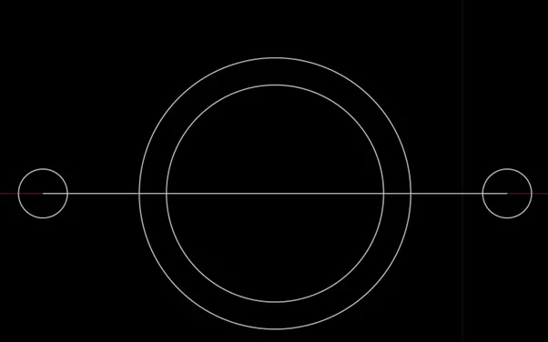
- Click Centre, Diameter
- Enter 0,0 as centre and 0.90 as diameter
- Click Centre, Diameter
- Enter 8.55,0 as centre and 0.90 as diameter
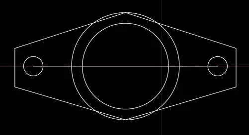
STEP 3:
- Enter L
- Click on the top point and turn off orthomode
- Place the line at 90 and switch on orthomode
- Enter 0.90 as next point
- Enter @0, -1,80 as next point
- Click on lowest line and again repeat the same step
STEP 4:
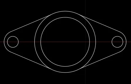
- Enter F and click radius
- Enter 0.90 as radius
- Select first and second object
- Repeat the same step in right side also
STEP 5:
- Enter DIMS in the command box.
- Click Modify.
- Click SYMBOLS AND ARROWS. Enter 0.300 in Arrow size.
- Click TEXT. Enter 0.300 in Text height.
- Click PRIMARY UNITS. Select DECIMAL and 0.000.
- Click OK.
- Select STANDARD in Style. Click SET CURRENT. Click close.
- Enter DIMLIN, DIMRAD and DIMDIA in command box.
- Click the first point and second point of the object. Drag it to the desired location. The dimension will be fixed in the preferred location in the workspace.
- Drag the dimension of all the objects in the workspace which are located in the given diagram.
- Press ENTER.
RESULT:
The Geometry 8 using AutoCAD is created by Lines and Circles using AutoCAD. The step-by-step procedure for creating geometry 8 is also explained. The Dimension and heading are also entered in the diagram.
9) GEOMETRY 9
AIM: To create the Geometry 9 using AutoCAD.
INTRODUCTION: The geometry 9 units using AutoCAD is created by Lines and Circles. The procedure and result should be written after creating the Geometry 9.
PROCEDURE:
STEP 1:
- Open the AutoCAD software and click start Drawing tab.
- Enter UNITS in command box.
- Select ARCHITECTURAL in TYPE, 0’0” in PRECISION and INCHES in UNITS TO SCALE INSERTED CONTENT. Press OK.
- Switch on orthomode.
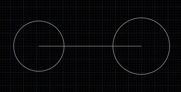
- Enter L
- Enter 0,0 as first point
- Enter @32’6”,0’0” as next point
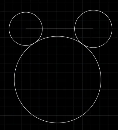
- Click Centre, Radius
- Enter 0,0 as centre
- Enter 8’ as radius
- Click Centre, Radius
- Enter 32’8”,0 as centre
- Enter 9’ as radius
STEP 2:
- Click TAN, TAN, RADIUS
- Click two tangents
- Enter 20’10” as radius
STEP 3:
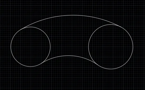
- Enter TR. Click EDGE and EXTEND.
- Click TAN, TAN, RADIUS
- Click two tangents
- Enter 41’8” as radius

STEP 4:
- Enter TR and click CROSSING
- Delete the centre line
STEP 5:
- Enter TR. Click EDGE AND EXTEND
- Enter DIMS in the command box.
- Click Modify.
- Click SYMBOLS AND ARROWS. Enter 10” in Arrow size.
- Click TEXT. Enter 10” in Text height.
- Click PRIMARY UNITS. Select ARCHITECTURAL and 0’0”.
- Click OK.
- Select STANDARD in Style. Click SET CURRENT. Click close.
- Enter DIMLIN, DIMRAD in command box.
- Click the first point and second point of the object. Drag it to the desired location. The dimension will be fixed in the preferred location in the workspace.
- Drag the dimension of all the objects in the workspace which are located in the given diagram.
- Press ENTER.
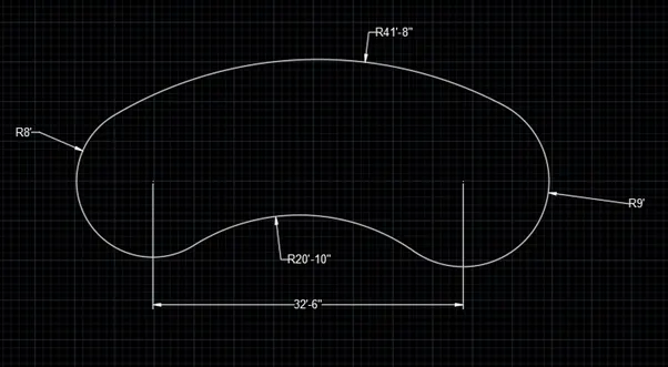
RESULT:
The Geometry 9 using AutoCAD is created by Lines and Circles using AutoCAD. The step-by-step procedure for creating geometry 9 is also explained. The Dimension and heading are also entered in the diagram.
10) GEOMETRY 10
AIM: To create the Geometry 10 using AutoCAD.
INTRODUCTION: The geometry 10 units using AutoCAD is created by Lines. The procedure and result should be written after creating the Geometry 10.
PROCEDURE:
STEP 1:
- Open the AutoCAD software and click start Drawing tab.
- Enter UNITS in command box.
- Select DECIMAL in TYPE, 0 in PRECISION and METERS in UNITS TO SCALE INSERTED CONTENT. Press OK.
- Switch on orthomode.
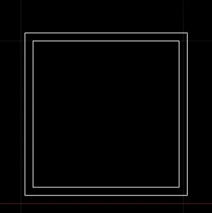
- Enter L as enter 0,0 as first point
- Enter @10,0 as next point
- Enter @0,10 as next point
- Enter @-10,0 as next point
- Enter @0,-10 as next point
- Press ENTER or CLOSE
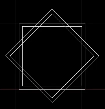
- Enter O
- Enter 0.5 as offset distance
- Press ENTER
- Enter TR
- Click EDGE AND EXTEND
- Press ENTER
STEP 2:
- Enter CO and select the object
- Click base point and place it
- Enter RO
- Select the object
- Enter 45
- Enter M and select the object
- Click the base point and switch off ortho
- Place the copied object at 5, -2 point
STEP 3:
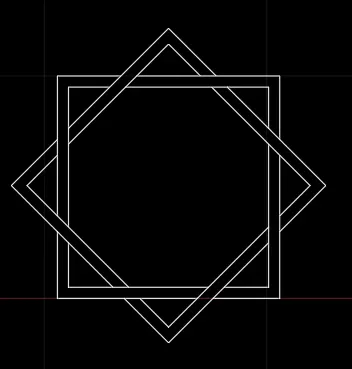
- Enter TR
- Click EDGE AND EXTEND
- Press ENTER or EXIT
RESULT:
The Geometry 10 using AutoCAD is created by Lines using AutoCAD. The step-by-step procedure for creating geometry 10 is also explained. The Dimension and heading are also entered in the diagram.
11) GEOMETRY 11
AIM: To create the Geometry 11 using AutoCAD.
INTRODUCTION: The geometry 11 units using AutoCAD is created by Lines. The procedure and result should be written after creating the Geometry 11.
PROCEDURE:
STEP 1:
- Open the AutoCAD software and click start Drawing tab.
- Enter UNITS in command box.
- Select ARCHITECTURAL in TYPE, 0’- 0” in PRECISION and INCHES in UNITS TO SCALE INSERTED CONTENT. Press OK.
- Switch on orthomode.
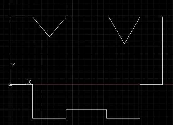
- Enter L
- Enter 0,0 as first point
- Enter @3’,0 as next point
- Enter @0, -4’6” as next point
- Enter @4’6”,0 as next point
- Enter @0,1’2” as next point
- Enter @5’4”,0 as next point
- Enter @0,1’2”as next point
- Enter @4’6”,0 as next point
- Enter @0,4’6” as next point
- Enter @3’,0 as next point
- Enter @0,9’ as next point
- Enter @-3’,0 as next point
- Enter 2’,4” tracking the upper line
- Enter @0, -3’7” as next point
- Switch off ORTHOMODE
- Click on upper 3’ line and connect it to the line of 3’7” vertical line lower point
- Enter MI which is mirror
- Click the lowest line as base point and click on opposite side
- Switch on ORTHOMODE
- Enter @-4’10”,0 as first point
- Enter 2’8” tracking the line
- Enter @0, -2’8” as next point. Press ENTER
- Click on upper 4’10” line and connect it to the line of 2’8” vertical line lower point
- Enter MI which is mirror
- Click the lowest line as base point and click on opposite side
- Switch on ORTHOMODE
- Enter @-3’,0 as next point
- Enter @0, -9’ as next point
- Press ENTER or Click CLOSE
STEP 2:
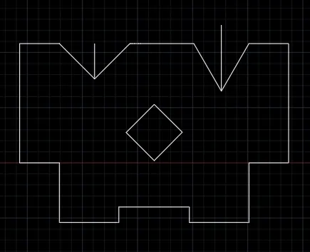
- Enter L in command box
- Enter 0,0 as first point
- Enter @3’,0 as next point
- Enter @0,3’ as next point
- Enter @-3’,0 as next point
- Enter @0, -3’ as next point
- Enter RO in command box
- Select the object and Enter 45
- Enter M in command box
- Select the object and click the base point
- Enter @10’2”,8’10” as next point
- Press ENTER
STEP 3:
- Enter DIMS in the command box.
- Click Modify.
- Click SYMBOLS AND ARROWS. Enter 10” in Arrow size.
- Click TEXT. Enter 10” in Text height.
- Click PRIMARY UNITS. Select ARCHITECTURAL and 0’0”.
- Click OK.
- Select STANDARD in Style. Click SET CURRENT. Click close.
- Enter DIMLIN, DIMANG and DIMALI in command box.
- Click the first point and second point of the object. Drag it to the desired location. The dimension will be fixed in the preferred location in the workspace.
- Drag the dimension of all the objects in the workspace which are located in the given diagram.
- Press ENTER.
RESULT:
The Geometry 11 using AutoCAD is created by Lines using AutoCAD. The step-by-step procedure for creating geometry 11 is also explained. The Dimension and heading are also entered in the diagram.