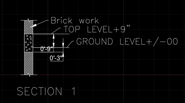
Creation of Column Schedule and Drawing Template using AutoCad
1)COLUMN SCHEDULE
AIM: To create the column schedule using AutoCAD.
INTRODUCTION: The column schedule using AutoCAD is created by Lines and Circles. The procedure and result should be written after creating the column schedule.
PROCEDURE:
STEP 1:
- Open the AutoCAD software and click start Drawing tab.
- Enter UNITS in command box.
- Select ENGINEERING in TYPE, 0’0” in PRECISION and INCHES in UNITS TO SCALE INSERTED CONTENT. Press OK.
- Switch on ORTHOMODE.
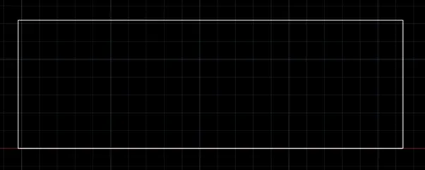
- Enter L and type 0,0 in command box.
- Type 60’,0’ in command box.
- Type 0’,20’ in command box.
- Type @-60’,0’ in command box.
- Type @0, -20’ in command box.
STEP 2:
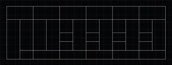
- Enter O in command box.
- Type 5’ as offset distance and select the upper line and drag it downwards.
- Enter O in command box.
- Type 3’ as offset distance and select the lower line and drag it upwards.
- Enter O in command box and type 10’ as offset distance. Select the left line and drag inwards.
- Repeat this step for four more times.
- Enter O in command box and type 5’ as offset distance. Select the left line and drag inwards.
- Repeat this step for five more times.
- Enter O in command box and type 5’ as offset distance. Select the 5’ offset line and drag downwards.
- Enter O in command box and type 3’6” as offset distance. Select the 5’ offset line and drag downwards.
- Repeat this step one more time.
- Enter TR in command box.
- Delete all the unwanted lines.
STEP 3:
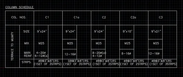
- Enter ST in command box.
- Select romans.shx in FONT NAME and HEIGHT as 8”. Click OK.
- Click ANNOTATION tab and Select SINGLE LINE in RIBBON.
- Enter the text height as 8” and rotation angle as 0.
- For TERRACE TO MUMTY, enter rotation angle as 90.
- Select MULTILINE TEXT in RIBBON.
- Click SYMBOL and select others.
- Click ARIAL as font and select Latin Small Letter Alpha (U+0251).
- Select it and press ENTER.
- Enter CO in command box and copy it in the required place.
- Select MULTILINE TEXT in RIBBON.
- Click SYMBOL and select others.
- Click ARIAL as font and select Latin Small Letter O with Stroke (U+00F8).
- Select it and press ENTER.
- Enter CO in command box and copy it in the required place.
- Enter TEXTEDIT in command box to edit the text.
- Enter M in command box to move the text and diagram.
STEP 4:
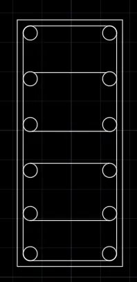
- Enter REC in command box.
- Click the first corner point in C1 column.
- Click DIMENSIONS in command box.
- Enter 9” as length and 24” as width.
- Enter O in command box.
- Enter 1” as offset distance.
- Click the rectangle and drag it inside.
- Enter C in command box and type 1” as radius.
- Enter CO in command box.
- Copy the circle and place it in the corners.
- Enter CO in command box.
- Copy the circle and place it at the distance of 6” and 5”.
- Place 5 circles in the single column of rectangle.
- Enter L and Click at the two circles down side.
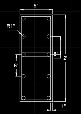
- Enter O in command box.
- Type 3.5”, 1” and 4.8” as offset distance and Place it in the appropriate position.
- Enter F in command box.
- Select the corners and make the curve.
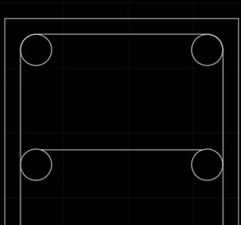
- Enter F in command box.
- Select line and circle to make the curve.
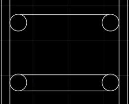
- Enter CO in command box.
- Select the Latin Small Letter Alpha (U+0251) and place it in the outside of rectangle.
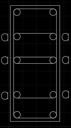
STEP 5:
- Enter REC in command box.
- Click the first corner point in C1a column.
- Click DIMENSIONS in command box.
- Enter 9” as length and 24” as width.
- Enter O in command box.
- Enter 1” as offset distance.
- Click the rectangle and drag it inside.
- Enter C in command box and type 1” as radius.
- Enter CO in command box.
- Copy the circle and place it in the corners.
- Enter CO in command box.
- Enter CO in command box.
- Copy the circles at the distance of 2.5”.
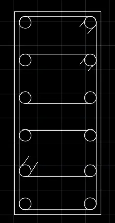
- Place 6 circles at one column.
- Enter L in command box.
- Click at the two circles down side.
- Enter O in command box.
- Enter 4.5”,3” and 4.8” as offset distance and place all at the appropriate place.
- Switch off ORTHOMODE.
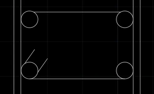
- Enter L and click the nearest point in circle.
- Type 3” as length of line.
- Enter O and type 3” as offset distance and drag at the opposite side.
- Enter F in command box.
- Select the corner to make the curve and give 1” as fillet radius.
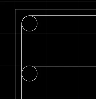
- Enter F in command box.
- Select the line and circle to make a curve.
- Repeat the same step for other two bars at the top.
STEP 6:
- Enter REC in command box.
- Click the first corner point in C2 column.
- Click DIMENSIONS in command box.
- Enter 9” as length and 24” as width.
- Enter O in command box.
- Enter 1” as offset distance.
- Click the rectangle and drag it inside.
- Enter C in command box and type 1” as radius.
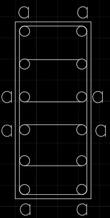
- Enter CO in command box.
- Copy the circle and place it in the corners.
- Enter CO in command box.
- Copy the circles at the distance of 2.5”.
- Place 6 circles at one column.
- Enter L in command box.
- Click at the two circles down side.
- Enter O in command box.
- Enter 4.5”,3” and 4.8” as offset distance and place all at the appropriate place.
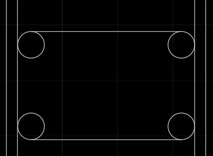
- Enter F in command box.
- Enter 1” as fillet radius.
- Select the corners of the rectangle.
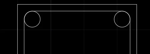
- Enter F in command box.
- Select the line and circle to make the curve.
- Enter CO in command box.
- Select the Latin Small Letter Alpha (U+0251) and place it in the outside of rectangle.
STEP 7:
- Enter REC in command box.
- Click the first corner point in C2a column.
- Click DIMENSIONS in command box.
- Enter 9” as length and 10” as width.
- Enter O in command box.
- Enter 1” as offset distance.
- Click the rectangle and drag it inside.
- Enter C in command box and type 1” as radius.
- Enter CO in command box.
- Copy the circle and place it in the corners.
- Enter CO and copy the circles at 3.5” distance.
- Place 3 circles in one column.
- Switch off ORTHOMODE.
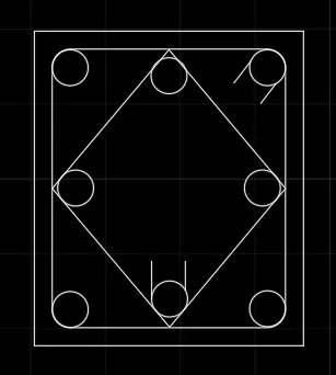
- Enter L and click at the midpoint of line.
- Connect the line as a diamond structure.
- Enter F in command box.
- Enter 1” as offset radius.
- Click the corners to make curve.

- Enter L and click the nearest point in circle.
- Type 3” as length of line.
- Enter O and type 3” as offset distance and drag at the opposite side.
STEP 8:
- Enter REC in command box.
- Click the first corner point in C3 column.
- Click DIMENSIONS in command box.
- Enter 9” as length and 24” as width.
- Enter O in command box.
- Enter 1” as offset distance.
- Click the rectangle and drag it inside.
- Enter C in command box and type 1” as radius.
- Enter CO in command box.
- Copy the circle and place it in the corners.
- Enter CO in command box.
- Copy the circles at the distance of 2.5”.
- Place 6 circles at one column.
- Enter L in command box.
- Click at the two circles down side.
- Enter O in command box.
- Enter 4.5”,3” and 4.8” as offset distance and place all at the appropriate place.
- Enter F in command box.
- Enter 1” as fillet radius.
- Select the corners of the rectangle.
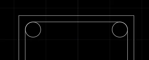
- Enter F in command box.
- Select the line and circle to make the curve.
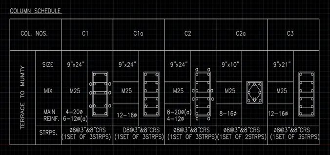
RESULT:
The Column schedule is created by lines using AutoCAD. The step-by-step procedure for creating the column schedule is also explained. The Dimension is also entered in the diagram.
2)WINDOW SCHEDULE
AIM: To create the window schedule using AutoCAD.
INTRODUCTION: The window schedule using AutoCAD is created by Lines. The procedure and result should be written after creating the window schedule
PROCEDURE:
STEP 1:
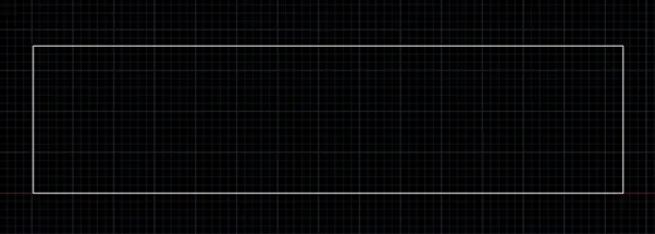
- Open the AutoCAD software and click start Drawing tab.
- Enter UNITS in command box.
- Select ENGINEERING in TYPE, 0’0” in PRECISION and INCHES in UNITS TO SCALE INSERTED CONTENT. Press OK.
- Switch on ORTHOMODE.
- Enter L in command box.
- Enter 60’,0’ as first point.
- Enter 0’,20’ as next point.
- Enter @-60’,0’ as next point.
- Enter @0’, -20’ as next point.
STEP 2:
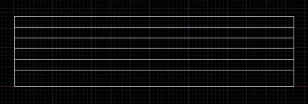
- Enter O in command box.
- Enter 2.3’ as offset distance.
- Select the upper horizontal line.
- Drag it downwards.
- Repeat the same step four more times.
STEP 3:
- Enter O in command box.
- Type 5’ as offset distance.
- Select the left line and drag inwards.
- Enter O in command box.
- Type 10’ as offset distance.
- Select the 5’ line and drag inwards.
- Enter O in command box.
- Type 15’ as offset distance.
- Select the 10’ line and drag inwards.
- Enter O in command box.
- Type 13’ as offset distance.
- Select the 15’ line and drag inwards.
- Enter O in command box.
- Type 17’ as offset distance.
- Select the 13’ line and drag inwards.
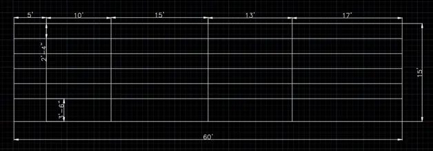
STEP 4:
- Enter ST in command box.
- Select romans.shx in FONT NAME and HEIGHT as 8”. Click OK.
- Click ANNOTATION tab and Select SINGLE LINE in RIBBON.
- Enter the text height as 8” and rotation angle as 0.
- Select MULTILINE TEXT in RIBBON.
- Enter the dimensions.
- Click Tab after entering 1/2, 1/4 and 3/4.
- Enter TEXTEDIT in command box to edit the text.
- Enter M in command box to move the text.
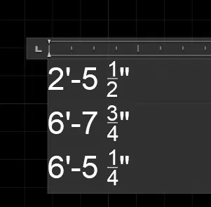
RESULT:
The Window schedule is created by lines using AutoCAD. The step-by-step procedure for creating the window schedule is also explained. The Dimension is also entered in the diagram.
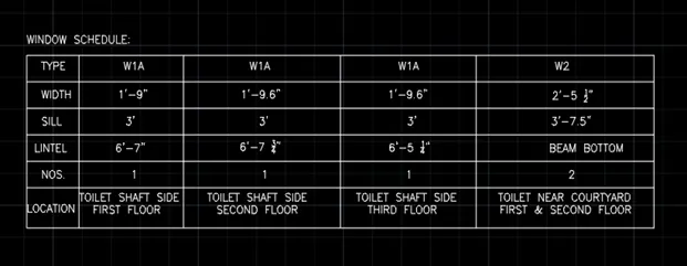
3)DRAWING TEMPLATE
AIM: To create the drawing template using AutoCAD.
INTRODUCTION: The drawing template using AutoCAD is created by Lines. The procedure and result should be written after creating the drawing template.
PROCEDURE:
STEP 1:
- Open the AutoCAD software and click start Drawing tab.
- Enter UNITS in command box.
- Select ENGINEERING in TYPE, 0’0” in PRECISION and INCHES in UNITS TO SCALE INSERTED CONTENT. Press OK.
- Switch on ORTHOMODE.
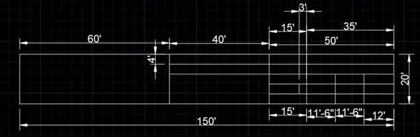
- Enter L and type 0,0 in command box.
- Enter 150’,0’ as first point.
- Enter 0’,20’ as next point.
- Enter @-150’,0’ as next point.
- Enter @0’, -20’ as next point.
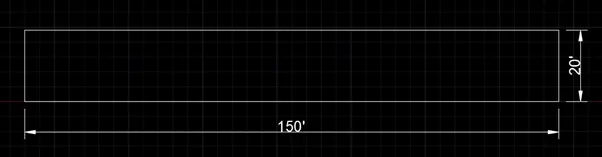
STEP 2:
- Enter O in command box.
- Enter 60’ as offset distance.
- Select the left line and drag it inwards.
- Enter O in command box.
- Enter 40’ as offset distance.
- Select the 60’ line and drag it inwards.
- Enter O in command box.
- Enter 50’ as offset distance.
- Select the 40’ line and drag it inwards.
- Enter O in command box.
- Enter 4’ as offset distance.
- Select the upper line and drag it inwards.
- Repeat the same step four more times.
- Enter O in command box.
- Enter 15’ as offset distance.
- Select the 40’ line and drag it inwards.
- Enter O in command box.
- Enter 11’6” as offset distance.
- Select the 15’ line and drag it inwards.
- Repeat the same step one more time.
- Enter O in command box.
- Enter 12’ as offset distance.
- Select the 11’6” line and drag it inwards.
- Enter O in command line.
- Enter 3’ as offset distance.
- Select the 15’ line and drag it left side.
STEP 3:
- Enter ST in command box.
- Select romans.shx in FONT NAME and HEIGHT as 8”. Click OK.
- Click ANNOTATION tab and Select SINGLE LINE in RIBBON.
- Enter the text height as 8” and rotation angle as 0.
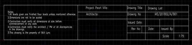
- Enter the text in the drawing template.
- Enter TEXTEDIT in command box to edit the text.
- Enter M in command box to move the text.
RESULT:
The Drawing template is created by lines using AutoCAD. The step-by-step procedure for creating the drawing template is also explained. The Dimension is also entered in the diagram.
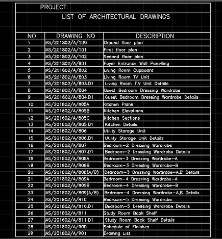
4)LIST OF DRAWING SCHEDULE
AIM: To create the list of drawing schedule using AutoCAD.
INTRODUCTION: The list of drawing schedule using AutoCAD is created by Lines. The procedure and result should be written after creating the list of drawing schedule.
PROCEDURE:
STEP 1:
- Open the AutoCAD software and click start Drawing tab.
- Enter UNITS in command box.
- Select ENGINEERING in TYPE, 0’0” in PRECISION and INCHES in UNITS TO SCALE INSERTED CONTENT. Press OK.
- Switch on ORTHOMODE.
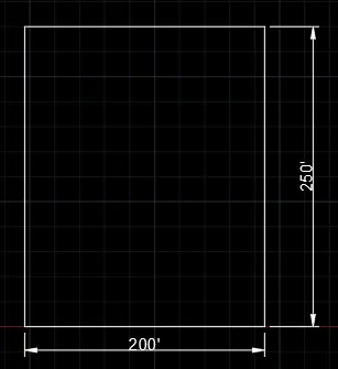
- Enter L and type 0,0 in command box.
- Type 200’,0’ in command box.
- Type 0’,250’ in command box.
- Type @-200’,0’ in command box.
- Type @0, -250’ in command box.
STEP 2:
- Enter O in command box.
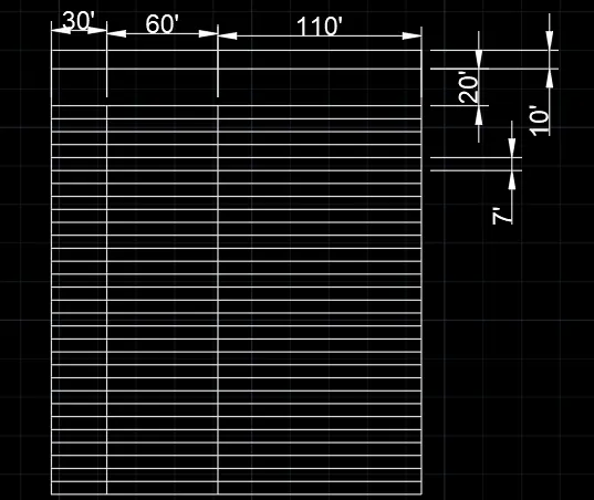
- Enter 30’ as offset distance.
- Select the left line and drag it inwards.
- Enter O in command box.
- Enter 60’ as offset distance.
- Select the 30’ line and drag it inwards.
- Enter O in command box.
- Enter 110’ as offset distance.
- Select the 60’ line and drag it inwards.
- Enter O in command box.
- Enter 10’ as offset distance.
- Select the upper line and drag it inwards.
- Enter O in command box.
- Enter 20’ as offset distance.
- Select the 10’ line and drag it inwards.
- Enter O in command box.
- Enter 7’ as offset distance.
- Select the 20’ line and drag it inwards.
- Repeat the same step for 29 times
STEP 3:
- Enter ST in command box.
- Select romans.shx in FONT NAME and HEIGHT as 8”. Click OK.
- Click ANNOTATION tab and Select SINGLE LINE in RIBBON.
- Enter the text height as 8” and rotation angle as 0.
- Enter the text in the drawing template.
- Enter CO in command box.
- Click ARRAY and enter 29.
- Select the text and press ENTER.
- Enter TEXTEDIT in command box to edit the text.
- Enter M in command box to move the text.
RESULT:
The List of Drawing schedule is created by lines using AutoCAD. The step-by-step procedure for creating the list of drawing schedule is also explained. The Dimension is also entered in the diagram.
5)BEAM DETAIL
AIM: To create the beam detail using AutoCAD.
INTRODUCTION: The beam detail using AutoCAD is created by Lines. The procedure and result should be written after creating the beam detail.
PROCEDURE:
STEP 1:
- Open the AutoCAD software and click start Drawing tab.
- Enter UNITS in command box.
- Select ENGINEERING in TYPE, 0’0” in PRECISION and INCHES in UNITS TO SCALE INSERTED CONTENT. Press OK.
- Switch on ORTHOMODE.
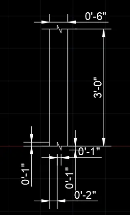
- Enter L and type 0,0 in command box.
- Type 6”,0” as first point in command box.
- Type @0”,1” as next point.
- Type @2”,0” as next point.
- Type @0”, -2” as next point.
- Type @6””,0” as next point.
- Switch off ORTHOMODE.
- Connect the upper and lower corner in the rectangle.
- Enter TR in command box.
- Delete the unwanted lines.
- Enter CO in the command box.
- Enter 3’ as distance and copy it.
- Enter L and enter 0,0.
- Enter @0’,3’ as next point.
- Enter O in command box.
- Enter 6” as offset distance.
- Select the left line and drag it right side.
STEP 2:
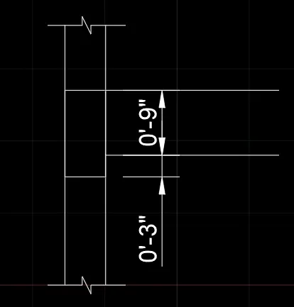
- Enter REC in command box.
- Enter 1.2” as first corner point.
- Click Dimensions.
- Enter 6” as length and 1’ as width.
- Extend the upper line of rectangle and enter 2’ as next point.
- Enter O in command box.
- Enter 9” as offset distance and select the 2’ line. Drag it downside.
- Enter DIMS in command box.
- Click MODIFY.
- Click LINE. Enter 2” in EXTEND BEYOND LINES and 5” in OFFSET FROM ORIGIN.
- Click SYMBOLS AND ARROWS. Enter 3” as ARROW SIZE.
- Click TEXT. Enter 3” as TEXT HEIGHT.
- Click PRIMARY UNITS.
- Enter ENGINEERING in UNIT FORMAT and 0’0” in PRECISION.
- Click SET CURRENT. Click CLOSE.
STEP 3:
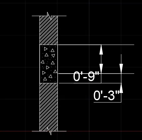
- Enter H in command box.
- Click the STEEL PATTERN in PATTERN panel in RIBBON.
- Select the upper and lower rectangle and hatch the pattern.
- Click H in command box.
- Click the AR-CONC PATTERN in PATTERN panel in RIBBON.
- Select the rectangle and hatch.
STEP 4:
- Enter DT in command box.
- Enter 5” as text height and 0 as rotation angle.
- Type the text.
- Enter MULTILEADER in command box.
- Click the object and type the text.
- Enter TEXTEDIT in command box to edit the text.
- Enter M in command box to move the text and diagram.
- Save the file.
RESULT:
The Beam detail is created by lines using AutoCAD. The step-by-step procedure for creating beam detail is also explained. The Dimension is also entered in the diagram.