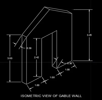
Creating a Floor plan, Footing detail and Isometric view using AutoCad
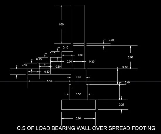
C1) C.S. OF LOAD BEARING WALL OVER SPREAD FOOTING
AIM: To create cross section of load bearing wall over spread footing using AutoCAD.
INTRODUCTION: The cross section of load bearing wall over spread footing using AutoCAD is created by Lines and Rectangles. The procedure and result should be written after creating the cross section of load bearing wall over spread footing.
PROCEDURE:
STEP 1:
- Open the AutoCAD software and click start Drawing tab.
- Enter UNITS in command box.
- Select DECIMAL in TYPE, 0.00 in PRECISION and METERS in UNITS TO SCALE INSERTED CONTENT. Press OK.
- Switch on ORTHOMODE.
- Enter REC in the command box.
- Enter first corner point as 0,0 in the command box.
- Click dimensions in the other corner point in the command box.
- Enter 0.90 in length for rectangles in the command box.
- Enter 0.25 in width for rectangles in the command box.
- Click the moving rectangle in the upper side on the workspace.
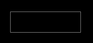
STEP 2:
- Enter REC in the command box.
- Enter first corner point as 0.20,0.25 in the command box.
- Click dimensions in the other corner point in the command box.
- Enter 0.50 in length for rectangles in the command box.
- Enter 0.40 in width for rectangles in the command box.
- Click the moving rectangle in the upper side on the workspace.
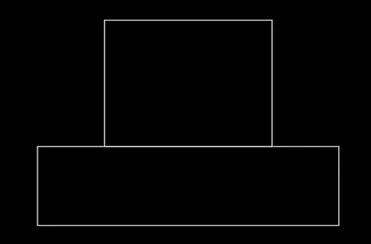
STEP 3:
- Enter REC in the command box.
- Enter first corner point as 0.25,0.65 in the command box.
- Click dimensions in the other corner point in the command box.
- Enter 0.40 in length for rectangles in the command box.
- Enter 0.40 in width for rectangles in the command box.
- Click the moving rectangle in the upper side on the workspace.
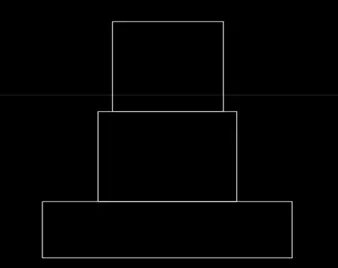
STEP 4:
- Enter REC in the command box.
- Enter first corner point as 0.30,1.05 in the command box.
- Click dimensions in the other corner point in the command box.
- Enter 0.30 in length for rectangles in the command box.
- Enter 0.60 in width for rectangles in the command box.
- Click the moving rectangle in the upper side on the workspace.
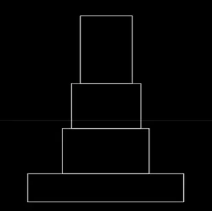
STEP 5:
- Enter REC in the command box.
- Enter first corner point as 0.30,1.65 in the command box.
- Click dimensions in the other corner point in the command box.
- Enter 0.30 in length for rectangles in the command box.
- Enter 0.05 in width for rectangles in the command box.
- Click the moving rectangle in the upper side on the workspace.
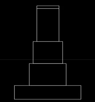
STEP 6:
- Enter REC in the command box.
- Enter first corner point as 0.30,1.70 in the command box.
- Click dimensions in the other corner point in the command box.
- Enter 0.30 in length for rectangles in the command box.
- Enter 1.00 in width for rectangles in the command box.
- Click the moving rectangle in the upper side on the workspace.
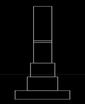
STEP 7:
- Enter REC in the command box.
- Enter first corner point as 0.25,1.05 in the command box.
- Click dimensions in the other corner point in the command box.
- Enter 1.15 in length for rectangles in the command box.
- Enter 0.15 in width for rectangles in the command box.
- Click the moving rectangle in the left side on the workspace.
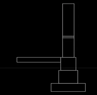
STEP 8:
- Enter L in the command box.
- Enter -0.60,1.05 in first point in the command box.
- Place the cursor upward and enter @0,0.15 in next point in the command box.
- Place the cursor right side and enter @0.30,0 in next point in the command box.
- Place the cursor upward and enter @0,0.15 in next point in the command box.
- Place the cursor right side and enter @0.30,0 in next point in the command box.
- Place the cursor upward and enter @0,0.15 in next point in the command box.
- Place the cursor right side and enter @0.30,0 in next point in the command box.
- Press ENTER or Click CLOSE in the command box.
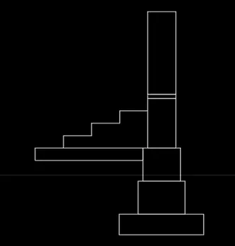
STEP 9:
- Enter TR in command box which is used to trim the objects.
- Press ENTER.
- Click EDGE in the command box.
- Click NO EXTEND in the command box.
- Select second triangle’s upper line.
- Press ENTER.
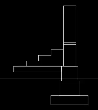
STEP 10:
- Enter DIMS in the command box.
- Click Modify.
- Click SYMBOLS AND ARROWS. Enter 0.05 in Arrow size.
- Click TEXT. Enter 0.05 in Text height.
- Click OK.
- Select STANDARD in Style. Click SET CURRENT. Click close.
- Enter DIM in command box.
- Click the first point and second point of the object. Drag it to the desired location. The dimension will be fixed in the preferred location in the workspace.
- Drag the dimension of all the objects in the workspace which are located in the given diagram.
- Enter TEXT in command box.
- Enter 0.1 as text height.
- Enter 0 as text rotation angle in command box.
- Press ENTER.
- Enter the text given in the diagram in the workspace.
- Press ENTER.
RESULT:
C.S of load bearing wall over spread footing is created by Lines and Rectangles using AutoCAD. The step-by-step procedure for creating cross section of load bearing wall over spread footing is also explained. The Dimension and heading are also entered in the diagram.
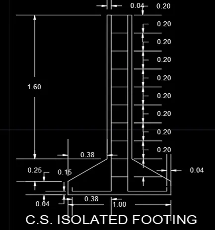
C2) C.S. ISOLATED FOOTING
AIM: To create cross section of isolated footing using AutoCAD.
INTRODUCTION: The cross section of isolated footing using AutoCAD is created by Lines. The procedure and result should be written after creating the cross section of isolated footing.
PROCEDURE:
STEP 1:
- Open the AutoCAD software and click start Drawing tab.
- Enter UNITS in command box.
- Select DECIMAL in TYPE, 0.00 in PRECISION and METERS in UNITS TO SCALE INSERTED CONTENT. Press OK.
- Switch on orthomode.
- Enter L in command box.
- Enter 0,0 as first point in the command box.
- Place the cursor right side and enter @1.00,0 as next point in the command box.
- Place the cursor upwards and enter @0,0.15 as next point in the command box.
- Switch off orthomode.
- Place the cursor left side and enter @-0.38,0.25 as next point in the command box.
- Switch on orthomode.
- Place the cursor upwards and enter @0,1.60 as next point in the command box.
- Place the cursor left side and enter @-0.24,0 as next point in the command box.
- Place the cursor downwards and enter @0, -1.60 as next point in the command box.
- Switch off orthomode.
- Place the cursor left side and enter @-0.38, -0.25 as next point in the command box.
- Switch on orthomode.
- Place the cursor downwards and enter @0, -0.15 as next point in the command box.
- Press ENTER or click CLOSE in the command box.
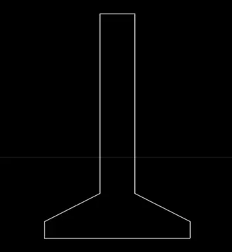
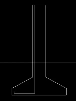
STEP 2:
- Enter L in command box and switch on orthomode.
- Enter 0.42,2.00 as first point in command box.
- Place the cursor downwards and enter @0, -1.96 as next point in the command box.
- Place the cursor left side and enter @-0.38,0 as next point in the command box.
- Place the cursor upwards and enter @0,0.04 as next point in the command box.
- Press ENTER or Click CLOSE in the command box.
STEPS 3:
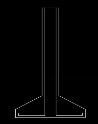
- Enter O in the command box which is OFFSET.
- Enter 0.16 as offset distance in command box.
- Select the line of 1.96 dimension and click it at the 0.16 spacing in opposite side.
- Press ENTER or click EXIT in command box.
- Enter L in command box.
- Enter 0.58,0.04 as first point in command box.
- Place the cursor right side and enter @0.38,0 as next point in command box.
- Place the cursor upwards and enter @0,0.04 as next point in command box.
- Press ENTER or click CLOSE in command box.
STEP 4:
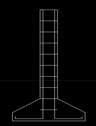
- Enter O in command box which is OFFSET.
- Enter 0.20 as offset distance in command box.
- Select the top line in the diagram.
- Fix it in the 0.20 distance.
- Select the next line and fix it in the 0.20 distance.
- Do the same step for 7 times.
- Press ENTER or click EXIT in command box.
STEP 5:
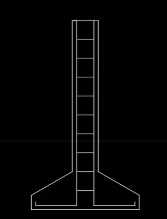
- Enter TR in command box which is used to trim objects.
- Press ENTER.
- Click EDGE in the command box.
- Click NO EXTEND in the command box.
- Click the extruded lines of 0.20 spacing.
- Press ENTER.
STEP 6:
- Enter DIMS in the command box.
- Click Modify.
- Click SYMBOLS AND ARROWS. Enter 0.05 in Arrow size.
- Click TEXT. Enter 0.05 in Text height.
- Click OK.
- Select STANDARD in Style. Click SET CURRENT. Click close.
- Enter DIM in command box.
- Click the first point and second point of the object. Drag it to the desired location. The dimension will be fixed in the preferred location in the workspace.
- Drag the dimension of all the objects in the workspace which are located in the given diagram.
- Enter TEXT in command box.
- Enter 0.1 as text height.
- Enter 0 as text rotation angle in command box.
- Press ENTER.
- Enter the text given in the diagram in the workspace.
- Press ENTER.
RESULT:
C.S of isolated footing is created by Lines using AutoCAD. The step-by-step procedure for creating cross section of isolated footing is also explained. The Dimension and heading are also entered in the diagram.
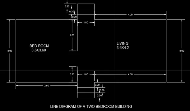
C3) LINE DIAGRAM OF A TWO BEDROOM BUILDING
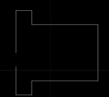
AIM: To create line diagram of a Two bed room building using AutoCAD.
INTRODUCTION: The line diagram of a Two bed room building using AutoCAD is created by Lines. The procedure and result should be written after creating the line diagram of a Two bed room building.
PROCEDURE:
STEP 1:
- Open the AutoCAD software and click start Drawing tab.
- Enter UNITS in command box.
- Select DECIMAL in TYPE, 0.00 in PRECISION and METERS in UNITS TO SCALE INSERTED CONTENT. Press OK.
- Switch on orthomode.
- Enter L in command box.
- Enter 0,0 as first point in the command box.
- Turn on orthomode.
- Place the cursor downwards and enter @0, -1.80 as first point in command box.
- Place the cursor right side and enter @1.00,0 as next point in command box.
- Place the cursor upwards and enter @0,0.90 as next point in command box.
- Place the cursor right side and enter @4.20,0 as next point in command box.
- Place the cursor upwards and enter @0,3.60 as next point in command box.
- Place the cursor left side and enter @-4.20,0 as next point in command box.
- Place the cursor upwards and enter @0,0.90 as next point in command box.
- Place the cursor left side and enter @-1.00,0 as next point in command box.
- Place the cursor downwards and enter @0, -2.70 as next point in command box.
- Press ENTER or click CLOSE in the command box.
STEP 2:
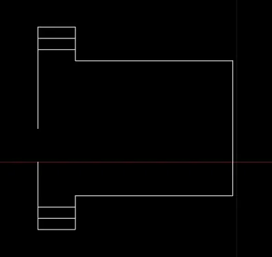
- Enter O in command box which is OFFSET.
- Enter 0.30 as offset distance in command box.
- Select the upper line of the diagram.
- Fix it at 0.30 spacing.
- Select the next line of the diagram downwards.
- Fix it at 0.30 spacing.
- Select the lower line of the diagram.
- Fix it at 0.30 spacing.
- Select the next line of the diagram upwards.
- Fix it at 0.30 spacing.
- Press ENTER or click EXIT in command box.
STEP 3:
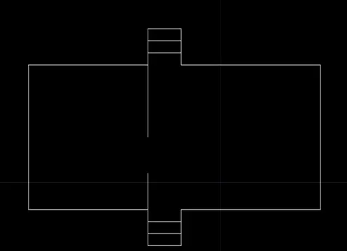
- Enter L in command box.
- Enter 0,2.70 as first point in command box.
- Place the cursor left side and enter @-3,60,0 as next point in command box.
- Place the cursor downwards and enter @0, -3.60 as next point in command box.
- Place the cursor right side and enter @3,60,0 as next point in command box.
- Press ENTER.
STEP 4:
- Enter DIMS in the command box.
- Click Modify.
- Click SYMBOLS AND ARROWS. Enter 0.10 in Arrow size.
- Click TEXT. Enter 0.10 in Text height.
- Click OK.
- Select STANDARD in Style. Click SET CURRENT. Click close.
- Enter DIM in command box.
- Click the first point and second point of the object. Drag it to the desired location. The dimension will be fixed in the preferred location in the workspace.
- Drag the dimension of all the objects in the workspace which are located in the given diagram.
- Enter TEXT in command box.
- Enter 0.15 as text height.
- Enter 0 as text rotation angle in command box.
- Press ENTER.
- Enter the text given in the diagram in the workspace.
- Press ENTER.
RESULT:
The line diagram of a Two bed room building is created by Lines using AutoCAD. The step-by-step procedure for creating the line diagram of a Two bed room building is also explained. The Dimension and heading are also entered in the diagram.
C4) C.S. OF LOAD BEARING WALL SHOWING FOUNDATION DETAILS
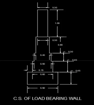
AIM: To create C.S of load bearing wall showing foundation details using AutoCAD.
INTRODUCTION: The C.S of load bearing wall showing foundation details using AutoCAD is created by Lines and Rectangles. The procedure and result should be written after creating the C.S of load bearing wall showing foundation details.
PROCEDURE:
STEP 1:
- Open the AutoCAD software and click start Drawing tab.
- Enter UNITS in command box.
- Select DECIMAL in TYPE, 0.00 in PRECISION and METERS in UNITS TO SCALE INSERTED CONTENT. Press OK.
- Enter REC in the command box.
- Enter first corner point as 0,0 in the command box.
- Click dimensions in the other corner point.
- Enter 0.90 in length for rectangles in the command box.
- Enter 0.45 in width for rectangles in the command box.
- Click the moving rectangle in the upper side on the workspace.

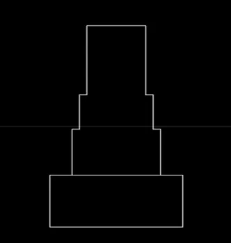
STEP 2:
- Enter L in command box.
- Switch on ORTHOMODE.
- Enter 0.15,0.45 as first point in command box.
- Place the cursor upwards and enter @0,0.40 as next point in command box.
- Place the cursor right side and enter @0.05,0 as next point in command box.
- Place the cursor upwards and enter @0,0.30 as next point in command box.
- Place the cursor right side and enter @0.05,0 as next point in command box.
- Place the cursor upwards and enter @0,0.60 as next point in command box.
- Place the cursor right side and enter @0.40,0 as next point in command box.
- Place the cursor downwards and enter @0, -0.60 as next point in command box.
- Place the cursor right side and enter @0.05,0 as next point in command box.
- Place the cursor downwards and enter @0, -0.30 as next point in command box.
- Place the cursor right side and enter @0.05,0 as next point in command box.
- Place the cursor downwards and enter @0, -0.40 as next point in command box.
- Press ENTER or click CLOSE in command box.
STEP 3:
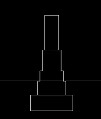
- Enter L in command box.
- Enter 0.30,1.75 as first point in command box.
- Place the cursor upward and enter @0,1.00 as next point in command box.
- Place the cursor right side and enter @0.30,0 as next point in command box.
- Place the cursor downward and enter @0, -1.00 as next point in command box.
- Press ENTER or click CLOSE in command box.
STEP 4:
- Enter DIMS in the command box.
- Click Modify.
- Click SYMBOLS AND ARROWS. Enter 0.05 in Arrow size.
- Click TEXT. Enter 0.05 in Text height.
- Click OK.
- Select STANDARD in Style. Click SET CURRENT. Click close.
- Enter DIM in command box.
- Click the first point and second point of the object. Drag it to the desired location. The dimension will be fixed in the preferred location in the workspace.
- Drag the dimension of all the objects in the workspace which are located in the given diagram.
- Enter TEXT in command box.
- Enter 0.1 as text height.
- Enter 0 as text rotation angle in command box.
- Press ENTER.
- Enter the text given in the diagram in the workspace.
- Press ENTER.
RESULT:
The C.S of load bearing wall showing foundation details is created by Lines and Rectangles using AutoCAD. The step-by-step procedure for creating the C.S of load bearing wall showing foundation details is also explained. The Dimension and heading are also entered in the diagram.
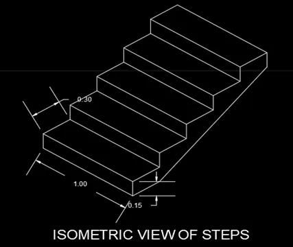
C5) ISOMETRIC VIEW OF STEPS
AIM: To create isometric view of steps using AutoCAD.
INTRODUCTION: Isometric view of steps using AutoCAD is created by Lines. The procedure and result should be written after creating the isometric view of steps.
PROCEDURE:
STEP 1:
- Open the AutoCAD software and click start Drawing tab.
- Enter UNITS in command box.
- Select DECIMAL in TYPE, 0.00 in PRECISION and METERS in UNITS TO SCALE INSERTED CONTENT. Press OK.
- Type DS in command box
- Put snap off and grid off. Click isometric snap on.
- Switch on ORTHOMODE.
- Click Isometric left in the status bar.
- Enter L in command box.
- Enter 0,0 as first point in command box.
- Place the cursor upwards and enter 0.15 as next point in command box.
- Place the cursor right side and enter 1.00 as next point in command box.
- Place the cursor downwards and enter 0.15 as next point in command box.
- Place the cursor left side and enter 1.00 as next point in command box.
- Press ENTER or click CLOSE in command box.
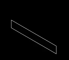
STEP 2:
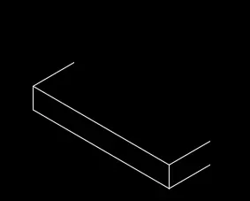
- Click Isometric right in the status bar.
- Enter L in command box.
- Click on upper top corner of the diagram.
- Enter 0.30 as first point in command box.
- Enter CO in command box which is COPY.
- Select the line of 0.30 length.
- Press ENTER.
- Click the basepoint as upper top corner.
- Click it at 1.00 distance at other point.
- Enter CO in command box.
- Select the line of 0.30 length at lower top corner of the diagram.
- Click it at 0.15 distance at lower point.
- Press ENTER.
STEP 3:
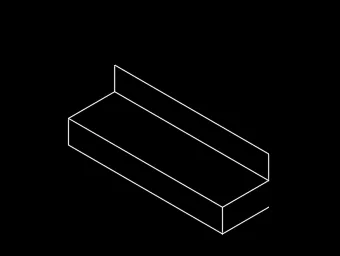
- Enter CO in command box.
- Select the rectangular box.
- Press ENTER.
- Click the baseline as lower corner of the rectangle.
- Click it after the two straight lines and fix it.
STEP 4:
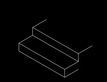
- Enter CO in command box.
- Select the two straight lines opposite to each other.
- Press ENTER.
- Click the top corner of the rectangle as basepoint.
- Fix the two lines after the second rectangular box.
STEP 5:
- Enter CO in command box.
- Again, copy the rectangular box and two opposite straight lines.
- Fix 3 rectangular boxes and 6 lines
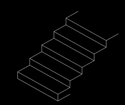
STEP 6:
- Enter CO in command box.
- Select the upper line in the last rectangular box.
- Click the last rectangle’s top corner point.
- Fix it after two opposite lines.
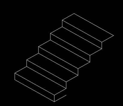
STEP 7:
- Enter CO in command line.
- Select the right side 0.30 dimension line.
- Click the lower top corner of rectangle as basepoint.
- Fix it below at a distance of 0.15.
- Switch off ORTHOMODE.
- Enter L in command box.
- Connect the two unconnected lines.
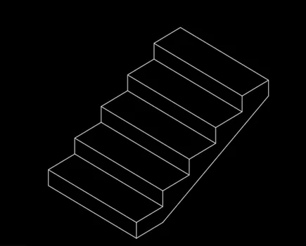
STEP 8:
- Enter DIMS in the command box.
- Click Modify.
- Click SYMBOLS AND ARROWS. Enter 0.05 in Arrow size.
- Click TEXT. Enter 0.05 in Text height.
- Click OK.
- Select STANDARD in Style. Click SET CURRENT. Click close.
- Enter DIM in command box.
- Click the first point and second point of the object. Drag it to the desired location. The dimension will be fixed in the preferred location in the workspace.
- Drag the dimension of all the objects in the workspace which are located in the given diagram.
- Enter TEXT in command box.
- Enter 0.1 as text height.
- Enter 0 as text rotation angle in command box.
- Press ENTER.
- Enter the text given in the diagram in the workspace.
- Press ENTER.
RESULT:
Isometric view of steps is created by Lines using AutoCAD. The step-by-step procedure for creating the Isometric view of steps is also explained. The Dimension and heading are also entered in the diagram.
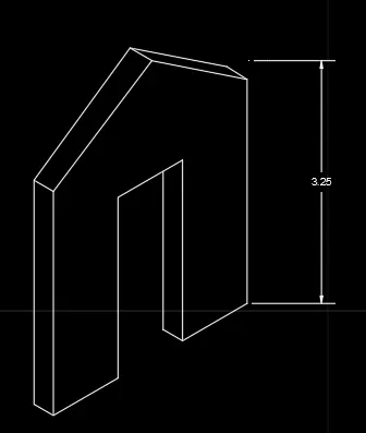
C6) ISOMETRIC VIEW OF GABLE WALL
AIM: To create isometric view of Gable wall using AutoCAD.
INTRODUCTION: Isometric view of Gable wall using AutoCAD is created by Lines. The procedure and result should be written after creating the isometric view of Gable wall.
PROCEDURE:
STEP 1:
- Open the AutoCAD software and click start Drawing tab.
- Enter UNITS in command box.
- Select DECIMAL in TYPE, 0.00 in PRECISION and METERS in UNITS TO SCALE INSERTED CONTENT. Press OK.
- Switch on orthomode in status bar.
- Type DS in command box
- Put snap off and grid off. Click isometric snap on.
- Switch on isometric left in status bar.
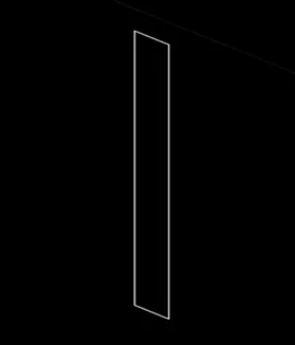
- Enter L in command box.
- Enter 0,0 as first point in command box.
- Place the cursor upward and enter 3.00 as next point in command box.
- Place the cursor left side and enter 0.30 as next point in command box.
- Place the cursor downward and enter 3.00 as next point in command box.
- Place the cursor right side and enter 0.30 as next point in command box.
- Press ENTER or click CLOSE in command box.
STEP 2:
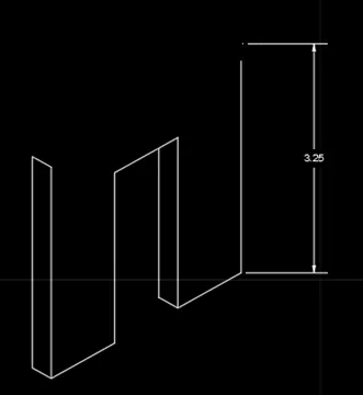
- Switch on isometric right in the status bar.
- Enter L in command box.
- Click on the top lower corner point.
- Place the cursor right side and enter 3.00 as next point in command box.
- Place the cursor downward and enter 3.00 as next point in command box.
- Place the cursor left side and enter 1.00 as next point in command box.
- Place the cursor upward and enter 2.42 as next point in command box.
- Place the cursor left side and enter 1.00 as next point in command box.
- Place the cursor downward and enter 2.42 as next point in command box.
- Place the cursor left side and enter 1.00 as next point in command box.
- Press ENTER or click CLOSE in command box.

STEP 3:
- Switch on isometric left.
- Enter L in command box.
- Click the third point from the left side of the bottom line.
- Place the cursor left side and enter 0.30 as next point in command box.
- Place the cursor upwards and enter 2.12 as next point in command box.
- Press ENTER or click CLOSE in command box.

STEP 4:
- Place the cursor on the centre connecting line and delete it.
- Enter DIMS in the command box.
- Click Modify.
- Click SYMBOLS AND ARROWS. Enter 0.10 in Arrow size.
- Click TEXT. Enter 0.10 in Text height.
- Click OK.
- Select STANDARD in Style. Click SET CURRENT. Click close.
- Enter DIM in command box.
- Click the first point and second point of the object. Drag it to the desired location. The dimension will be fixed in the preferred location in the workspace.
- The dimension of 3.25 is dragged and fixed.
STEP 5:
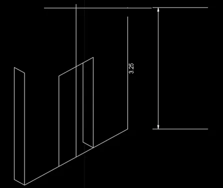
- Turn on isometric right in status bar.
- Enter L in command box.
- Click the lower left corner of the door and connect it with the other point of the door.
- Press ENTER or click CLOSE in command box.
- Enter L in command box.
- Click it to the left point of the dimension line of 3.25.
- Extend the line to the left side.
- Press ENTER or click CLOSE in command box.
- Enter L in command box.
- Click on the midpoint of the door.
- Extend the line upwards and click it where the midpoint and dimension line intersect.
STEP 6:
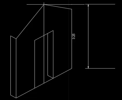
- Switch on isometric right and switch off orthomode.
- Click it on the top lower corner of the rectangular box and fix it on the intersection line.
- Then close it to the end point at the other side.
STEP 7:
- Delete the vertical midline, horizontal midline and extension line of 3.25 dimension.
- Enter CO in command box.
- Select the left side lower line of the mount
- Press ENTER.
- Click the basepoint as top lower corner of rectangle and fix it at top corner of rectangle.
- Switch on orthomode and isometric left.
- Click on the centre point of the mount.
- Place the cursor left side and connect it to the upper line.
- Press ENTER or click CLOSE in command box.
- Enter CO in command box.
- Click on the right side lower line in the mount.
- Press ENTER.
- Click the basepoint as lower centre point of mount and fix it at the upper centre point.
- Enter L in command box.
- Click it on the upper right side line of the mount and connect it with the end point at the other side.
STEP 8:
- Enter DIMS in the command box.
- Click Modify.
- Click SYMBOLS AND ARROWS. Enter 0.10 in Arrow size.
- Click TEXT. Enter 0.10 in Text height.
- Click OK.
- Select STANDARD in Style. Click SET CURRENT. Click close.
- Enter DIM in command box.
- Click the first point and second point of the object. Drag it to the desired location. The dimension will be fixed in the preferred location in the workspace.
- Drag the dimension of all the objects in the workspace which are located in the given diagram.
- Enter TEXT in command box.
- Enter 0.15 as text height.
- Enter 0 as text rotation angle in command box.
- Press ENTER.
- Enter the text given in the diagram in the workspace.
- Press ENTER.
RESULT:
Isometric view of Gable wall is created by Lines using AutoCAD. The step-by-step procedure for creating the Isometric view of Gable wall is also explained. The Dimension and heading are also entered in the diagram.