Creating a Residence Layout, Seating plan, Toilet and Utility room plan using AutoCad
1) RESIDENCE PLAN
AIM: To create the layout of a residence using AutoCAD.
INTRODUCTION: The layout of a residence using AutoCAD is created by Lines. The procedure and result should be written after creating the layout of a residence.
PROCEDURE:
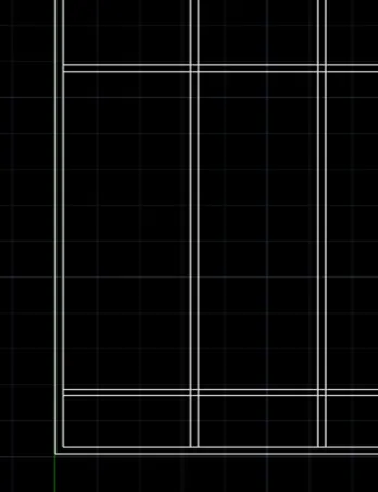
STEP 1:
- Open the AutoCAD software and click start Drawing tab.
- Enter UNITS in command box.
- Select ENGINEERING in TYPE, 0’0.0” in PRECISION and INCHES in UNITS TO SCALE INSERTED CONTENT. Press OK.
- Switch on ORTHOMODE.
- Enter LIMITS in command box. Enter 0’,0’ in lower left corner and 100’,100’ in upper right corner.
- Enter Z in command box and enter A in the command box or Click All in it.
- Enter XL in command box and Enter H. Place the line on the workspace and click escape.
- Enter XL in command box and Enter V. Place the line on the workspace and click escape.
- Enter TR in command box. Press ENTER and delete the left line and downward line. Press ENTER.
- Enter O in command box. Enter 9” as offset distance and Press ENTER. Select the horizontal downward line and drag it inside. Select the vertical upward line and drag it inside.
- Enter TR in command. Press ENTER and delete the horizontal and vertical line between two offset lines.
- Enter O in command box and Enter 6’ as offset distance. Select inner horizontal line and drag it upper side.
- Enter O in command box and Enter 9” as offset distance. Select the 6’ line and drag it above.
- Enter O and enter 12’6.0” as offset distance. Select the vertical outer line and drag it horizontally.
- Enter O and enter 9” as offset distance. Select the 12’6.0” line and drag it before it.
- Enter O and enter 25’ as offset distance. Select the vertical inner line and drag it horizontally.
- Enter O and enter 9” as offset distance. Select the 25’ line and drag it before it.
- Enter O in command box and Enter 43’6.5” as offset distance. Select inner horizontal line and drag it upper side.
- Enter O and enter 9” as offset distance. Select the 43’6.5” line and drag it above it.
STEP 2:
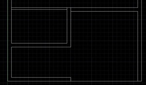
- Enter TR in command box. Press ENTER and delete the extra lines outside the plan.
- Enter EX in command box and select all the lines to be extended.
- Enter TR in command box. Press ENTER and delete all the lines into the walls.
- Enter TR in command box. Press ENTER and delete the horizontal inner lines in parking.
- Enter EX in command and extend the inner vertical right side line.
- Enter O in command box and enter 13’9.5” as offset distance. Select the lower horizontal line and drag it upwards.
- Enter O and enter 9”. Select the offset line of 13’9.5” and drag it above from it. Press ENTER or Click EXIT.
- Enter TR in command box and press ENTER. Delete all the lines which are not required.
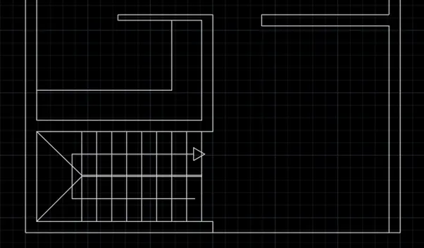
- Enter F in command and select RADIUS. Enter 0 as fillet radius. Select the two lines to be connected in stairs.
- Enter O and enter 6’8”. Select the stairs upper line and drag it upwards. Again O and enter 4.5”. Drag it upward. Click EXIT or press ENTER.
STEP 3:
- Enter O and enter 6’4”. Select the left outer line of kitchen and drag inwards.
- Enter TR in command box and press ENTER. Delete the lines which are unwanted.
- Enter O and enter 10’11.4”. Select the inner vertical left side line and drag it inwards.
- Enter O and enter 1’. Select the 10’11.4” line and drag it before.
- Repeat step 4 for 8 more times.
- Enter O and enter 3’. Select inner horizontal downward line and drag it upwards. Enter 1” and select it to drag upper side.
- Switch off ORTHOMODE and select the inner lowest corner, middle point of stairs and inner upper corner of stairs. Press ENTER.
- Switch on ORTHOMODE and click on starting point. Enter 3 in polygon command. Draw an arrow.
- Enter O and enter 2’. Select upper line of stairs and drag it above. Select the right side inner line of kitchen and drag it former.
- Enter O and enter 3’3”. Select the outer line of kitchen and drag it behind it.
- Enter TR and press ENTER. Delete the unwanted lines.
STEP 4:
- Enter O and enter 18’0.5”. Select outer line of stairs. Drag it above.
- Enter O and type 4.5”. Select the 18’0.5” line and drag it below.
- Enter O and type 11’. Select the parking outer line and drag it above.
- Enter O and type 4.5”. Darg it above 11’ line.
- Enter O and type 8’3”. Select the left inner line and drag it behind it.
- Enter O and type 4.5”. Select the 8’3” line and drag it behind.
- Enter O and type 8’1.5”. Select the right inner line and drag it former.
- Enter O and type 4.5”. Select the 8’1.5” line and drag it before.
- Enter O and type 4’6”. Select the outer horizontal line of toilet 1. Drag it above and also select outer horizontal line of toilet 2.
- Enter O and enter 4.5”. Select offset line and drag above it. Select offset line of toilet 2.
- Enter TR and press ENTER. Delete the unwanted lines.
- Enter F and Press ENTER. Connect the lines to make corner for toilet 1 and toilet 2.
- Enter O and enter 3’ of toilet 1. Select the right side inner lines.
- Enter O and type 2’6” of toilet 2. Select the horizontal inner lines of toilet 2.
- Enter TR and press ENTER. Delete the unwanted lines.
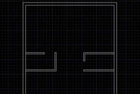
STEP 5:
- Enter O and type 11’7.5”. Select the inner line of plan. Drag it inside.
- Enter O and type 4.5”. Select the offset line. Drag it inside.
- Enter O and type 12’. Select the inner line of upper part of plan and drag below.
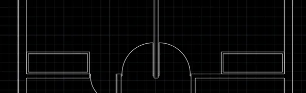
- Track midpoint of partition wall of parking and enter 1” as distance. Enter 6’8” as height.
- Enter C and click midpoint of extended line. Click the opposite side as end point.
- Enter TR and delete the unwanted lines of circle.
- Repeat steps 4,5 and 6 for Toilet 1, Toilet 2, Bed 1 and Bed 2.
- Enter REC. Click Toilet 1 left corner and click DIMENSIONS. Enter 5’9” as length and 2’ as width.
- Enter O and type 2”. Select the rectangle and drag it inside.
- Enter CO and select the rectangle. Click other endpoint at right side of Toilet 2.
STEP 6:
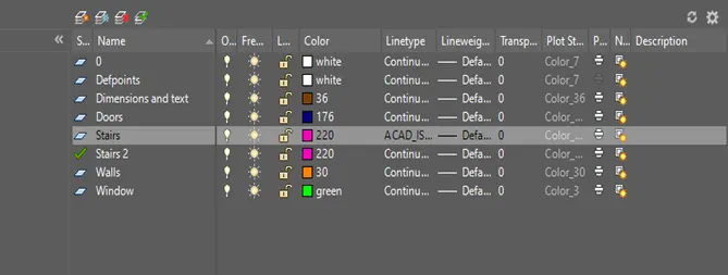
- Click LAYER PROPERTIES in RIBBON. Click NEW LAYER. Enter DIMENSIONS AND TEXT, DOORS, STAIRS, STAIRS 2, WALLS and WINDOW in NAME column.
- Select 36 INDEX COLOUR for DIMENSIONS AND TEXT, 176 for DOORS, 220 for STAIRS and also select ISO DASH LINE TYPE and 220 for STAIRS 2.
STEP 7:
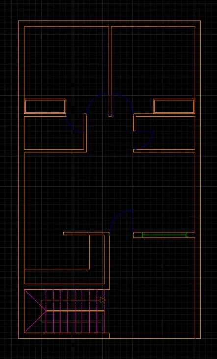
- Select the walls of plan and click walls in LAYER dropdown in RIBBON. Select respective objects and give their assigned colours.
- Select the stairs and click stairs and stairs 2. Enter LTSCALE in command and enter 0.3.
- Enter O and enter 1’3”. Again enter O and type 6’. Drag at 6’ distance. Click the midpoint of window left side and connect to other side midpoint of window.
- Select window in LAYER dropdown and assign its colour.
STEP 8:
- Enter DIMS in command box.
- Click MODIFY. In SYMBOLS and ARROWS, Enter ARROW SIZE as 1’.
- In TEXT, Enter TEXT HEIGHT as 1’.
- In PRIMARY UNITS, Click ENGINEERING in UNIT FORMAT, 0’0.0” in PRECISION.
- In LINES, Enter 1’ as EXTEND BEYOND LINES and 6.0” as OFFSET FROM ORIGIN. Click OK.
- Click SET CURRENT. Click CLOSE.
- Click DIMENSIONS AND TEXT dropdown in LAYER.
- Enter DIML in command box and drag the dimensions.
- Enter DT in command box. Enter 1’ as TEXT HEIGHT and 0 as TEXT ROTATION ANGE.
- Enter TEXT.
- Enter CO in command box. Copy the text and place it in another location.
- Enter TEXTEDIT in command box. Using this, editing in text can be done.
- Enter REC. Drag it outside. Enter 18’2.5” as length and 8’3.4” as width.
- Enter REC and enter 18’2.5” as length and 2’2.5” as width.
- Enter REC and enter 18’2.5” as length and 1’11.1” as width.
- Enter REC and enter 18’2.5” as length and 1’11.1” as width.
- Enter REC and enter 18’2.5” as length and 1’11.1” as width.
- Enter REC and enter 4’4.0” as length and 8’3.4” as width.
- Enter REC and enter 7’0.1” as length and 8’3.4” as width.
- Enter REC and enter 7’0.1” as length and 8’3.4” as width.
- Enter text using DT and copy the text. Edit it by using TEXTEDIT.
- Enter REC and enter 10’ as length and 5’ as width.
- Enter text using DT and copy the text. Edit it by using TEXTEDIT.
- Save the drawing and rename it as AUTOCAD CHALLENGE 4.
RESULT:
The layout of a residence is created by lines using AutoCAD. The step-by-step procedure for creating the layout of a residence is also explained. The Dimension is also entered in the diagram.

2) SEATING PLAN FOR AN OUTDOOR CANOPY
AIM: To create the seating plan for an outdoor canopy using AutoCAD.
INTRODUCTION: The seating plan for an outdoor canopy using AutoCAD is created by Lines and Circles. The procedure and result should be written after creating the seating plan for an outdoor canopy.
PROCEDURE:
STEP 1:
- Open the AutoCAD software and click start Drawing tab.
- Enter UNITS in command box.
- Select DECIMAL in TYPE, 0 in PRECISION and MILLIMETERS in UNITS TO SCALE INSERTED CONTENT. Press OK.
- Switch on ORTHOMODE.
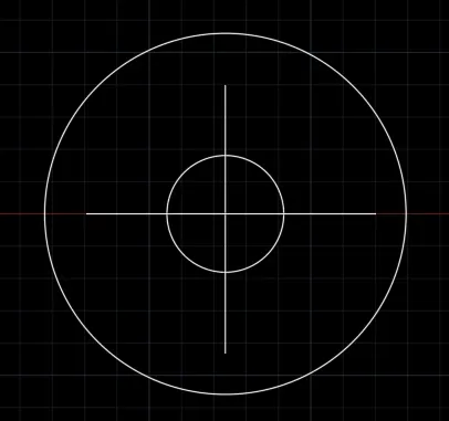
- Click CIRCLE, RADIUS from CIRCLE dropdown in RIBBON.
- Enter 0,0 as centre point.
- Enter 452 as RADIUS of the circle.
- Again select CIRCLE, RADIUS and enter 0,0 as centre point.
- Enter 1398 as RADIUS of the circle.
- Enter L in command box.
- Draw the line vertically passing through the centre of the circle. Press ENTER.
- Draw the line horizontally passing through the centre of the circle. Press ENTER.
STEP 2:
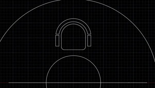
- Enter O and type 200 as offset distance. Select the centre vertical line and drag it at either side.
- Enter O and type 546 as offset distance. Select the centre horizontal line and drag it upwards.
- Enter O and type 550 as offset distance. Select the centre horizontal line and drag it upwards.
- Click CIRCLE, RADIUS in CIRCLE dropdown in RIBBON.
- Enter 0,778 as centre of the circle.
- Enter 200 as RADIUS of the circle.
- Enter TR in command box and press ENTER. Delete the lower half circle.
- Click CIRCLE, RADIUS in CIRCLE dropdown in RIBBON.
- Enter 0,1018 as centre of the circle.
- Enter 240 as RADIUS of the circle.
- Click CIRCLE, RADIUS in CIRCLE dropdown in RIBBON.
- Enter 0, 1070 as centre of the circle.
- Enter 292 as RADIUS of the circle.
- Enter TR in command box and press ENTER. Delete the lower half of both the circles.
- Enter O and type 261 as offset distance. Select the 550 mm distance line and drag it above.
- Enter TR and press ENTER. Delete the unwanted line intruding the seat.
- Enter O and type 20 as offset distance. Select the 261mm distance line and drag it downwards at either side.
- Enter L in command box.
- Click the 20 mm offset line and enter 180.
- Enter 20 and 180. Press ENTER or Click CLOSE.
- Enter L in command box.
- Click the 20 mm offset line and enter 180.
- Enter 20 and 180. Press ENTER or Click CLOSE.
- Enter TR and press ENTER. Select the unwanted lines.
STEP 3:
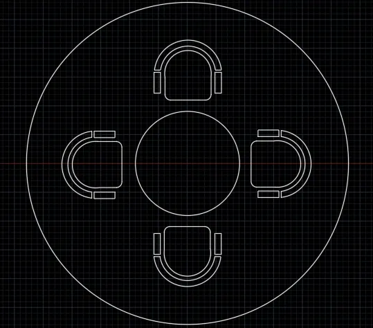
- Enter CO and press ENTER. Select seat which was created before.
- Select the horizontal lower line centre point as base point.
- Enter 1098 as second point.
- Enter RO in command box and select the copied seat.
- Enter 180 as rotation angle.
- Enter CO and press ENTER. Select seat which was created before.
- Select the centre point of seat curve as base point.
- Enter 1125 as second point.
- Enter RO in command box and select the copied seat.
- Enter 90 as rotation angle.
- Enter CO and press ENTER. Select seat which was created before which is left side seat.
- Select the horizontal lower line centre point as base point.
- Enter 1098 as second point.
- Enter RO in command box and select the copied seat.
- Enter 180 as rotation angle.
STEP 4:
- Enter DIMS in command box. Click MODIFY.
- In SYMBOLS and ARROWS, Enter ARROW SIZE as 100.
- In TEXT, Enter TEXT HEIGHT as 100.
- In PRIMARY UNITS, Click DECIMAL in UNIT FORMAT, 0 in PRECISION.
- In LINES, Enter 10 as EXTEND BEYOND LINES and 30 as OFFSET FROM ORIGIN. Click OK.
- Click SET CURRENT. Click CLOSE.
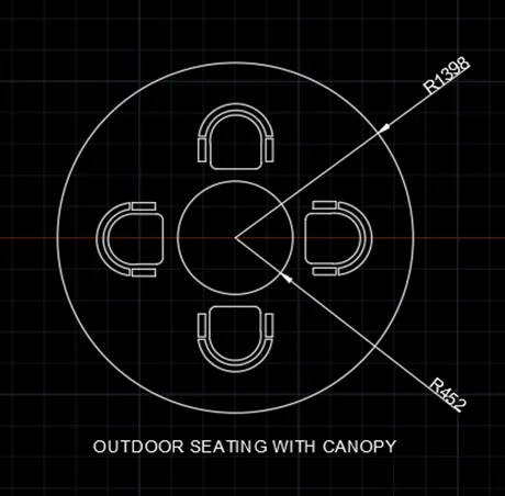
- Enter DIMRAD in command box and drag the dimensions.
- Enter DT in command box. Enter 100 as TEXT HEIGHT and 0 as TEXT ROTATION ANGE.
- Enter TEXT.
- Save the drawing and rename the file.
RESULT:
The seating plan for an outdoor canopy is created by lines and circles using AutoCAD. The step-by-step procedure for creating the seating plan for an outdoor canopy is also explained. The Dimension and heading are also entered in the diagram.
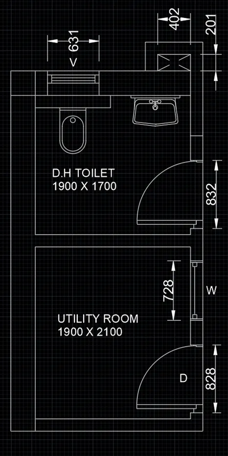
3)PART PLAN FOR THE TOILERS AND UTILITIES ROOM
AIM: To create the part plan for the toilers and utilities room using AutoCAD.
INTRODUCTION: The part plan for the toilers and utilities room using AutoCAD is created by Lines and Circles. The procedure and result should be written after creating the part plan for the toilers and utilities room.
PROCEDURE:
STEP 1:
- Open the AutoCAD software and click start Drawing tab.
- Enter UNITS in command box.
- Select DECIMAL in TYPE, 0 in PRECISION and MILLIMETERS in UNITS TO SCALE INSERTED CONTENT. Press OK.
- Switch on ORTHOMODE.
- Enter LIMITS in command box. Enter 0’,0’ in lower left corner and 5000,5000 in upper right corner.
- Enter Z in command box and enter A in the command box or Click All in it.
- Enter XL in command box and Enter H. Place the line on the workspace and click escape.
- Enter XL in command box and Enter V. Place the line on the workspace and click escape.
- Enter TR in command box. Press ENTER and delete the left line and downward line. Press ENTER.
- Enter O in command box. Enter 300 as offset distance and Press ENTER. Select the vertical upward line and drag it inside.
- Enter O in command box. Enter 150 as offset distance and Press ENTER. Select the horizontal downward line and drag it inside.
- Enter TR in command. Press ENTER and delete the horizontal and vertical line between two offset lines.
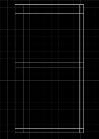
- Enter O in command box and type 1900 as offset distance. Press ENTER. Select the inner vertical line and drag it behind it.
- Enter O and type 150 as offset distance. Press ENTER. Select the 1900 mm distance line and drag it behind.
- Enter O and type 2100 as offset distance. Press ENTER. Select the inside horizontal line and drag it above.
- Enter O and type 150 as offset distance. Press ENTER. Select the 2100 mm distance line and drag it above.
- Enter O and type 1700 as offset distance. Press ENTER. Select the upper horizontal line of 2100 mm distance and drag it above.
- Enter O and type 300 as offset distance. Press ENTER. Select the 1700 mm distance line and drag it above.
- Enter TR and press ENTER. Delete all the extruded lines of the plan.
STEP 2:
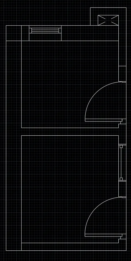
- Enter L in command box.
- Click the inner horizontal line of toilet upper part right corner point.
- Enter 201 as next point.
- Enter 402 as next point.
- Enter 201 as next point.
- Enter O and type 150 as offset distance.
- Select the individual line of the created rectangle and drag those lines outwards.
- Enter F and click RADIUS. Enter 0 as FILLET RADIUS. Select the unconnected lines.
- Enter L in command box.
- Switch off ORTHOMODE.
- Click the corner point of inner rectangle created before and connect it to diagonal point. Repeat same for opposite side.
- Enter REC and click the corner on the crossed line and placed over it.
- Enter TR and delete the lines inside the created rectangle.
- Enter O and type 150 as offset distance. Select the line above first corner point and drag it inwards.
- Enter O and type 631 as offset distance. Select 150 mm offset line and drag it inwards.
- Enter O and type 50 as offset distance. Select the upper line and drag it below.
- Enter O and type 35 as offset distance. Select the upper line and drag it below. Repeat this step two more times.
- Enter TR and delete the unwanted lines.
- Enter O and type 75 as offset distance. Select the inside horizontal line from lower side and drag it above.
- Enter O and type 828 as offset distance. Select the 75mm line and drag it above.
- Enter O and type 75 as offset distance. Select the inside horizontal line above utility room and drag it above.
- Enter O and type 832 as offset distance. Select the 75mm line and drag it above.
- Enter O and type 50 as offset distance. Select the 75mm line of lower line and drag it above.
- Enter O and type 50 as offset distance. Select the 50mm line and drag it above.
- Enter O and type 20 as offset distance. Select the 828mm line and drag it below.
- Enter O and type 110 as offset distance. Select the outer line of right vertical line and drag it inside.
- Enter O and type 80 as offset distance. Select the outer line of right vertical line and drag it inside.
- Enter C and click the point upper side and drag it to endpoint of other side.
- Enter TR and delete the lines.
- Enter O and type 50 as offset distance. Select the 75mm line and drag it above.
- Enter O and type 50 as offset distance. Select the 50mm line and drag it above.
- Enter O and type 20 as offset distance. Select the 832mm line and drag it below
- Enter C and click the point upper side and drag it to endpoint of other side.
- Enter TR and delete the lines.
- Enter O and type 300 as offset distance. Select the 828mm line and drag it above.
- Enter O and type 728 as offset distance. Select the 300mm line and drag it above.
- Enter O and type 20 as offset distance. Select the 300mm line and drag it above and select the 728mm line and drag it below.
- Enter O and type 54 as offset distance. Select the inner vertical line and drag it inside.
- Enter REC and click the corner point outside the plan. Enter 50 as length and width.
- Enter CO and select the square. Drag it inside the window and place it on the offset line. Again copy and place it at the opposite side.
- Enter TR and delete the intruded lines.
STEP 3:
- Enter O and type 920 as offset distance. Select the inner vertical line and drag it inside.
- Enter O and type 150 as offset distance. Select the inner horizontal line and drag it below.
- Enter O and type 30 as offset distance. Select the inner horizontal line and drag it below.
- Enter O and type 370 as offset distance. Select the 30mm line and drag it below.
- Enter O and type 300 as offset distance. Select the inner vertical line and drag it inside.
- Enter O and type 160 as offset distance. Select the 300mm line and drag it inside.
- Enter O and type 320 as offset distance. Select the 300mm line and drag it inside.
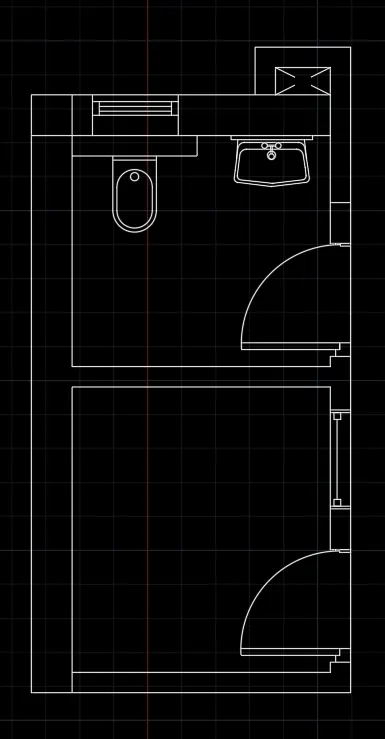
- Select CENTRE, START, END in ARC dropdown in RIBBON.
- Click centre point, start point and end point of the toilet. ARC is created.
- Enter O and type 30 as offset distance. Select the arc and drag it inside.
- Select the 300 mm line and 320 mm line. Drag it inside the objects.
- Select CENTRE, START, END in ARC dropdown in RIBBON.
- Click centre point, start point and end point of the toilet. ARC is created.
- Enter C and click outside the plan. Enter 30 as radius of the circle.
- Enter CO and select the circle. Select base point and place it centre of toilet.
- Enter O and type 250 as offset distance. Select the 920mm line and drag it inside.
- Enter O and type 600 as offset distance. Select the 250mm line and drag it inside.
- Enter O and type 30 as offset distance. Select the inner line of plan and drag it inside.
- Enter O and type 20 as offset distance. Select 30mm line and drag it inside.
- Enter O and type 50 as offset distance. Select the 20mm line and drag it inside.
- Switch off ORTHOMODE.
- Enter L and click corner point. Enter 230 as next point.
- Enter 261 as next point and 261 as next point.
- Close the line by connecting the endpoint.
- Enter O and type 20 as offset distance. Select the lines and drag it outside.
- Enter F and type 50 as fillet radius. Select the upper unconnected lines.
- Enter F and type 30 as fillet radius. Select the lower unconnected lines.
- Enter O and type 245 as offset distance. Select the 250 mm line and drag it behind.
- Enter O and type 45 as offset distance. Select the 245 mm line and drag it behind.
- Enter O and type 10 as offset distance. Select the 45 mm line and drag it behind.
- Enter O and type 100 as offset distance. Select the 245 mm line and drag it behind.
- Enter O and type 75 as offset distance. Select the inner line and drag it below.
- Enter O and type 10 as offset distance. Select the 75mm line and drag it below.
- Enter O and type 55 as offset distance. Select the 10mm line and drag it below.
- Enter TR and delete the unwanted lines.
- Enter C and click centre point as outside the plan.
- Enter 20 as radius of the circle.
- Enter CO and select the circle. Click the base point and drag it into the wash basin.
- Enter CO and select the circle. Click the base point and drag it into the wash basin at the other point.
- Enter C and click centre point as outside the plan.
- Enter 30 as radius of the circle.
- Enter CO and select the circle. Click the base point and drag it into the wash basin at the centre point.
- Enter CO and select the 20 mm radius circle. Click the base point and drag it into the wash basin into the 30 mm radius circle.
- Enter L and draw diagonally outside the washbasin at either side.
STEP 4:
- Enter DIMS in command box.
- Click MODIFY. In SYMBOLS and ARROWS, Enter ARROW SIZE as 120.
- In TEXT, Enter TEXT HEIGHT as 120.
- In PRIMARY UNITS, Click DECIMAL in UNIT FORMAT, 0 in PRECISION.
- In LINES, Enter 70 as EXTEND BEYOND LINES and 120 as OFFSET FROM ORIGIN. Click OK.
- Click SET CURRENT. Click CLOSE.
- Click DIMENSIONS AND TEXT dropdown in LAYER.
- Enter DIML in command box and drag the dimensions.
- Enter DT in command box. Enter 120 as TEXT HEIGHT and 0 as TEXT ROTATION ANGE.
- Enter TEXT.
- Enter CO in command box. Copy the text and place it in another location.
- Enter TEXTEDIT in command box. Using this, editing in text can be done.
- Save the drawing and rename the file.
RESULT:
The part plan for the toilers and utilities room is created by lines and circles using AutoCAD. The step-by-step procedure for creating the part plan for the toilers and utilities room is also explained. The Dimension is also entered in the diagram.