Project 1 _Creating an Architectural plan for the provided plot size and develop relevant basic structural drawings
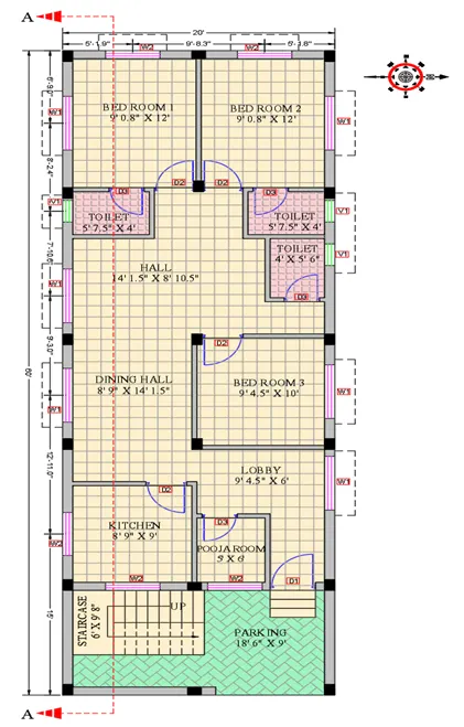
AIM: Design and Draft a layout of a residential building with the Plot Size: 60’x20’(18.3m x6m) Facing East.
Introduction: In this challenge i have draft the above meationed drawing i.e, Design and Draft a layout of a residential building with the Plot Size: 60’x20’(18.3m x6m) Facing East, using AutoCad. here in this challange i have attached all the drawings in a image format and with the proper procedure as possible.
The comman commands which are used in this challange are discussed below
Selecting of Tools:
- Line: Ribbon< Home< Line, Command: Line or L, Home< Draw< Line.
- Polyline: Ribbon< Home< Polyine, Command: polyline or pl, Home< Draw< polyline.
- Rectangle: Ribbon< Home< rectangle, Command: rectangle or rec, Home< Draw< rectangle.
- Ploygon: Ribbon< Home< Ploygon, Command: Ploygon or pol, Home< Draw< Ploygon.
- Circle: Ribbon< Home< Circle, Command: Circle or C, Home< Draw< Circle.
- Fillet: Ribbon< Home< Fillet, Command: Fillet or F, Home< modify< Fillet.
- Chamfer: Ribbon< Home< Chamfer, Command: Chamfer or cha, Home< modify<Chamfer.
- Move: Ribbon< Home< move, Command: move or M, Home< modify<Move.
- Copy: Ribbon< Home< Copy, Command: Copy or co, Home< modify<Copy.
- TRIM: Ribbon< Home< trim, Command: TRIM or TR, Home< modify
Procedure:
A. Architectural drawings:
Step 1: for creating the above Mentioned plan of a 3 BHK Resident in 60'x20', using line tool in autocad is discussed below,
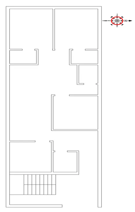
Procedure:
- open autocad 2019 and select a new file and saved as challange 5 and saved in the skill-lync folder.
- set the unit of drawing by giving command un in command and selected Engineering with precion 0'-0.0".
- select limit by giving command limmax and giving the limit 20',20' and entre.
- adjust the dimension size by giving command d and selecting the same unit as mentioned that is Engineering.
- Select the XL command and draft the two lines a vertical and horizontal and interset each other.
- Select the offset option and given the data as shown in the images.
- After giving the proper offset trim the excess.
- Give the command panel and select the trim option and trim the excess.
- creat a plan as shown in the question.
Step 2: Creating the layers in autocad is discussed below,
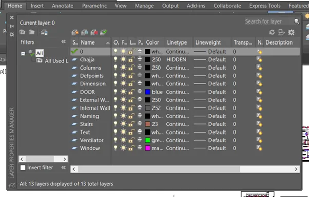
Procedure:
- Go to the ribbon panel select the layers properties
- Select the add new layer option.
- Edit the layer as I have given layer as doors, windows, external wall, internal wall etc..
- cretaing a layer that is go for a option create new layer.
- and now select the layer and right click and select as rename option and give the names.
- the names i have used as Door, window, ventilator wall etc.
- assign proper properties and colour which ever u like.
- Edit the required layers as wanted as shown in the above image.
Step 3: Creation of Columns and placing the columns in proper position in autocad is discussed below,
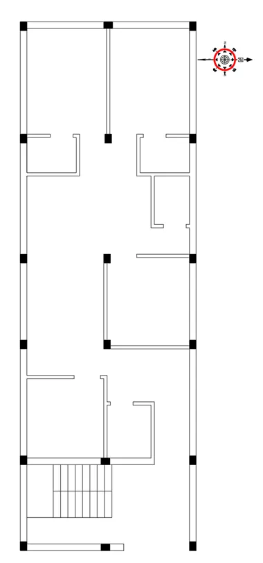
Procedure:
- Use Rectangle option and give the size as 9"x12" as shown in above figure.
- Hatch the created rec by using hatch command and select the concrete hatch with 100 as scale factor.
- Chose the colour in this i have selected black colour.
- Bolock the creted rec by using the command block and select the base point and select the component and give the name.
- I have given the name Column 9x12 in this drawing.
- and use copy tool and place the column in the proper position and alignment as shown in the figure.
- simillarly create another column with the dimension 9"x12" as shown in figure.
- use array tool and use path with proper spacing by selecting 3 components as shown above.
Step 4: Placing of Doors and Windows in proper position and applying of hatch,
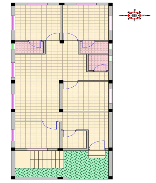
Procedure:
- create a door of size 3'4", 3', 2'7" of three types as shown.
- draw a line of size 3'4" and thick it by using ofset and use circle tool as shown.
- trim the excess of the circle and that is how u create a door
- Hatch the created rec by using hatch command and select the concrete hatch with 100 as scale factor.
- Chose the colour in this i have selected black colour.
- Bolock the creted door by using the command block and select the base point and select the component and give the name.
- I have given the name door d1 in this drawing.
- and use copy tool and place the column in the proper position and alignment as shown in the figure.
- simillarly create 2 more doors that is 3' and 2'7"as shown in figure.
- And give name as D2& D3 respectivilly.
- after creating the doors and windows place it in proper position as shown.
- use poly line command and create boundries of room hall etc.
- and take hatch command select the boundry and choose the proper colour.
- use solid hatch of different colour and apply the hatch as shown in figure.
Step 5: Completion of plan with proper naming and Dimension,
Procedure:
- After placing of doors and window now the time is for naming.
- select the Mtext and select the type of font colour and size of text and type the content what u want to show.
- after creating the prper name copy it by all the places where we want.
- Use move tool and place all the drawings drawn in the proper places.
- use Mtext option and type which ever required or shown.
- after editing the text copy the text and placed in columns or where ever required as shown above.
- edit the copied text by giving commant textedit and star editing the copied text.
- Now give the dimension as shown by using dimlinear command and give proper dimension.
- use dimcontinue option and place it where required.
- and now hatch the walls with using brick wall option and place in proper position.
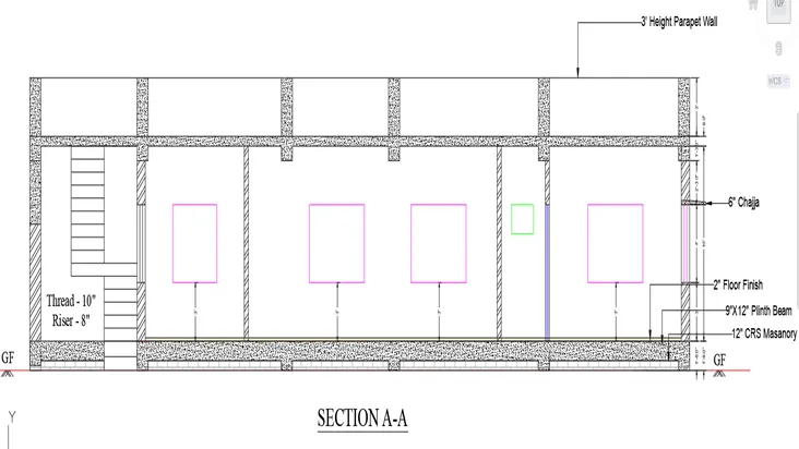
Step 6: Creation of Section A-A of the above showing plan.
Procedure:
- use xl command and select the plan that is edges of doors windows column and ventilator if showing.
- create a line as a ground floor line and trim the excess.
- draw the doors an windows if showing using line tool or trimming the extra lines.
- after completion of the gf now the whole section is copied and place as one above the other,
- as gf floors are simmilar in plan and dimension so copy it.
- after copieng give proper naming that is by using mtext option.
- select the Mtext and select the type of font colour and size of text and type the content what u want to show.
- after creating the prper name copy it by all the places where we want.
- Use move tool and place all the drawings drawn in the proper places.
- use Mtext option and type which ever required or shown.
- after editing the text copy the text and placed in columns or where ever required as shown above.
- edit the copied text by giving commant textedit and star editing the copied text.
- Now give the dimension as shown by using dimlinear command and give proper dimension.
- use dimcontinue option and place it where required.
- and now hatch the walls with using brick wall option and place in proper position.
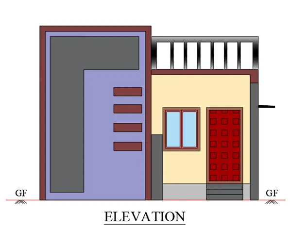
Step 6: Creation of Elevation of the above showing plan.
Procedure:
- use xl command and select the plan that is edges of doors windows column and ventilator if showing.
- create a line as a ground floor line and trim the excess.
- draw the doors an windows if showing using line tool or trimming the extra lines.
- after completion of the gf now the whole section is copied and place as one above the other,
- as ground floors are simmilar in plan and dimension so copy it.
- after copieng give proper naming that is by using mtext option.
- Now give the dimension as shown by using dimlinear command and give proper dimension.
- use dimcontinue option and place it where required.
- and now hatch the walls with using solid option and place in proper position.
B. Structural drawings:
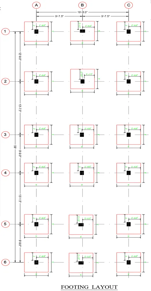
Step 1: Footing Layout:
Procedure:
- Columns which are placed on the plan copied it by using co command and place it where ever required.
- Now use XL Command and select vertical and click the centre of each columns.
- and use xl command and horizontal option and select the centre of each columns.
- select a rec command and give dimension 5' x 5' (as we dont have proper size).
- and select the centre of rectangle and start placing it on centre of each columns respetivelly.
- give different colour as in this case i have given red colour.
- select the dim linear and select the style as roman and place the dim where ever required.
- select the dimlinear and mak the centre to centre distance.
- by using dimcontinue option do it properly.
- select a circle command and select the radius as shoun for marking.
- select mtext option and place it in between the centre with proper anotation.
- and trim the excess of lines by using trim option.
Step 1: Column Layout:
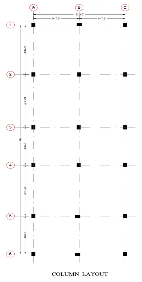
Procedure:
- Columns which are placed on the plan copied it by using co command and place it where ever required.
- Now use XL Command and select vertical and click the centre of each columns.
- and use xl command and horizontal option and select the centre of each columns.
- select the dim linear and select the style as roman and place the dim where ever required.
- select the dimlinear and mak the centre to centre distance.
- by using dimcontinue option do it properly.
- select a circle command and select the radius as shoun for marking.
- select mtext option and place it in between the centre with proper anotation.
- like A, B, C and vertical 1, 2, 3, 4, 5, 6 etc
- and trim the excess of lines by using trim option.
Step 1: Beam Layout:
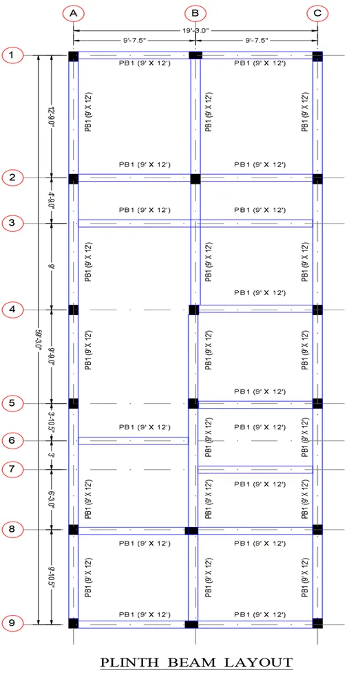
Procedure:
- Beams are drawn of size 9" as it ll be present below the wall.
- select the column layout and start drawing the beams of size 9" width as shown.
- check the walls and place the beams as shown in figure
- Columns which are placed on the plan copied it by using co command and place it where ever required.
- Now use XL Command and select vertical and click the centre of each columns.
- and use xl command and horizontal option and select the centre of each columns.
- select the dim linear and select the style as roman and place the dim where ever required.
- select the dimlinear and mak the centre to centre distance.
- by using dimcontinue option do it properly.
- select a circle command and select the radius as shoun for marking.
- select mtext option and place it in between the centre with proper anotation.
- like A, B, C and vertical 1, 2, 3, 4, 5, 6 etc
- and trim the excess of lines by using trim option.
- and use mtext option and write plinth beam and place it below.
- similarly use mtext and write pb-1 (9" x 12") the size of plinth beam assumed and place it below each drawn beam.
Result:
The above shown diagram is of the plan of a carpet area of size 20' x 60' which is facing East , it consist of 3BHK with parking in the front.
A complete plan with proper section is discussed above.