Project 1 _Creating an Architectural plan for the provided plot size and develop relevant basic structural drawings
AIM: To Design and Draft a layout of a residential building with given details
INTRODUCTION:
Given details
- Plot Size 60' x 20' ( 18.30m x 6.00m)
- Orientation- Facing East
Drawing to be developed
- Architectural drawings
a. Floor Plan
b. Elevation
c. Section
- Structural drawings
a. Footing Plan
b. Column Plan
c. Beam Plan
The drawing is drawn using Metric units with the given details using various commands in AutoCad.
The Residential building considered is a Ground floor 2BHK structure with staircase to roof terrace.
Building size is assumed as plot size.
External wall thickness considered is 230mm and internal wall thickness considered is 100mm.
The step wise procedure along with stage wise screenshots of the drawings area attached for reference.
PROCEDURE:
- Set the drawing to Metric units
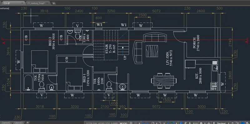
DRAWING FOR GROUND FLOOR PLAN:
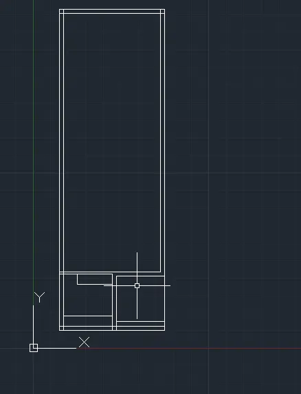
- Draw the plot boundaries of 18300mm x 6000mm for the building external wall.
- Offset the lines on inner side for 230mm for outer wall thickness
- Draw the Kitchen in South East corner.
- On the North east corner draw the Porch with steps.
- The internal wall thickness is 100mm
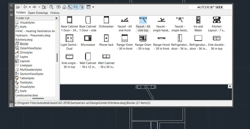
- Use the Design Center command for importing the blocks for furniture, sanitary ware etc. for ready use as shown in the screenshot below
- Draw the internal walls for bedrooms and bathrooms with 100mm thickness
- Create door size openings.
- Draw the door blocks of required sizes and paste it in the door openings as per the required orientation.
- Similarly draw the window blocks and paste in the window openings
- Paste in sanitaryware blocks imported from design center as required in the bathroom layout.
- Draw the staricase block.
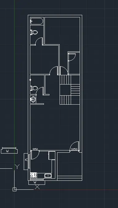
- Insert the furniture blocks as required
- Using MText write the Room names and the dimensions by setting the required font and text height.
- Change the lines to hidden by using Dashed line style and setting the line scale.
- Hatch command is used to show the floor tiles and the scale modified as required.
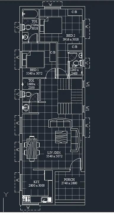
- Provide the dimensions using Dimlinear and Dimcontinue by setting the Dimstyle for font size and colour.
- Assign layers to walls, floor in the layer properties using required colours
- Show the North direction for the building.
- Write down the Title of drawing and scale at he bottom
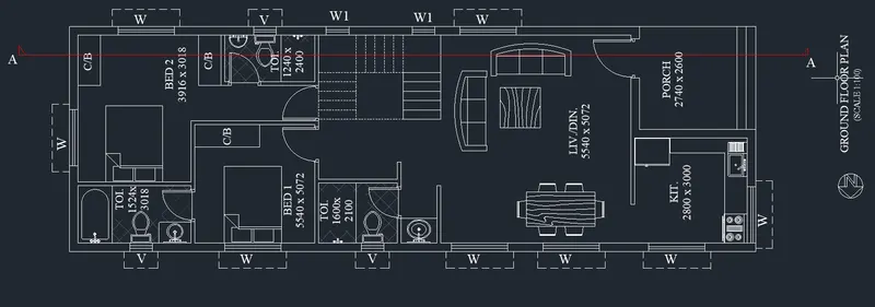
- Thus the Ground Floor Plan for residential drawing is completed
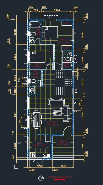
- The drawing without layer properties is shown in screenshot below
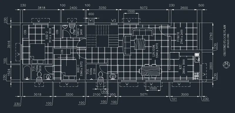
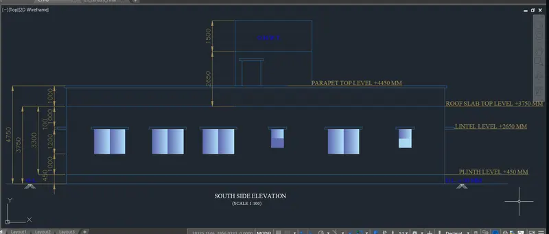
DRAWING FOR SOUTH SIDE ELEVATION:
- Rotate the ground floor plan by 90degrees with south side on the upper side.
- Draw rays from the wall lines, window lines along Y axis from the ground floor plan to project for drawing the elevation.
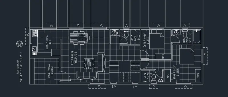
- Draw a line along X axis crossing all the vertical rays as a reference for the ground level.
- Offset the line by 450mm for the plinth line.
- Similarly offset the horizontal lines for sill, lintel, roof level, parapet level, head room and water tank levels.
- Trim the unwanted lines around the window openings to form windows in elevation.
- Draw the sunshades above the windows.
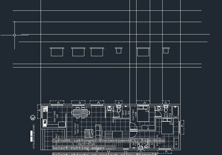
- Trim all the unwanted lines keeping the required lines for the building lines in elevation.
- Using gradient in hatch command the window glass can be shown.
- Using Leader command write down the different level details.
- Using dimlinear show the dimensions
- Show the ground level
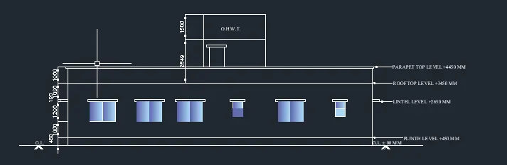
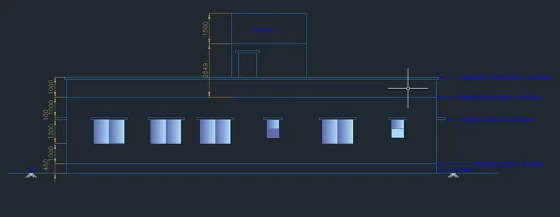
- Assign the layer for the outerlines of building in layer properties
- Thus the South Side Elevation of the building is completed.
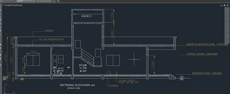
DRAWING SECTIONAL ELEVATION OF BUILDING:
- Rotate the plan with the section side wall facing upwards as a reference for drawing sectional elevation.
- Draw the rays from the required points of wall, windows etc. as a reference for drawing Sectional elevation.
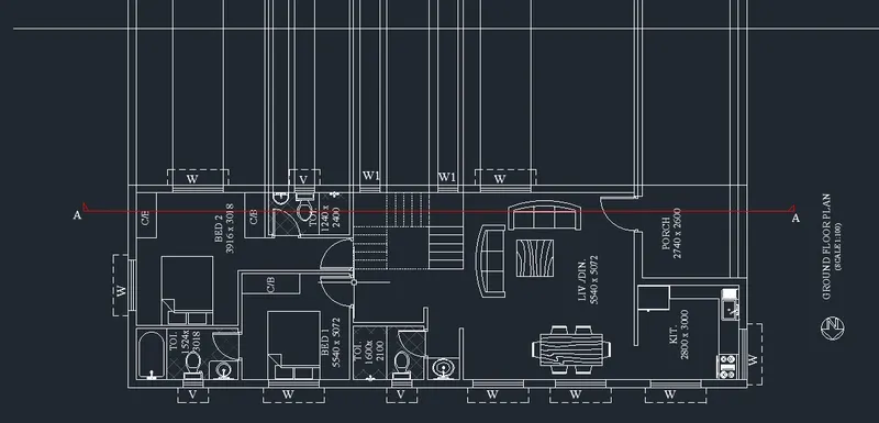
- Paste the elevation drawing on the left side of the rays so that the levels from the plinth, window sill, lintel, parapet etc can be used for the sectional elevation.
- Trim the unwanted lines to form the window in the section.
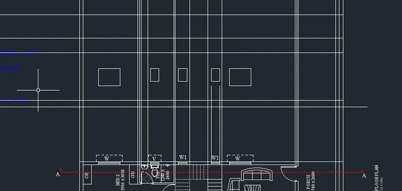
- Similarly by trimming the unwanted lines around various building projections the sectional elevation is formed.
- Draw the staircase section profile with the required riser and tread
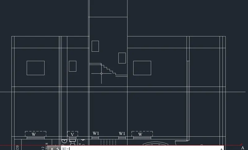
- Show the beams and walls in the section.
- Draw the railings for staircase and show as hidden by dashed lines.
- Show the sanitaryware in the bathroom section.
- Use hatch for the concrete works and brick wall in the section.
- Using Dimlinear show the various dimensions
- Show the level details using Leader.
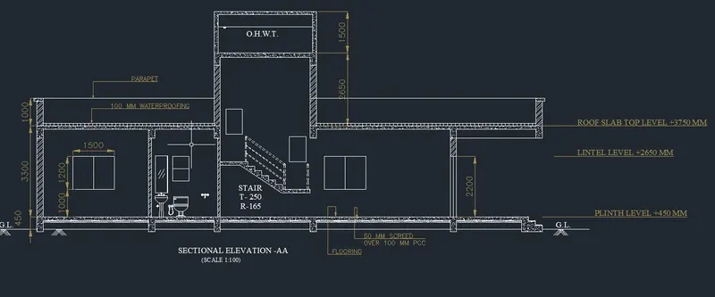
- Thus the drawing of Sectional Elevation of the Building is completed as shown in screen shot below.
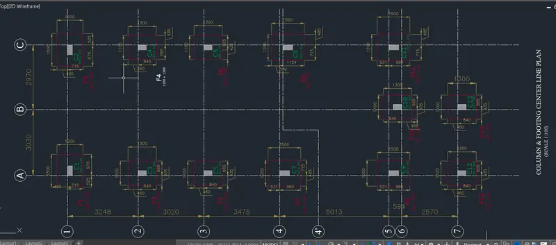
DRAWING FOOTING PLAN:
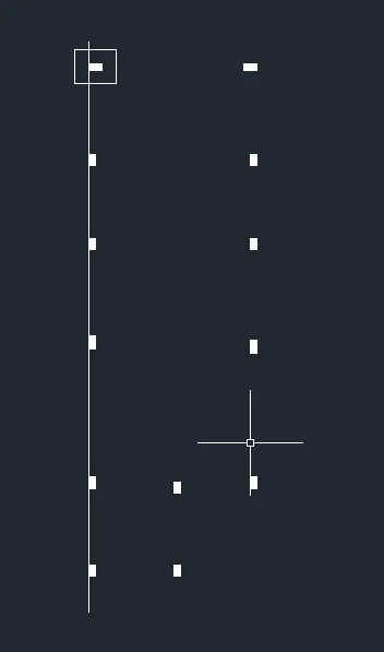
- Mark the column sizes and positions on the building plan.
- Select all the columns, Copy and paste the separately.
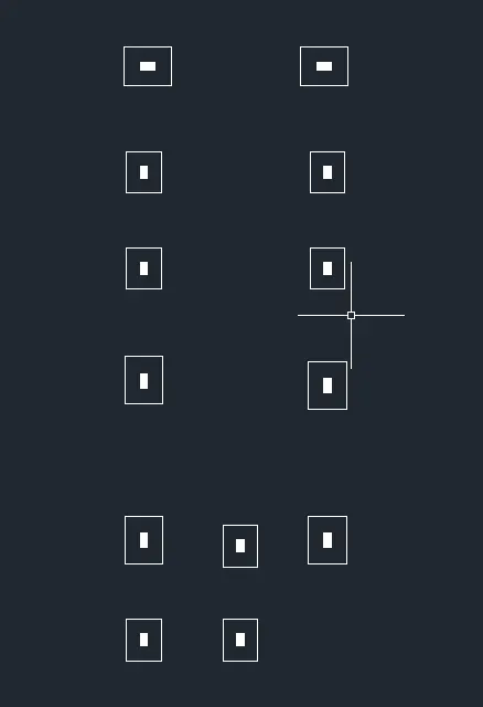
- Draw the footings sizes using the rectangle command.
- Using the geometric center of the rectangle paste on the geometric center of columns.
- Complete all the footings for the columns
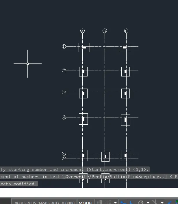
- Draw the flush line along the column edges and draw circle and using Mtext provide the grid names in the circle.
- Using the auto numbering in Express Tools the grids can be numbered
- Using Dimlinear show all the footing sizes, distance from the flush lines and the dimensions of the grid lines
- Using Mtext provide the column and footing nomenclature.
- Assign layers and colours to column and footing text and lines using layer properties.
- Provide the Drawing title and scale at bottom using MText.
- The Footing Layout of the building is completed as shown below.
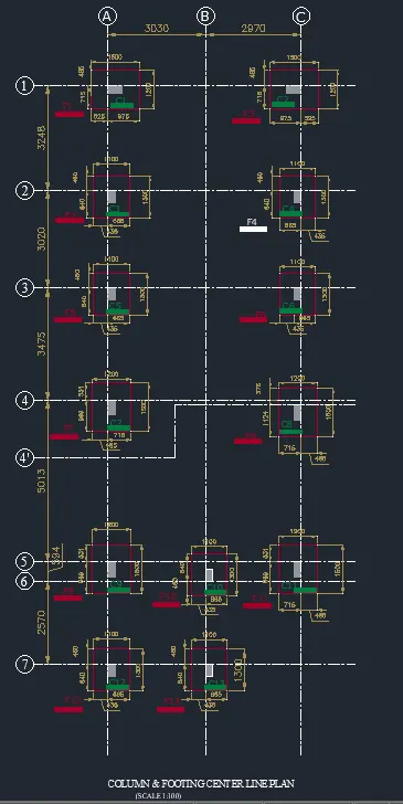
- Enlarged details are shown in the two screenshots below
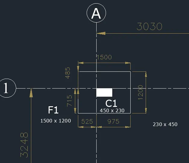
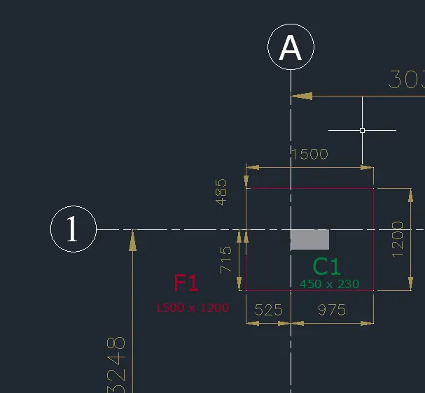
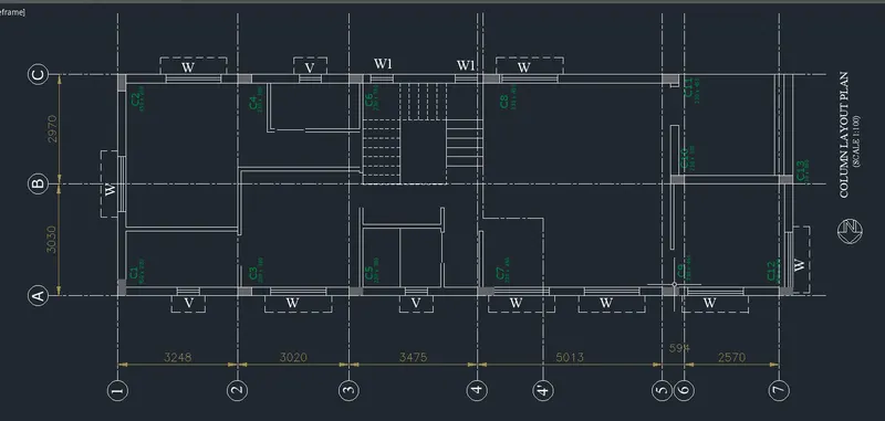
DRAWING OF COLUMN LAYOUT:
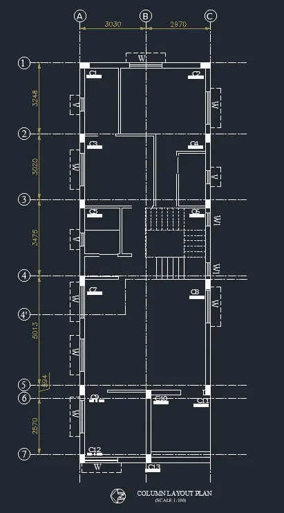
- Copy and paste the ground floor plan for drawing the column layout.
- Remove the furniture and other details.
- Mark the columns on the ground floor layout as per the beam positions below the walls
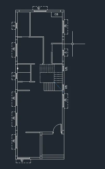
- Hatch the columns and provide the column nomenclature with sizes.
- Thus the Column Layout for the building is completed.
DRAWING GROUND BEAM LAYOUT:
- Using the ground floor layout drawing, draw the beam lines below the walls.
- Delete the wall lines
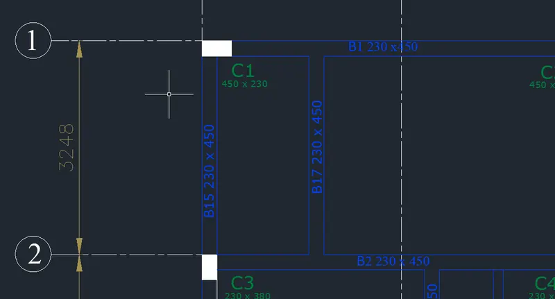
- Using MText write down the beam nomenclature in sequence along with beam sizes
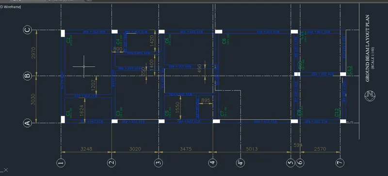
- Thus the Ground Beam layout drawing is completed as shown in the screenshot below.
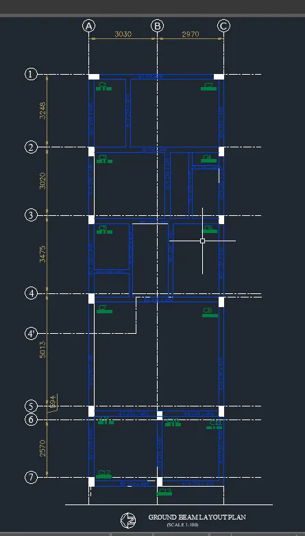
- The enlarged details of the Ground Beam Layout is shown in the screenshot below.
CONCLUSION:
- Thus the 2BHK residential building on ground floor with staircase block is designed and drawn showing all the details using various tools in AutoCad.
- The final completed drawing screenshots are attached below for reference
GROUND FLOOR PLAN:
SOUTH SIDE ELEVATION:
SECTIONAL ELEVATION THROUGH SECTION-AA
FOOTING LAYOUT DRAWING:
COLUMN LAYOUT DRAWING:
GROUND BEAM LAYOUT DRAWING: