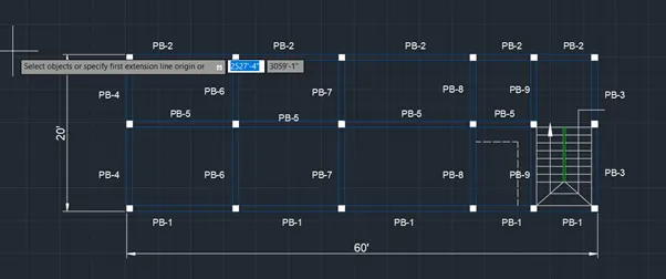
Project 1 _Creating an Architectural plan for the provided plot size and develop relevant basic structural drawings
Aim:-
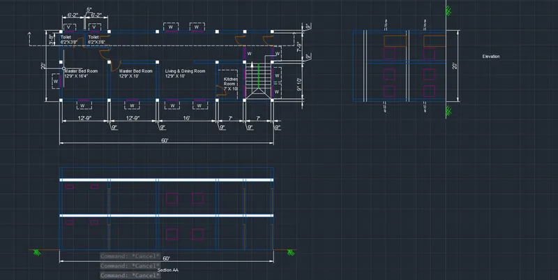
- To Draw the Floor Plan, Elevation and Section of Residential Buildings Using the Various Commands in Auto Cad
Procedure:-
- Give the Command of Units and Press Enter Select to Architectural and Inches press Enter
- Give the Command of XLine Enter
- Select the Horizontal in Command Bar Specify the Point
- Give the Command of XLine Enter
- Select the Vertical in Command Bar Specify the Point
- Give the Command of Offset Select the Object of Vertical Line Give the Offset Distance as 60’ and Press enter
- Give the Command of Offset Select the Object of Horizontal Line Give the Offset Distance as 20’ and Press enter
- Give the Command of Offset Select the Object Bottom of Horizontal Line Give the Offset Distance as 9” and Press enter
- Give the Command of Offset Select the Object Top of Horizontal Line Give the Offset Distance as 9” and Press enter
- Give the Command of Offset Select the Object Left Side of Vertical Line Give the Offset Distance as 9” and Press enter
- Give the Command of Offset Select the Previous offseted Line Give the Offset Distance as 9” and Press enter
- Give the Command of Offset Select the Previous offseted Line Give the Offset Distance as 6’2” and Press enter
- Give the Command of Offset Select the Previous offseted Line Give the Offset Distance as 9” and Press enter
- Give the Command of Offset Select the Previous offseted Line Give the Offset Distance as 6’2” and Press enter
- Give the Command of Offset Select the Previous offseted Line Give the Offset Distance as 9” and Press enter
- Give the Command of Offset Select the Previous offseted Line Give the Offset Distance as 12’9” and Press enter
- Give the Command of Offset Select the Previous offseted Line Give the Offset Distance as 9” and Press enter
- Give the Command of Offset Select the Previous offseted Line Give the Offset Distance as 7’ and Press enter
- Give the Command of Offset Select the Previous offseted Line Give the Offset Distance as 9” and Press enter
- Give the Command of Offset Select the Previous offseted Line Give the Offset Distance as 7’ and Press enter
- Give the Command of Offset Select the Previous offseted Line Give the Offset Distance as 9” and Press enter
- Give the Command of Offset Select the Object Bottom of Horizontal Line Give the Offset Distance as 10’ and Press enter
- Give the Command of Offset Select the Previous offseted Line Give the Offset Distance as 9” and Press enter
- Give the Command of Offset Select the Previous offseted Line Give the Offset Distance as 7’ 9”and Press enter
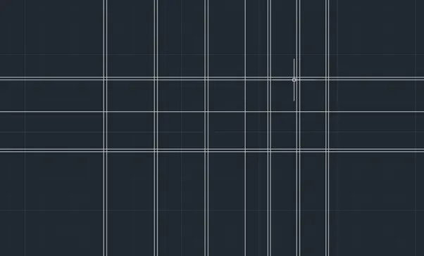
-
Give the Command of Trim in Command Bar Trim Unnecessary Lines
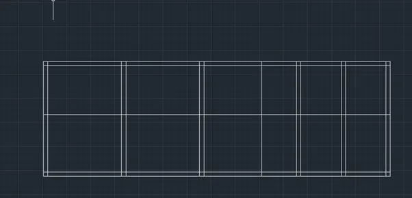
- Give the Command of Fillet its used Wherever its Required
- Give the Command of Trim , trim the Lines Wherever its Required
- Select the Layers From the Ribbon tab Create a New a Layer as Per Requirements
- Select the Colour as per our Own Choice Press Enter
- Draw a Door Panel as per Desirable Size and Shape
- Place its wherever its Required Press Esc.,
- Draw a Staircases as requirement
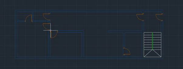
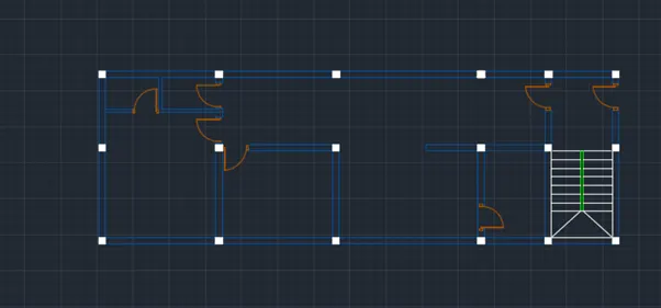
- Select the Layers From the Ribbon tab Create a New a Layer as Columns Press enter
- Select the Colour as per our Own Choice Press Enter
- Draw a Column By Using Give the Command of Rec in Command Bar
- Give the Command of Hatch and Select the hatch Type and Specify the Point and Press Enter
- Specify the Starting Point and Select the Dimensions from the Command Bar and Give the Length as 9” and Breadth as 9” Press enter
- Give the Command of Copy and Press Enter Select the object and specify the staring Point and Place its Wherever its required
- Press Esc.,
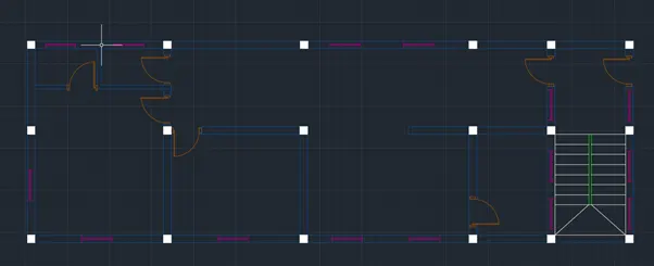
- Select the Layers From the Ribbon tab Create a New a Layer as Windows Press enter
- Select the Colour as per our Own Choice Press Enter
- Give the Command of L and Press Enter and Specify the Staring Point and Move the Cursor to X Direction and Give the Length as 9”
- Dynamic input on and Keep Ortho and Snap On and Select the Mid Point and Give the Window Length and Press enter
- Give the command of Mirror and Select the Object and Specify the Point and Mirroring the as Per Requirement
- Press Esc.,
- Give the Command of Copy and Select the Object and place its where its required
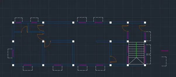
- Select the Layers From the Ribbon tab Create a New a Layer as Sun Shades Press enter
- Select the Colour as per our Own Choice Press Enter
- Select the Line type and Press Enter
- Draw a Sunshade as per Specifications
- Project the Lines From the Floor Plan as per requirement for Section Press Esc.,
- Give the Command of XLine Press Enter
- Specify the Horizontal From the Command Bar Press Enter
- Specify the Point and Press Enter
- Give the Command of Offset and Select the Object and Give the Offset Length as Floor Height Suitability
- Give the Command of Offset Select the Previous offseted Line Give the Offset Distance as Per Slab Thickness
- Press Enter
- Give the Command of Offset and Select the Object and Give the Offset Length as Floor Height Suitability
- Give the Command of Offset Select the Previous offseted Line Give the Offset Distance as Per Slab Thickness
- Press Enter
- Give the Command of Offset and Select the Object and Give the Offset Length as 3’ For Parapet Wall
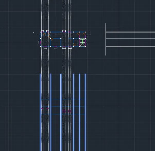
- Give the Command of Trim, Trim the Unnecessary Lines Press Enter
- Select the objects walls Set in to Walls Layers
- Same as Suitability to Compition of Process
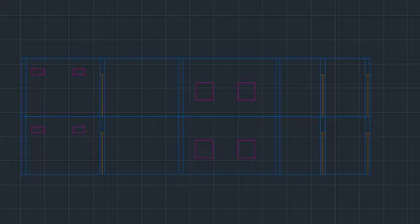
- Give the Command of Hatch and Press Enter
- Specify the Point and Press Enter
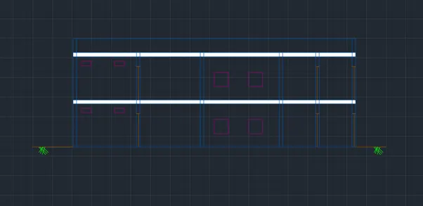
- Project the lines along Horizontal Direction and Press Enter
- Give the Commandof Xline Press Enter
- Specify the Point and Select Vertical From the Coammand Bar Press Enter
- Pqalce its Suitability
- Give the Coammand of Trim its Used to Trim Unnecessary Lines
- Give the Offset Command and Select the Objects and Give the Offset Ditances as Per Requirement and Suitability
- Press Enter
- Slect the Objects and Set the Layers into Required to it
- Press enter
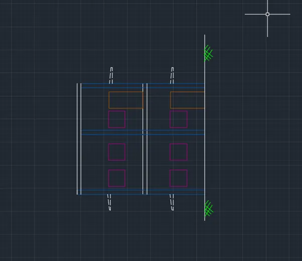
Result:-
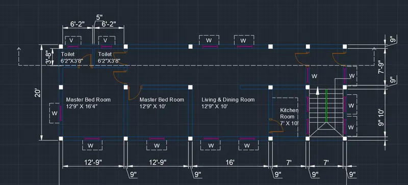
Aim:-
To Draw the Column, Beam, Footing Plan by Using Auto Cad
Procedure:-
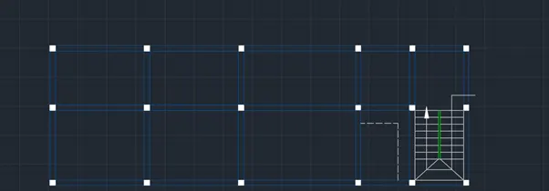
- Select the Floor Plan and Trim Unwanted objects and Press Enter
- Give the Comamnd of Xl line Press Enter
- Select the Horizontal from the Command Bar and Specify the Center Point of Column and Press ENter
- Repeat the Procedure Untill Complition of Lines
- Press Esc.,
- Give the Comamnd of Xl line Press Enter
- Select the Vertical from the Command Bar and Specify the Center Point of Column and Press ENter
- Repeat the Procedure Untill Complition of Lines
- Press Esc.,
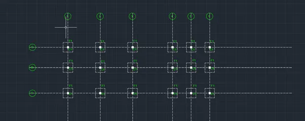
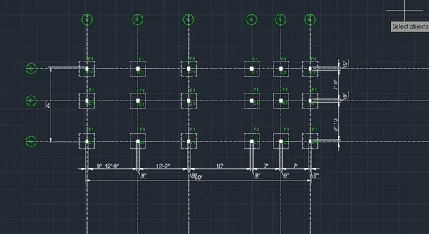
- Create a Layers as Footing From the ribbon Tab Press enter
- Select the Line type as Dot Line andPress Enter
- Give the Command of rec and Press enter
- Specify the Starting Point and Selct the Dimensions and Give the length and Breadth as (4'x4') and Press enter
- Give the Command of Copy Select the Object and Press enter
- Specify the Cneter Point of the Rectangle Place its Center Point of the Columns in All Press Enter
- Copy the Floor Plan Press Enter
- Delete the Unwanted Objects and Press Enter
- Give the Command of Ex and Press enter
- Select the Object to Extend
- Give the Command of trim to trim Unwanted Line press enter
- Select the Single Line Text From the Ribbon tab to anntative bar and Press enter
- Give the text as per Sutability Press enter
Result:-