Project 1 _Creating an Architectural plan for the provided plot size and develop relevant basic structural drawings
AIM
To design and draft a layout of a residential building with plot size 60'*20'(18.3m*6m) and orientation- facing east
INTRODUCTION
The residentia; building to be drawn with plot dimensions 60'*20' . The G+1floor residential building is dessigned with stairs inside the house . The plot is east facing .The building is designed with following rooms
- 4 Bedrooms(2 in ground floor and 2 in first floor)
- 4 toilet(2 in ground floor and 2 in first floor)
- 2 living room(1 in ground floor and 1in first floor)
- 1kitchen cum dinning
- staircase to first floor
Walls- Thickness of the external wall is taken as 9" and internal wall is taken as 4.5"
Column and beam-column size are of 9"*12"
all beams are of size 9"*12"
DOORS-BEDROOMS 3'*7'
MAIN DOOR -4'*7'
TOILETS -2'*7'
WINDOWS-Bedrooms-W1-3'*4'
W2-4'*4'
toilets W3-2'*3'
STAIRCASE-riser-6"
tread-1'
COMMANDS USED
- Unit command
- Limit command
- Line command
- Offset command
- Trim command
- Layer command
- Hatch command
- Rectangle command
- Dimlinear command
- Mtext command
- Dtext command
- Dimstyle command
- Move command
- Copy command
- Divide command
- Object snap command
- Extend command
- Fillet command
PROCEDURE
STEP 1
- Open a new file
- In the command line type units , select the units and also set the precision
- In the command line type 'LIMITS' and specify the limits at lower left corner and upper right corner as
- Then zoom all
STEP 2
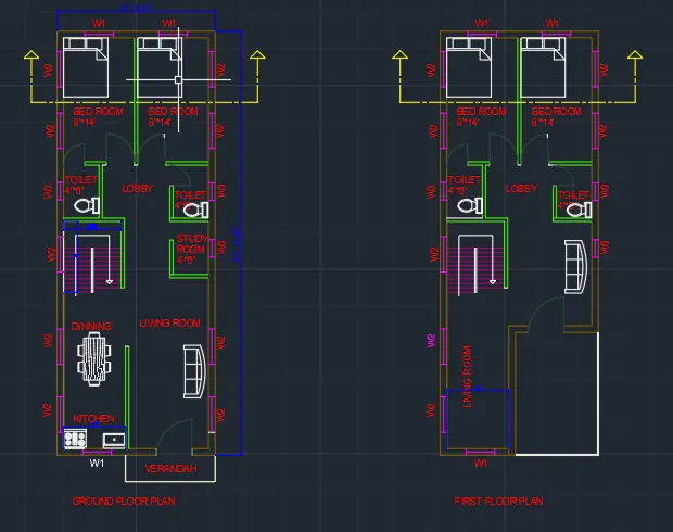
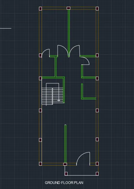
- First to draw the ground floor plan
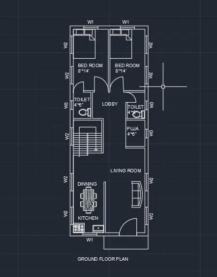
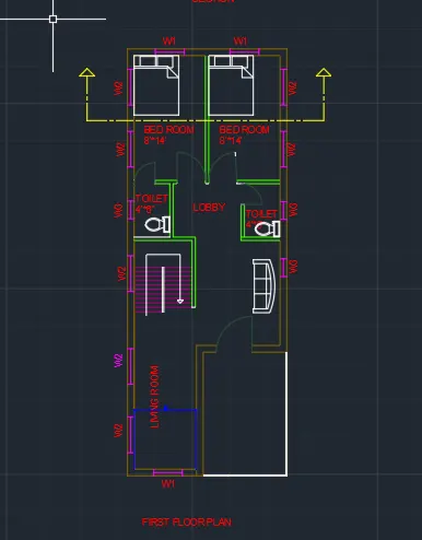
- Using line offset and trim and extend command draw two bedrooms of size 8'*14'and toilets of size 4'*6'
- then drawing staircase room of 6'-6"*8'
- and study room of 4'*6"
- from stairroom offset17'-8.04"
- offset from side 7'
- by this way plan is made with wall thickness outside as 9" and inside 4.5"
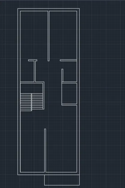
- then doors and window openings are made according to the standard size
- using mtext command texts are written
- using dimlinear dimensions are marked
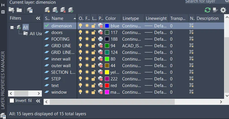
- Providing the layer property to the plan
- and cutting the section line
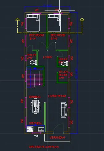
- Copying the ground floor plan and making the necessary changes , this way we are creating the second floor plan
STEP 3
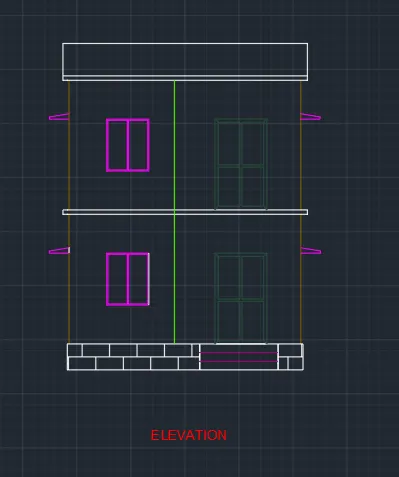
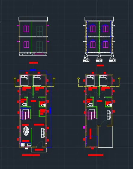
- Next drawing elevation by projecting lines from the plan
- offset offset for plinth by 2'
- then providing the wall height as 10'
- drawing the chajjas
- drawing doors and windows that we can through the front view
- same way drawing first floor also
- prapret wall is provide at the height of 2'-6"
- using hatch command hatch is provide for the plinth
STEP 4
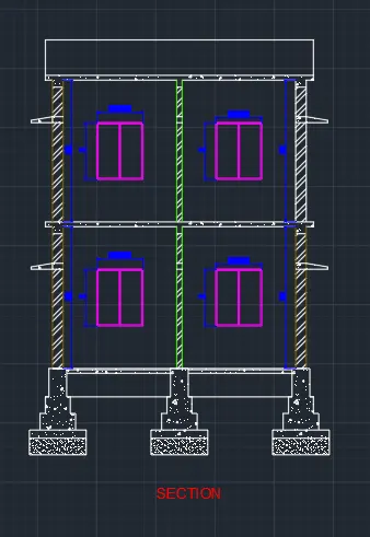
- next drawing the section by projecting the lines from plan for section lines
- project lines from the elevation for the height
- trim off the unwanted lines
- using hatch command hatch the walls with the bricks and foundation with the concrete hatch
- place the windows inrespective position
STEP 5
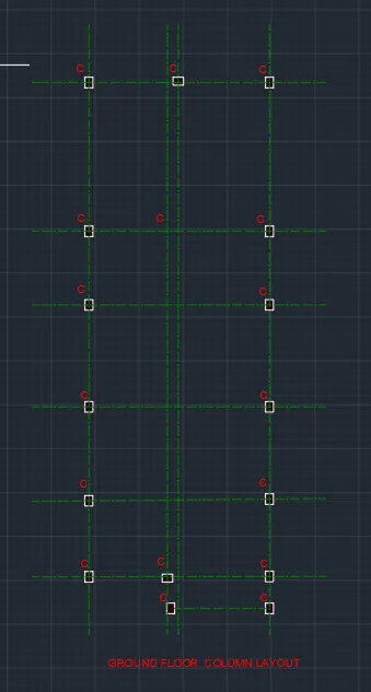
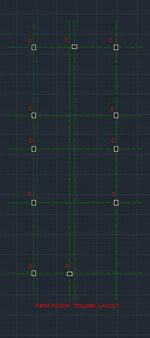
- Drawing column layout
- draw column in the plan where ever required
- using the trim command trim everthing except the outerline and the colums
- create a layer for grid lines
- load the layer ,make it as current layer
- using line command draw the grid line from center to center
- then offset the outerline by5' and delete the outer line
- then extend the grid line to the offseted line
- delete the offseted line
- same way first floor columns layout is drawn
STEP 5
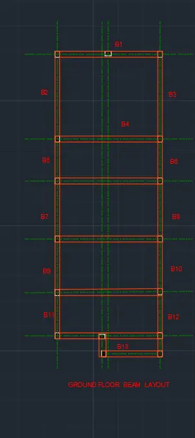
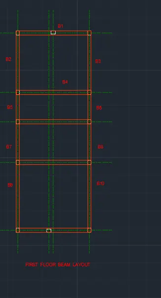
- drawing beam layout
- change the current layer to beam
- beams are drawn with the dimension 9"12"
STEP 6
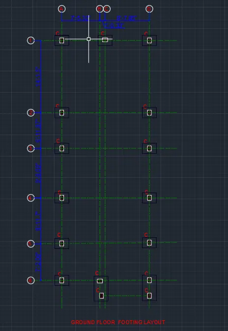
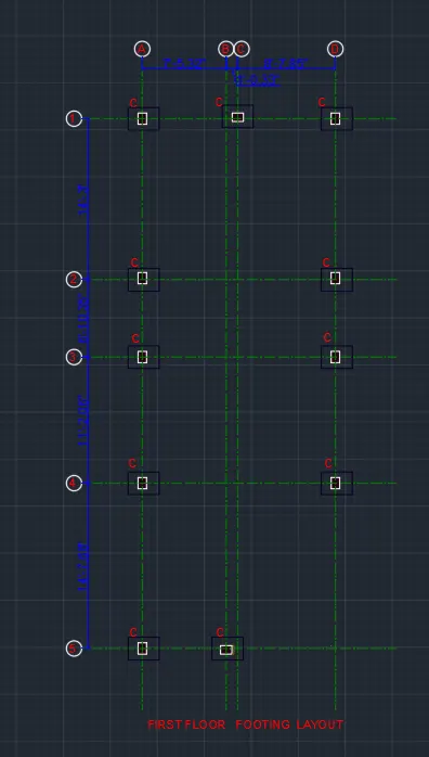
- copy the column layout
- change the current layer to footing
- dimension of the all footings drawn are 3'-4"*3'-4"
- using dimlinear mark the distance blw the footings
RESULT
Using vastushastra , with the given plot size 60'*20' drawn a east facing residential building with G+1 floor
PLAN, ELEVATION AND SECTION
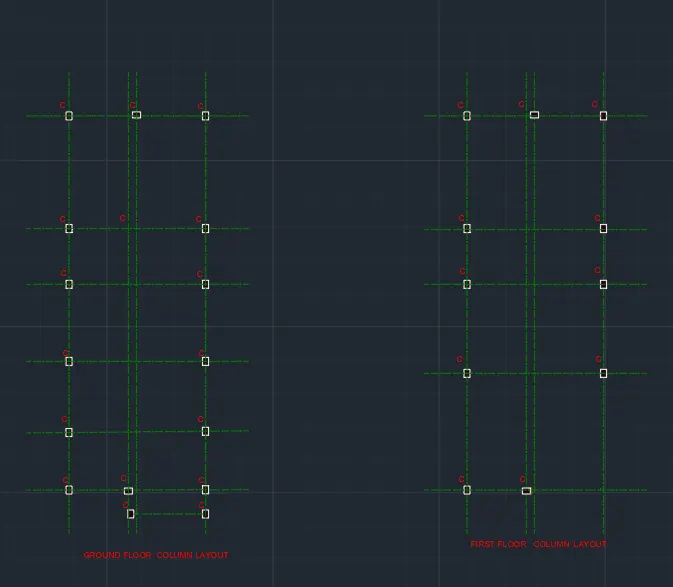
COLUMN LAYOUT
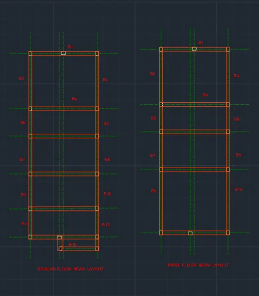
BEAM LAYOUT
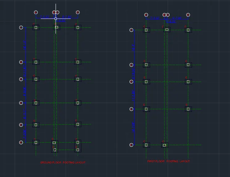
FOOTING LAYOUT