Project 1 _Creating an Architectural plan for the provided plot size and develop relevant basic structural drawings
AIM: To design and draft a layout of a residential building in a given plot size of 60’x20’(18.3m x6m). With orientation east side.
ASSUMPTION:
Exterior wall thickness= 9"
Interior wall thickness= 4"
Door:
- D1= 4'-11" X 6'-10"
- D2= 3'-3" X 6'-10"
- D3= 3'-0" X 6'-10"
Window:
- W1=4'-11" x 3'-3"
- W2=3'-3" x 3'-3"
- W3=3'-2" x 3'-3"
- V=2'-0" x 2'-0"
PROCEDURE:
- Open cad application in the pc and set all the limits required.
- Set the units as required for drawing. Set units in Engineering and scale in Inches.
- Keep ortho on for easily drawing lines in right angles.
- Start the drawing with the mentioned plot size and orientation.
- Select construction line and draw the outer line of the wall.
- Select offset command and carry on the drawing as given in drawing.
- The each house is different in size, shape and dimensions.
- After selecting the house take wall thickness of outer as 9" and inner as 4" where ever required.
- So the respective wall thickness wherever shown in plan.
- After completing all the walls offset.
- Select trim command and trim off the extra lines and make a good corner.
- While trimming the lines watch the given plan again and again for accurate drawing.
- Now do the staircase part using given size and show the tread with 9".
- Next show the doors wherever needed with respective sizes.
- Select the size with respect to the ease of use.
- Use line command to draw the lines of door.
- Using trim command remove the unwanted lines.
- Once the doors are done now go with windows.
- Select the window size with respect to room size and utility.
- Keep the window in the centre of each room walls.
- Same as door use line command and draw the either sides of window.
- Next draw two lines so that it indicates the thickness of window.
- Now place the columns as shown and in the mentioned orientation.
- The drawing part of plan is now completed now start with the naming.
- Use text command to write the names.
- Do naming of every door, window and room using the text command.
- While naming set the text and arrow size in a way that they are clearly visible.
- Show the dimensions wherever the room is not in square or rectangle.
- This is also done where two rooms are combined.
- Hatch the all the columns using concrete hatch.
- Now draw the Chajja in all the sides of building of 600mm width.
- Keep some bearing in the either side of the window.
- Create a layer of dotted lines for showing Chajja.
- Make a layer of dotted lines for section lines.
- After completing all the drawing parts, now draw line with x axis.
- Now start with the cross section part.
- Use construction line to draw the vertical lines of wall thickness that are coming in the section line.
- Draw one horizontal line and take it as base.
- Using offset command first draw all the floor height and show the thickness of slab.
- Draw the beams wherever required.
- Trim off the excess wall lines.
- Not show the doors, the doors are ended in lintel bottom level.
- After the doors show window with respective sizes and width.
- Draw the parapet wall and provide a waterproofing coat in slab.
- The footing cross section is also provided.
- Do the required naming and required dimensions like total height and floor to floor height etc.
- Now start with the section BB drawing, the section line through the Y axis.
- Copy the plan and rotate it in the arrow direction.
- Now select construction line and draw the wall thickness.
- Take the horizontal line and make it as base.
- Do carry the same steps as in section AA.
- Here there is a balcony where the railings have to be done.
- Use polyline and draw a designed railing in verandah.
- Check the distance and make it fix there.
- In the other side we have also to show the railings.
- Draw the lintel with Chajja wherever it has been cutted.
- Before starting with dimensioning go to dimension style and change the primary unit as engineering and set the precision.
- When the section drawings are completed then start with the naming and dimensioning work.
- The naming can be copied using copy command and pasted of previous drawing.
- Select the size of text and arrows so that are clearly visible and easily recognized.
- By following the above steps we can complete the whole Plan and Sections as required.
- Mark the North direction using the arrow symbol in the plan.
- Use a 45degree small lines to show the part in window where glass are used.
- The outer size or dimension of the building should be accurate as mentioned above in question.
RESULT:
1) Architectural Drawing:
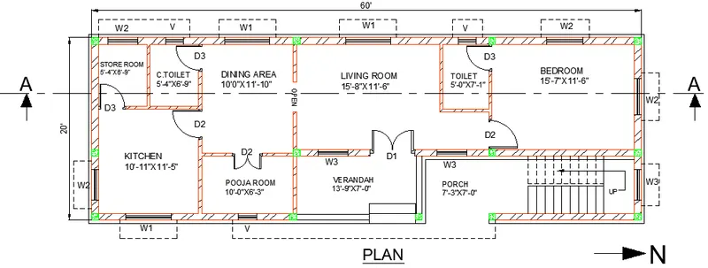
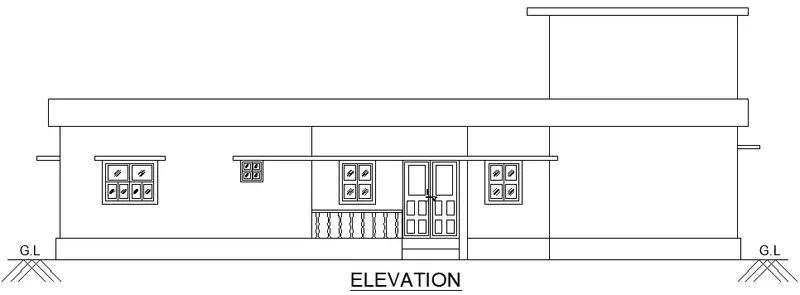
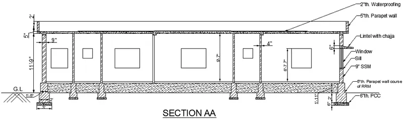
2) Structural Drawing:
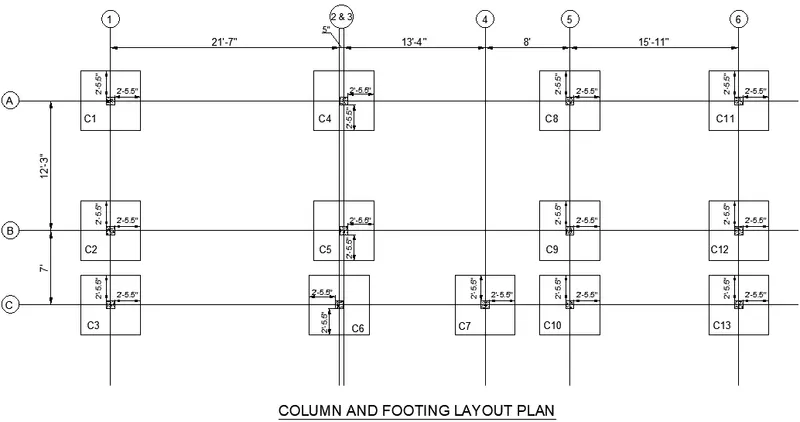
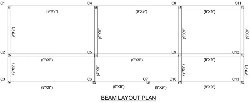
NOTE: The pdf has been attached below of all the above drawings.