Project 1 _Creating an Architectural plan for the provided plot size and develop relevant basic structural drawings
1Q]
AIM: -
Design and draft a Residential Building
Plot size: 60’ x 20’
Facing EAST
Create Architectural Drawings- Floor plan, Sectional Plans and Elevations
Create Structural Drawings – Column, Footing and Beam
PROCEDURE: -
Set the units to ENGINEERING using UNITS command
Set the lower limit and upper limit of the screen using LIMITS command
Lower limit: 0’, 0’
Upper limit: 100’, 100’
Type Zoom
Select all and press Enter
Type XLINE
Select Vert option and draw a vertical line
Type XLINE
Select Hor option and draw a horizontal line.
The two lines intersects and this point is the starting point.
Start from left and go to right.
Select LAYER properties dialogue box
Create New Layers
Select different COLOUR to each layer created.
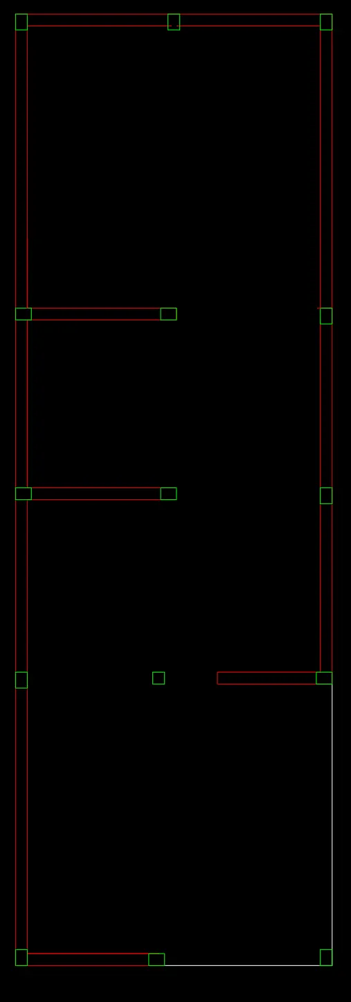
Locate Columns
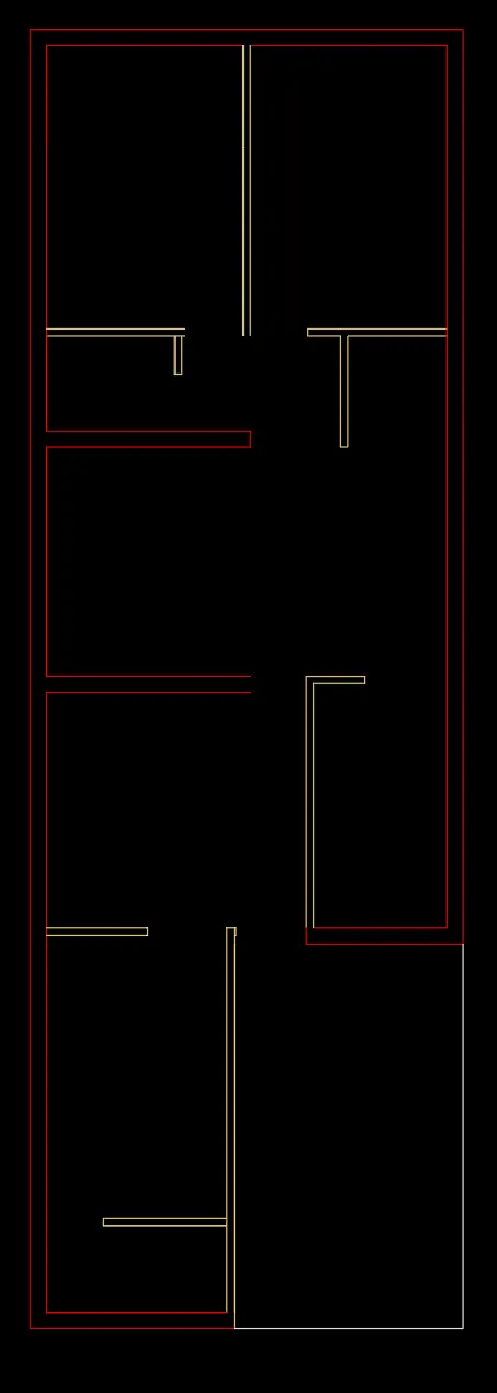
Choose Line command to draw rooms as per vaastu.
Consider External wall thickness as 9” inches and internal wall thickness as 4” inches.
Select the OFFSET command for wall thickness
Use FILLET command for trimming wall corners
Select LAYER properties dialogue box
Create New Layers
Select different COLOUR to each layer created.
Choose Line command to draw staircase.
Draw staircase with size of Tread- 11” inches
Assume Doors and Window sizes
W1= 6’ x 4’
W2= 4’ x 4
V= 2’ x 2’
D1= 3’-3”x 6’-8”
D2= 3’-0” x 6’-8”
D3= 2’-6”x 6’-8”
Draw Doors and Windows
Draw shades to these windows.
Change Linetype of the shades to ISO DASH SPACE.
Change Line Scale if required.
Select ANNONTATE in Ribbon
Under TEXT dialogue box
Choose Multiline Text tool
Using MTEXT label the details
Select command: ‘_STYLE
Create new style with Font name - Arial and Font Style – Regular
Set current.
Select LAYER properties dialogue box
Create New Layers
Select different COLOUR to each layer created.
Set the TEXT as Current Layer
Write Text of all rooms.
In the Text Editor, use SPELL CHECK tool for any spell checks
Select ANNONTATE in Ribbon
Select LEADERS PALETTE
Choose MULTILEADER STYLE MANAGER
Create new style
Modify the Leader format, Leader structure, Content
And Set current.
Select LAYER properties dialogue box
Create New Layers
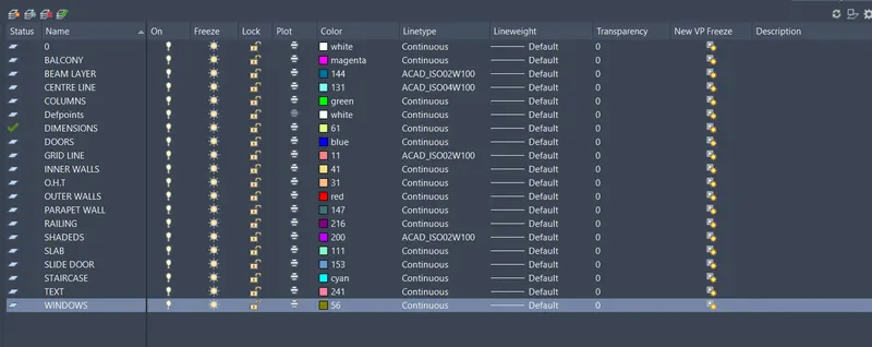
Set the Dimensions as Current Layer
Provide Dimensions to each floor and wall thickness
Use LEADERS command wherever required.
Select ANNONTATE in Ribbon
Under DIMENSION dialogue box
Select DIMLINEAR command to mark column dimensions, and then
Select DIMCONTINUE command to mark the distances
Select DIMBASELINE command to mark the distance from base to the respective object.
Use DIMBREAK command wherever dimension lines intersect.
RESULT: -
By using DRAWING tools, MODIFY tools, ANNOTATE tools and LAYER properties we generated FLOOR PLANS.
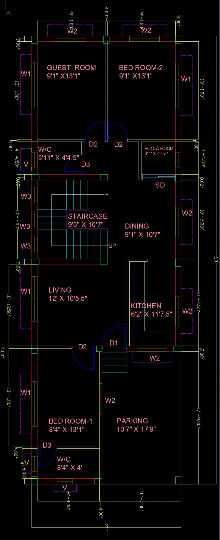
Repeat the above mentioned steps to draw First Floor Plan
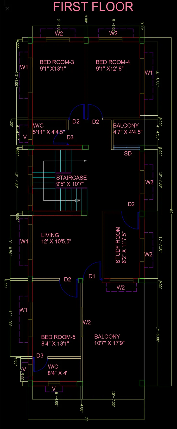
Draw Section lines on the Plan to develop Sectional Drawings.
Two Sections
1) Section A-A
2) Section B-B
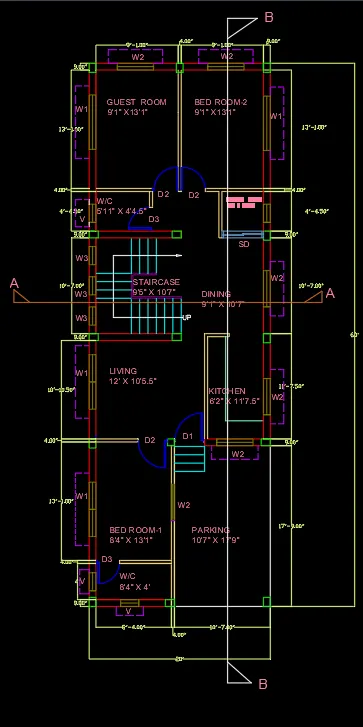
2]
- SECTIONAL DRAWINGS
AIM: -
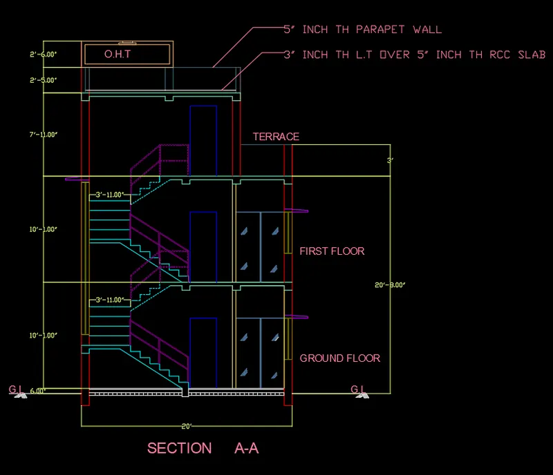
Create the section A-A
Use proper dimension techniques and dimension styles
Use Layers.
PROCEDURE: -
Select command: XLINE
Select vertical option
Turn on the OBJECT SNAP
Wherever the Section cuts project the lines of objects from the floor plan using XLINE command.
Draw a Horizontal Line. This is G.L
Provide Elevation Height as 10'-1" units
Using OFFSET tool with offset distance as 10'-1" draw roof slab
Using OFFSET tool with offset distance as 5" draw roof slab thickness.
Provide slab thickness as 5" INCH
After drawing, use MODIFY tools
Use TRIM command to trim the extended lines.
Use EXTEND command to the extend the required lines.
Use OFFSET command to provide thickness to slabs shades etc.
Use FILLET command to trim the corners.
After finishing the G.L floor details.
Provide height of 10'-1" units for 1st floor
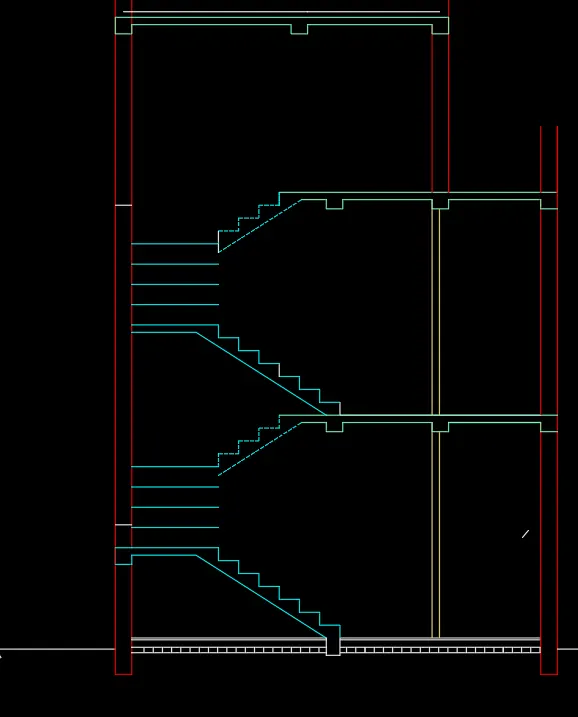
Project Door and columns from floor plan.
Using XLINE and OBJECT SNAP project DOORS of SD and D2 of each room from floor plan.
Provide height to DOORS
Select LAYER properties dialogue box
Create New Layers : RAILING, PARAPET WALL
Select different COLOUR to each layer created.
Select LINE tool to draw:
Provide RAILING to STAIRS
Draw PARAPET WALL
Project walls from plan and provide height and thickness to walls.
Draw windows to the outer wall and provide sun shades on both sides of outer walls
Repeat the same procedure of 1st flOOR
Use COPY command to draw the 1ST FLOOR
Provide 4' units height of parapet wall on top of 1ST floor
Use OFFSET command to provide thickness to O.H.T
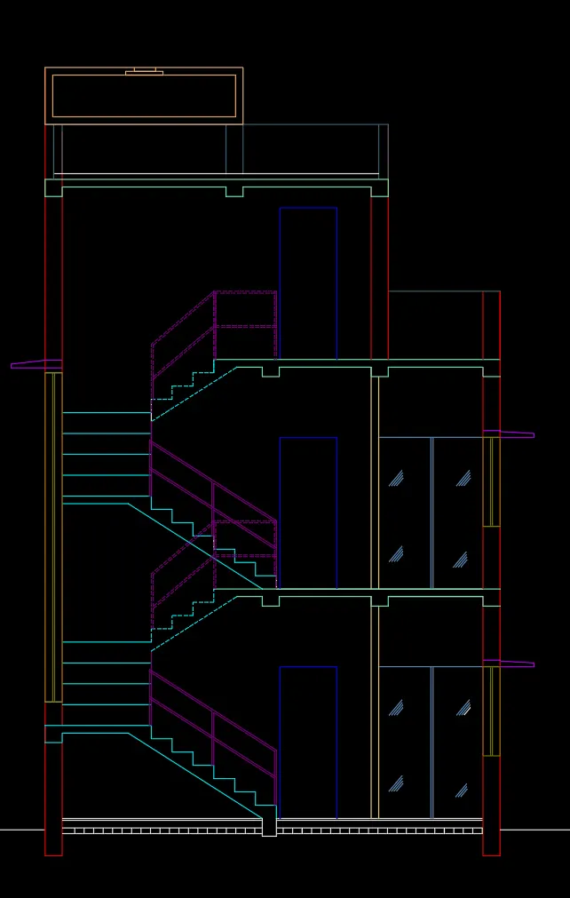
Select ANNONTATE in Ribbon
Under TEXT dialogue box
Choose Multiline Text tool
Using MTEXT label the details
Select command: ‘_STYLE
Create new style with Font name - Arial and Font Style – Regular
Set current.
Write Text of all floors.
In the Text Editor, use SPELL CHECK tool for any spell checks
Select ANNONTATE in Ribbon
Select LEADERS PALETTE
Choose MULTILEADER STYLE MANAGER
Create new style
Modify the Leader format, Leader structure, Content
And Set current.
Use LEADERS command wherever required.
Select ANNONTATE in Ribbon
Under DIMENSION dialogue box
Select DIMLINEAR command to mark dimensions, and then
Select DIMCONTINUE command to mark the distances.
Select DIMBASELINE command to mark the distance from base to the respective object.
Use DIMBREAK command wherever dimension lines intersect.
Set the Dimensions as Current Layer
Provide Dimensions to each floor and wall thickness.
RESULT:-
By using DRAWING tools, MODIFY tools, ANNOTATE tools and LAYER properties and by generating projections from Floor plan we generated SECTIONAL DRAWING A-A
SECTION B-B
AIM: -
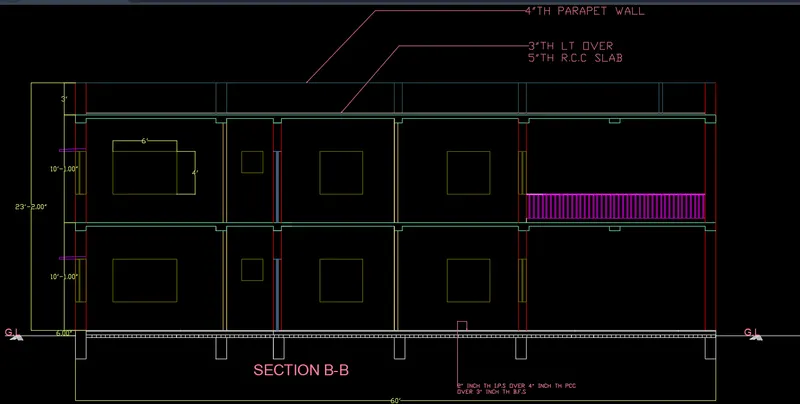
Create the section B-B
Use proper dimension techniques and dimension styles
Use Layers.
PROCEDURE: -
Select command: XLINE
Select vertical option
Turn on the OBJECT SNAP
Wherever the Section cuts project the lines of objects from the floor plan using XLINE command.
Draw a Horizontal Line. This is G.L
Type XLINE
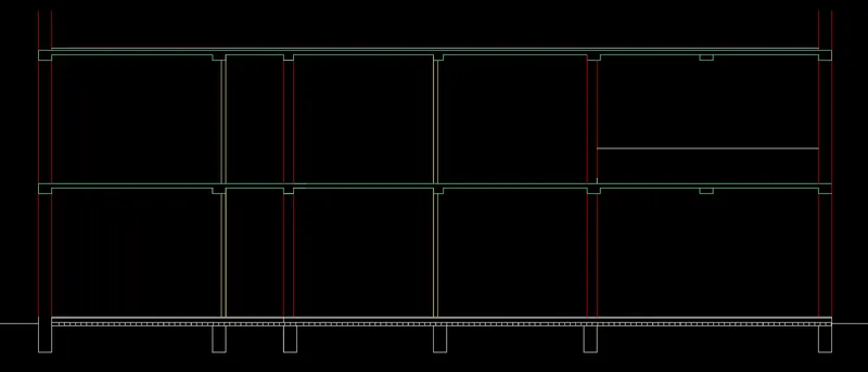
Project Floor plan details to draw Section B-B
Provide Elevation Height as 10'-1" units
Using OFFSET tool with offset distance as 10'-1" draw roof slab
Using OFFSET tool with offset distance as 5" draw roof slab thickness.
Provide slab thickness as 5" INCH
After drawing, use MODIFY tools
Use TRIM command to trim the extended lines.
Use EXTEND command to the extend the required lines.
Use OFFSET command to provide thickness to slabs shades etc.
Use FILLET command to trim the corners.
After finishing the G.L floor details.
Provide height of 10'-1" units for 1st floor
Repeat the same procedure of 1st flOOR
Use COPY command to draw the 1ST FLOOR
Project Door and columns from floor plan.
Using XLINE and OBJECT SNAP project windows of each room from floor plan.
Provide height to windows
Project walls from plan and provide height and thickness to walls.
Provide 4' units height of parapet wall on top of 1ST floor
Select LAYER properties dialogue box
Create New Layers
Select different COLOUR to each layer created.
Select ANNONTATE in Ribbon
Under TEXT dialogue box
Choose Multiline Text tool
Using MTEXT label the details
In the Text Editor, use SPELL CHECK tool for any spell checks
Select ANNONTATE in Ribbon
Use LEADERS command wherever required.
Select ANNONTATE in Ribbon
Under DIMENSION dialogue box
Select DIMLINEAR command to mark dimensions, and then
Select DIMCONTINUE command to continue the distances .
Select DIMBASELINE command to mark the distance from base to the respective object.
Use DIMBREAK command wherever dimension lines intersect.
RESULT: -
By projecting the objects from Floor plan we generated the Secction B-B
3]
- ELEVATION
AIM: -
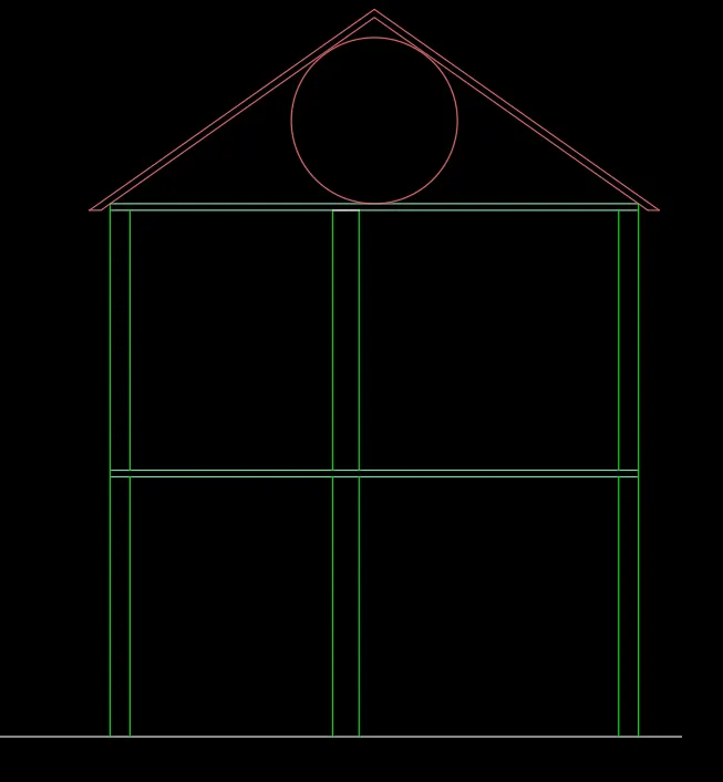
Create the FRONT ELEVATION
Use proper dimension techniques and dimension styles
Use Layers.
PROCEDURE: -
Select command: XLINE
Select vertical option
Turn on the OBJECT SNAP
Wherever the Section cuts project the lines of objects from the floor plan using XLINE command.
Draw a Horizontal Line. This is G.L
Type XLINE
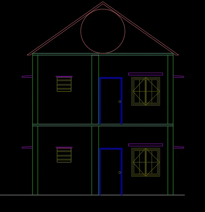
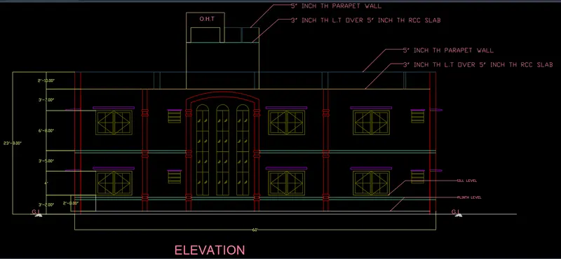
Project Floor plan details to draw Front Elevation.
Provide Elevation Height as 10'-1" units for each floor
Using OFFSET tool with offset distance as 10'-1" draw roof slab
Using OFFSET tool with offset distance as 5" to draw shades
After drawing, use MODIFY tools
Use TRIM command to trim the extended lines.
Draw windows to the outer wall and provide sun shades on both sides of outer walls
Draw the Steps with Rise-7" units and Tread- 11" units.
Project Door from floor plan.
Select ANNONTATE in Ribbon
Under TEXT dialogue box
Choose Multiline Text tool
Using MTEXT label the details
Select command: ‘_STYLE
Create new style with Font name - Arial and Font Style – Regular
Set current.
Write Text of all floors.
Select ANNONTATE in Ribbon
Select LEADERS PALETTE
Use LEADERS command wherever required.
Select ANNONTATE in Ribbon
Under DIMENSION dialogue box
Select DIMLINEAR command to mark dimensions.
Select DIMCONTINUE command to mark the distances
Select DIMBASELINE command to mark the distance from base to the respective object.
Use DIMBREAK command wherever dimension lines intersect.
RESULT: -
- SIDE ELEVATION
AIM: -
Create the SIDE ELEVATION
Use proper dimension techniques and dimension styles
Use Layers.
PROCEDURE: -
Select command: XLINE
Select vertical option
Turn on the OBJECT SNAP
Wherever the Section cuts project the lines of objects from the floor plan using XLINE command.
Draw a Horizontal Line. This is G.L
Type XLINE
Project Floor plan details to draw Front Elevation.
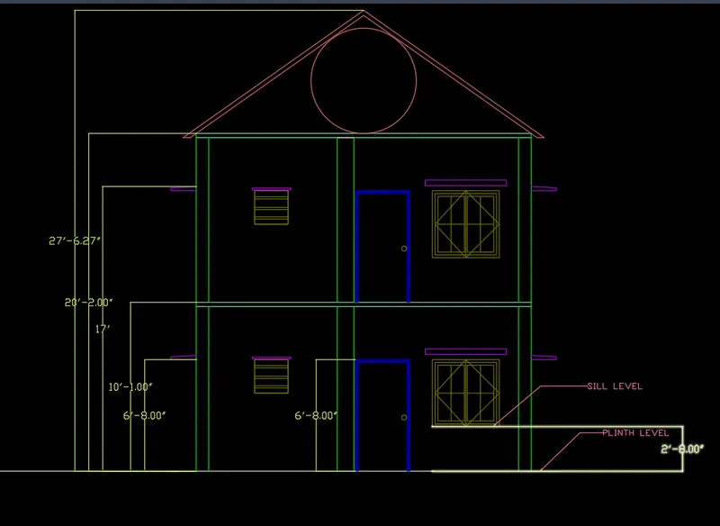
Provide Elevation Height as 10'-1" units for each floor
Using OFFSET tool with offset distance as 10'-1" draw roof slab
Using OFFSET tool with offset distance as 5" to draw shades
After drawing, use MODIFY tools
Use TRIM command to trim the extended lines.
Draw windows to the outer wall and provide sun shades on both sides of outer walls
Select ANNONTATE in Ribbon
Under TEXT dialogue box
Choose Multiline Text tool
Using MTEXT label the details
Write Text of all floors.
Select ANNONTATE in Ribbon
Select LEADERS PALETTE
Use LEADERS command wherever required.
Select ANNONTATE in Ribbon
Under DIMENSION dialogue box
Select DIMLINEAR command to mark dimensions.
Select DIMCONTINUE command to mark the distances
Select DIMBASELINE command to mark the distance from base to the respective object.
RESULT: -
By projecting the floor details we generated Side Elevation showing with dimensions and details.
STRUCTURAL DRAWINGS.
1]COLUMN LAYOUT
AIM: -
Create the Column LAYOUT
Use proper dimension techniques and dimension styles
Use Layers.
PROCEDURE: -
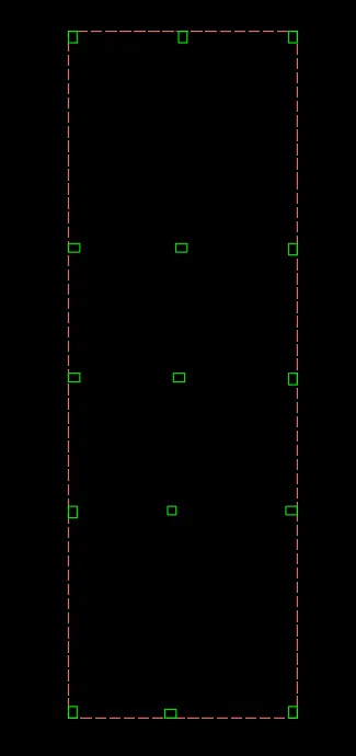
Hide all the layers in the Floor Plan
Turn on the Layers of Columns
All columns are visible.

Select LAYER properties dialogue box
Create New Layers: GRIDLINES
Line type: ISO DASH
Select different COLOUR to each layer created.
Draw Gridlines arround the columns.
Select LAYER properties dialogue box
Create New Layers: CentreLines
Linetype :ISO LONG-DASH DOT
Select different COLOUR to each layer created.
Draw centreline passing through each column in bth directions X axis annd Y axis.
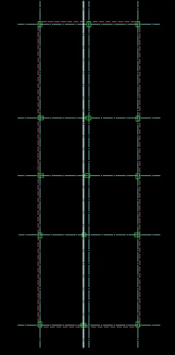
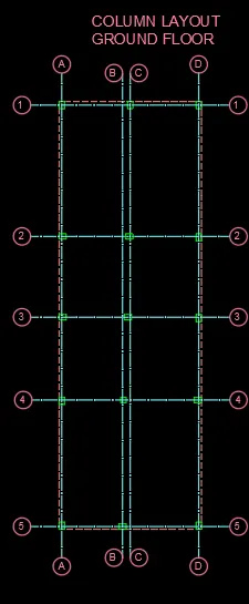
Write labels and numbering in both directions to all lines drawn
RESULT:-
We have genarated the Column Layout Drawing and labelled with details.
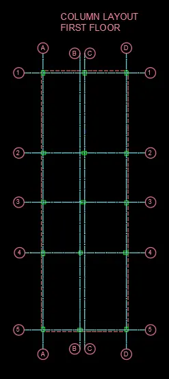
If required repeat the same process for First Floor
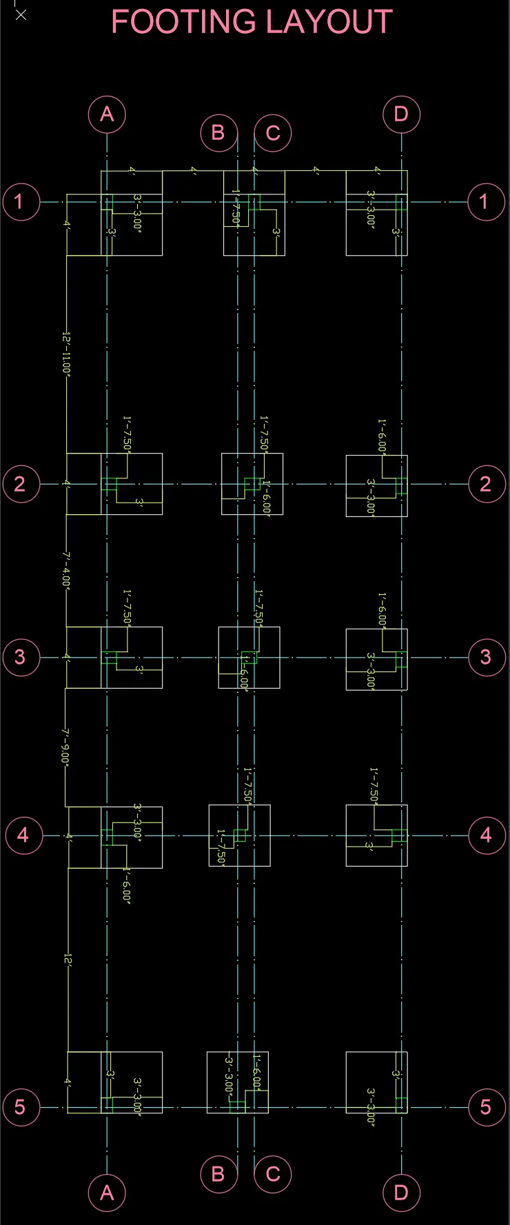
- FOOTING LAYOUT
AIM: -
Create the FOOTING LAYOUT
Use proper dimension techniques and dimension styles
Use Layers.
PROCEDURE: -
In the Column Layout drawing we have drawn mark the footing to each column.
Assume the Footing size is same to all columns.
Size of Footing : 4' x 4' units.
Position the Footings such that all the Footings are within the plot size.
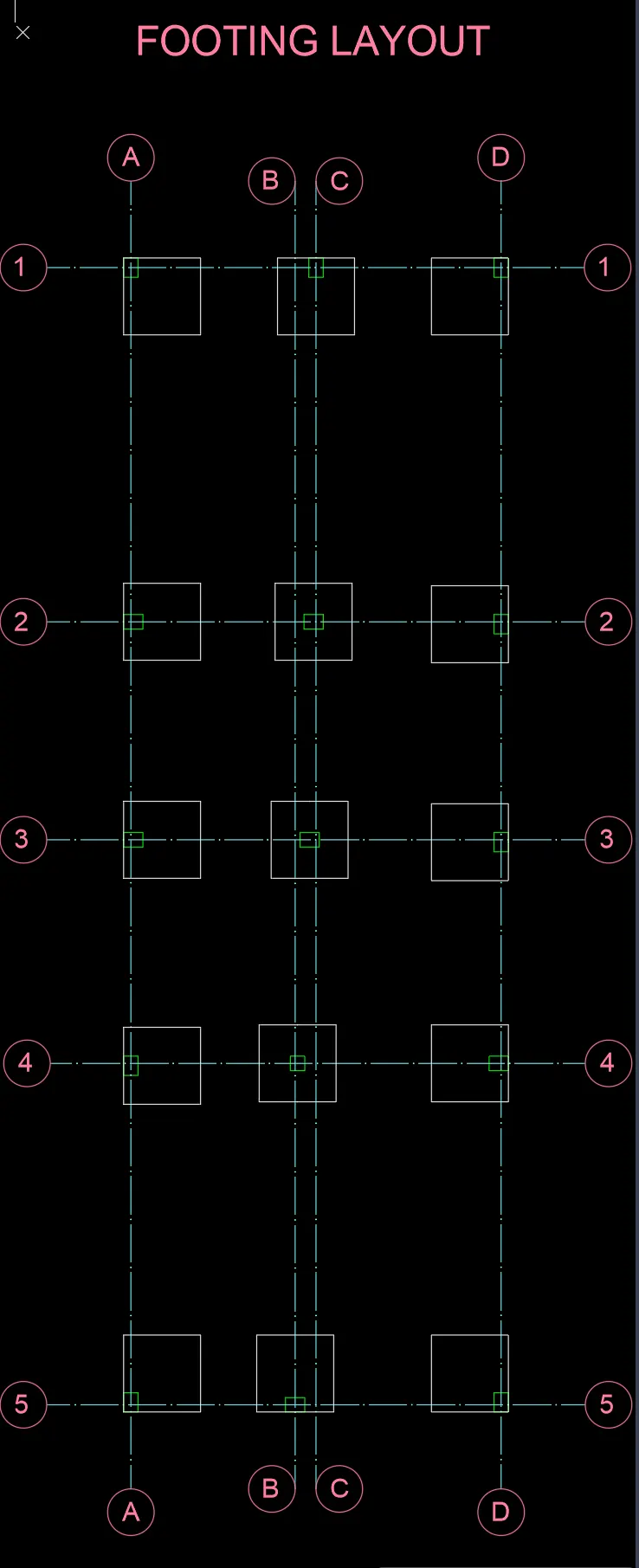
Label the footings.
Provide dimensions to these footings.
RESULT: -
Footing Layout with Text and Dimensions for each footing
- BEAM LAYOUT: -
AIM: -
Create the BEAM LAYOUT
Use proper dimension techniques and dimension styles
Use Layers.
PROCEDURE: -
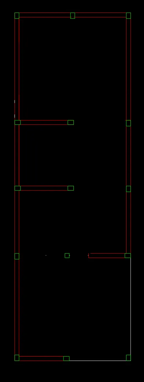
Hide all the layers in the Floor Plan
Turn on the Layers of Columns and outer walls.
All columns and outer walls are visible.
Select LAYER properties dialogue box
Create New Layers: BEAM LAYER
Line type: ISO DASH
Line weight: 0.30mm
Select different COLOUR to each layer created.
Draw Beams connecting column to column.
Assume beam size: 9" x 9" units.
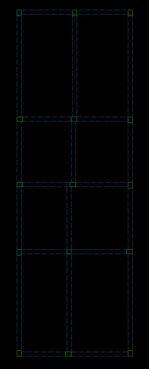
Label each beam.
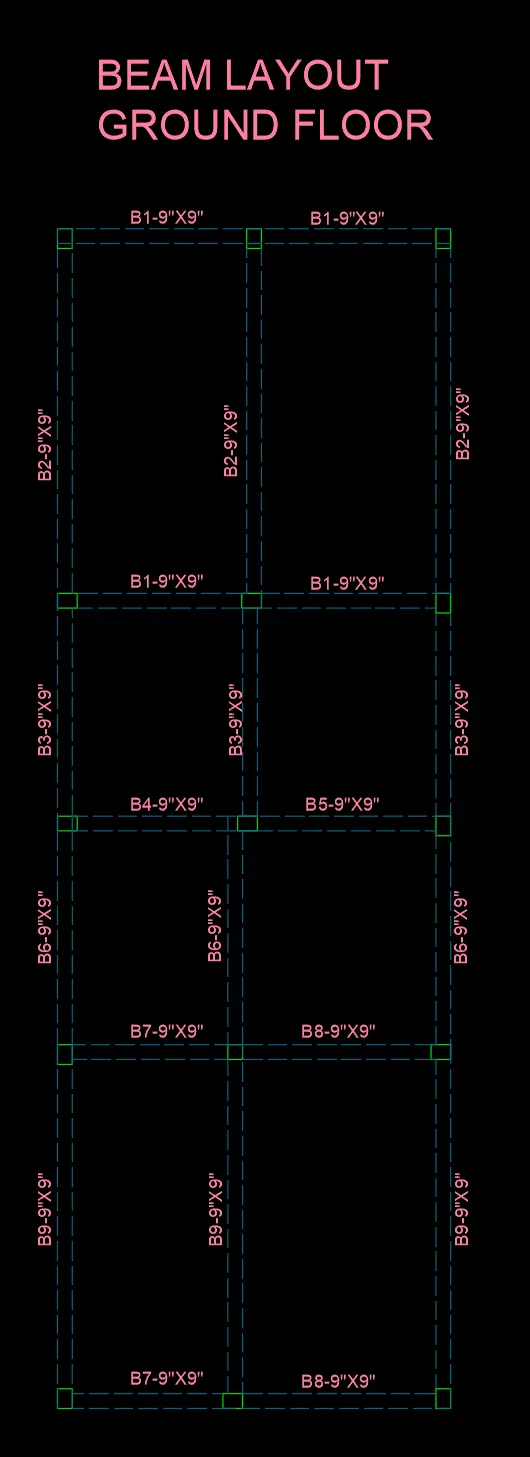
Provide dimensins to all beams dfrawn.
RESULT: -
We have drawn the Beam Layout and labelled each beam with dimensions for ground Floor and First Floor
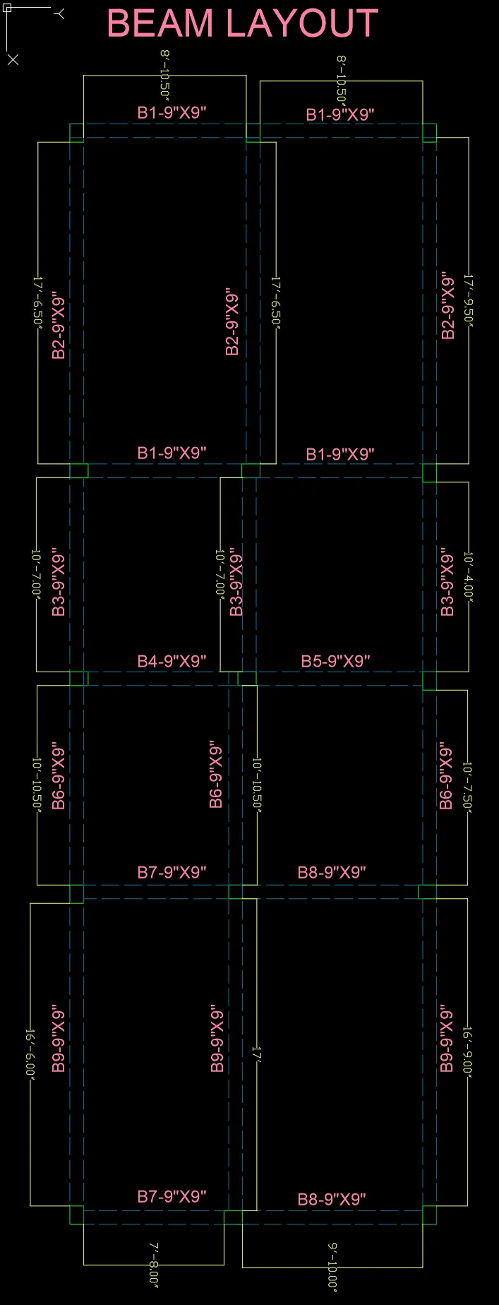
Beam Layout is same for the First floor