Project 1 _Creating an Architectural plan for the provided plot size and develop relevant basic structural drawings
Design and Draft a layout of a residential building with the following details:
a. Plot Size: 60’x20’ (18.3m x6m)
b. Orientation- Facing East
c. Develop the following:
1. Architectural Drawing (Floor Plan, Elevations, and Sections)
2. Structural Drawing (Column, Beam, Footing Plan)
Aim
The aim of the project is to design a Residential Space in a 60'x20' plot size having east orientation.
Procedure
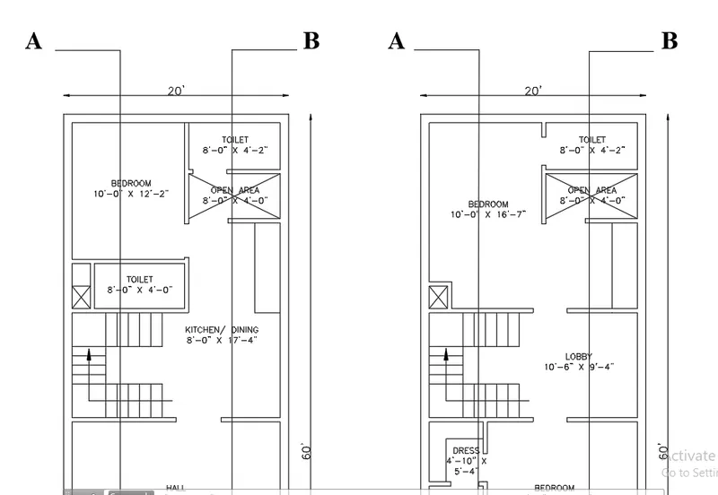
First, the size of the plot is marked with the help of construction lines after setting the limits and units of the drawing sheet to Architecture type
Construction lines in the horizontal and vertical directions are drawn using the command XL
A corner is created by trimming the bottom and left side of the construction line using the TRIM command
In order to create the outer wall, the OFFSET command is used with a distance of 9". Another offset of 4.5" is created for internal walls.
Create a bedroom of size 10” x 12’2”
Create toilets of sizes 8’ x 4’2’ and 8’ x 4’
Create an open space of size 8’ x 4’
Draw the dining cum kitchen area of size 8’ x 17’4”
Provide staircase in this area with riser 8.5” and tread 12”
Draw hall of size 18’6” x 14’
Draw another room of size 8’ x 10’6”
Draw porch area of size 10’2” x 17’6”
Create a lawn of size 8’5” x 6’8”
Provide doors of size 3’ using the TRIM command
Using the MTEXT command mention name and dimensions of each unit
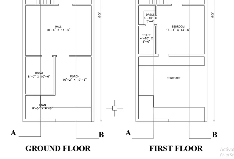
To create the first-floor plan copy the entire plan
Erase the toilet, making room size of 10’ x 16’7”
Create a lobby of size 10’6” x 9’4”
Provide a dress and toilet in the hall of sizes 4’10” x 5’4” and 4’10” x 8’
Combine room and porch to make an open terrace
Provide doors of size 3’ using the TRIM command
Using the MTEXT command mention name and dimensions of each unit
Result
Aim
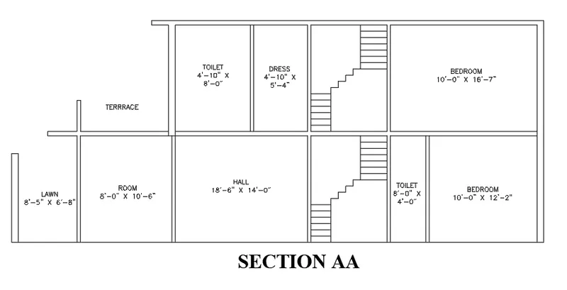
To create front elevation and sections of the residential plan
Procedure
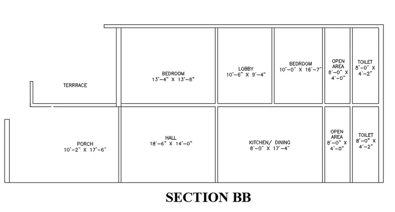
Construction lines are drawn as projections for the appropriate dimension of the room size and location of doors and windows
The floors are created with the OFFSET command with the appropriate floor height mentioned in the section
The inner wall offsets are 4.5” and the outer wall thickness is 9”.
The staircase with the tread of 12” and the riser with 8.5” is drawn
Put the dimensions where ever they are required in the section drawing as shown below.
Select the single text command to indicate the parts in the section plan.
Finally, draw the section line in the section plan as shown in the below figure.
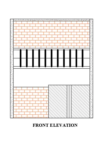
To create the front elevation draw the projections of the outer wall
Provide the front door at its location
The floors are created with the OFFSET command with the appropriate floor height mentioned in the section
Using the HATCH command fill the walls, front door, and column with proper hatch
Result
Aim
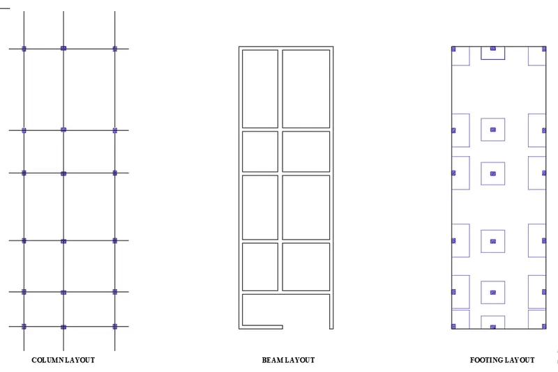
To create structural drawings including column, beam and footing layout
Procedure
Provide columns at proper locations having sizes of 9” x 12” and 12” x 9”
Copy all the columns to a different location
Draw a centre line plan intersecting all columns in straight lines
To create the beam layout join all the columns with appropriate beam sizes
Using the OFFSET command offset the column with 2’ for interior column footing and 3’ for exterior column footings.
Remove the unnecessary lines using the TRIM and ERASE command
Result