Project 1 _Creating an Architectural plan for the provided plot size and develop relevant basic structural drawings
- AIM: To design and design and layout of a residential building having plot size 60'X 20' facing east direction
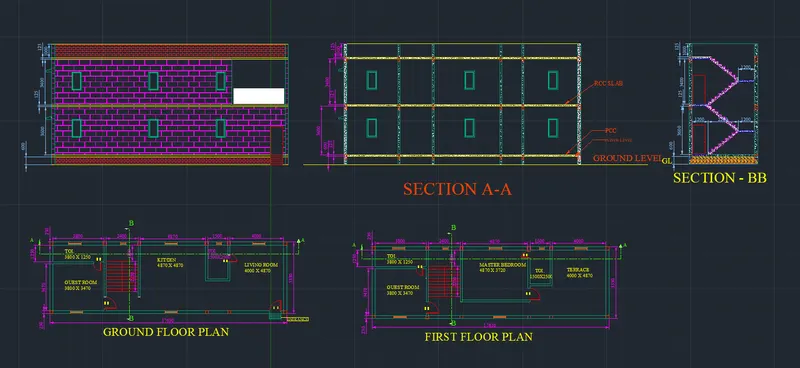
- ARCHITECTURAL DRAWING
- Site plan layout
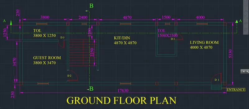
- Ground floor plan
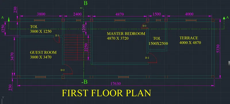
- First floor plan
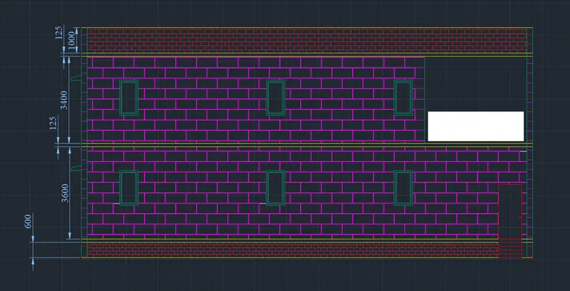
- Elevation
- Section view
- STRUCTURAL DRAWING
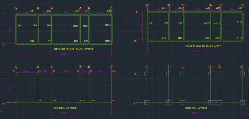
- Column layout
- Beam layout
- Footing layot
- PROCEdDURE
- Drop the layer menu select the wall layer and select the wall layer
- Create the rectangleof dimension of 17730 X 5330 and press enter
- Specify the offset distance of 230mm and 150 mm for the internal wall
- Specifythe offfset the distance of 3800mm
- Specify the offset the distance of 150 mm
- Specify the offset distance of 2400mm
- Specify the offset distance of 150mm
- Specify the offset distance of 4870mm
- Specify the offset distance of 150mm
- Specify the offset distance of 1500mm and trim the extra portion
- Specify the offset distance of 150mm and press enter
- Specify the offset the distance of 1250mm and press enter
- Specify the offset distance of 150mm
- Specify the offset distance of as 2500mm and press enter
- Select the ''tr'' remove the unwanted error
- Used the trim command to make the opening for the door
- Drop down layer and select the door layer
- Using ctrl+2 set the windows
- Creating the Text
- Drop the layer down and select the ''text'' layer
- Go to annotation tab and multitext command
- Select the text style as ''Times new roman''
- Specify the height and scale
- Select the text and change the text as per requirement
- Create the Dimension
- Drop the layer menu and select ''DIMENSION'' layer
- Give all the linear dimension
- CREATING THE FRONT ELEVATION
- Type ''xl'' in the command box press enter
- Select the points required to take the projection for elevation
- Specify the offset the distance as 600 and preess enter
- Specify the offser t distance 125 and press enter
- Specify offset distance as 3600
- Specify offset distance as 125
- Specify offset distance as 3400
- Specify offset distance as 125
- Specify offset distance as 1000
- Type ''TR'' in the command box trim all the section
- Select the horizontal layer and put them into ''SLAB'' layer
- Change the current layer to ''WINDOWS'' layer
- Specify offset distance as 1200 anad press enter
- Draw window with 1000 X 1500
- Create the HATCH in front elevation drawing
- Type ''hatch'' for command press enter
- Select the hatch from the hatch pattern and create the hatch to diffrentiate the wall ,slab, windows
- After the defining the hatch press ''enter''
- Create the DIMENSION in front elevation drawing
- Drop the layer menu and select the dimension layer
- Give all linear dimension
- RESULT
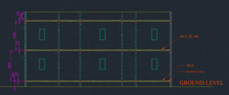
- CREATING THE SECTION AA LAYER
- Type ''xl'' in command box and press enter
- Select the points to take the section A-A
- Draw a horizontal line for ground level which cuts all vertical projection
- Take this horizontal line as ground level
- Specify offset distance as 600
- Specify offset distance as 125
- Specify offset distance as 3600
- Specify offset distanc as 125
- Specify offset distnce as 3400
- Specify offset distance as 125
- Specify offset distance as 1000
- Select all offset line and designate them as slab layer
- Provide window from ''ADS''
- Give dimension from ''DIMENSION'' layer
- RESULT
- Creating the section B-B
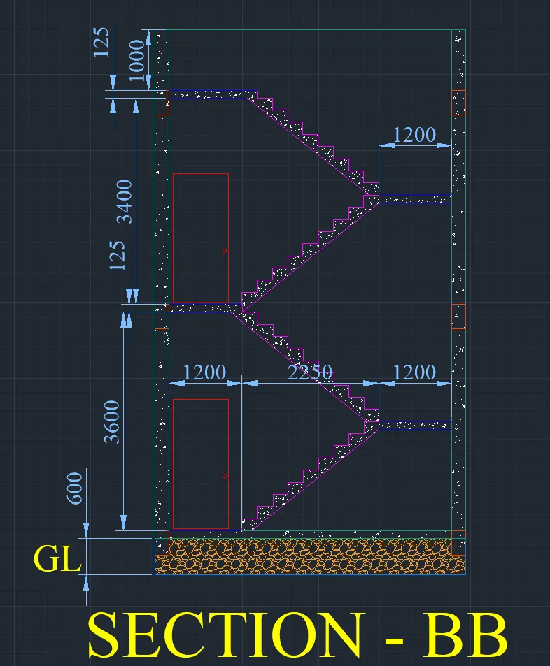
- Type ''XL'' in the command to draw a horizontal line and vertical line
- Use the projection to find the edges of doors,slabs,windows,
- Draw the staircase with riser 200mm and tread 250mm
- Mark the projection of doors and select the door layers from layer tab and make the door size of 1000mm X 2000mm
- Trim the remaining section
- Place the beam as per plan
- Hatch the wall area ; staircase area to show the rcc work
- Give the dimension through ''DIMENSI0N'' layer
- RESULT
- ARCHITECTURAL DRAWING
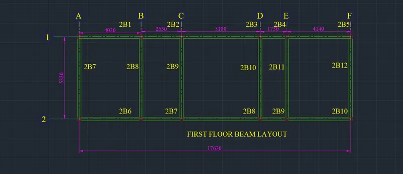
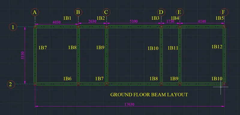
- CRREATING THE BEAM LAYOUT FOR FIRST FLOOR AND GROUND FLOOR
- Draw the centre line through middle of centre line
- Extend the centre line from each column froom their centre point
- Draw the circle and copy that circle to extension line of that centre line
- Turn off the layer and give the dimension to the drawing
- Give names to each beams
- RESULT
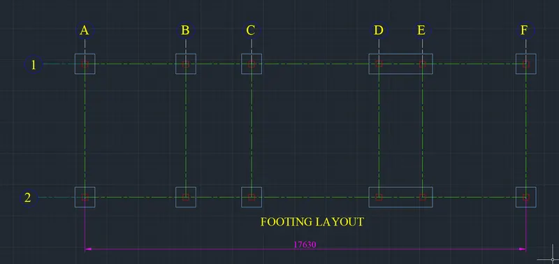
- CREATING AN FOOTING LAYOUT
- Draw the centre line through middle of centre line
- Extend the centre line from each column froom their centre point
- Size of isolted footing is taken as 800X 800 and footing is laid out except D1,D2 ,E1,E2
- For remaining footing size is taken as 2350 X 900
- Give all title to the drawing and the diimension to the drawing
- RESULT
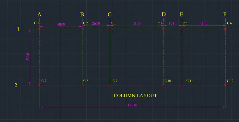
- CREATING AN COLUMN LAYOUT
- Draw the centre line through middle of centre line
- Extend the centre line from each column froom their centre point
- Names are given to the resp. column and dimensions are designated
- RESULT
- STRUCTURAL DRAWING