Project 1 _Creating an Architectural plan for the provided plot size and develop relevant basic structural drawings
ANSWERS:
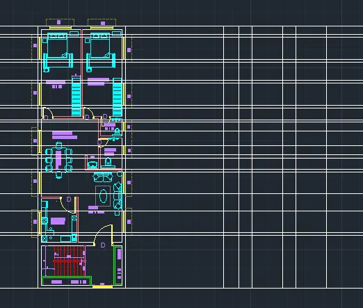
AIM: To create the 60'X20' EAST Facing Plan Layout, Column Layout, Footing Layout, Section and Elevation, with the help of Line, Rectangle, offset, Trim, extend, Xline command as shown in the figure above in AutoCAD.
INTRODUCTION: The desired Archetectural and Structural PLAN, SECTION & ELEVATION , COLUMN, & FOOTING Layout, Dimension is created in AutoCAD using primarily the Line tool, XLINE, Offset The procedure of drawing is explained in detail with diagrams of each step and the final result is given.
PROCEDURE:
Go to START MENU, select AutoCAD 2022.
In the Command line type in: STARTUP ,
Enter new value of start-up: 1
Go to Application Menu and select New
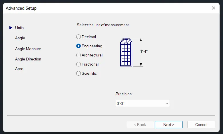
In the 'Create New Drawing' dialog box, we do the Advanced Setup and select the ENGINEERING unit of measurement and select precision as 0’0”
Set the limits by entering LIMITS in the Command tab. The lower-left corner is specified as 0,0 and the upper-right corner is specified as 10000,10000
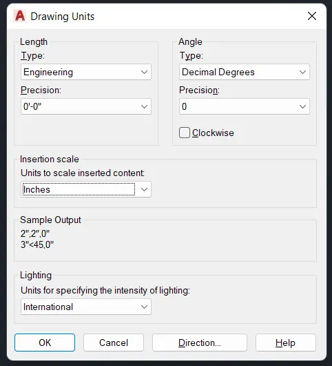
Enter 'UNITS' command in the command tab.
In the Drawing Units dialog box, select ENGINEERING in Type 0’-0” in Precision and INCHES in Insertion scale.
Click on 'OK'.
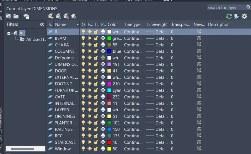
LAYER: Create the Required Layers Assign Specific Colour to the Layer as Shown in Figure
To Cancel Selected Command Press “ESC”
To Invoke Previously Selected Command Press “ENTER”
ARCHETECTURAL DRAWING:
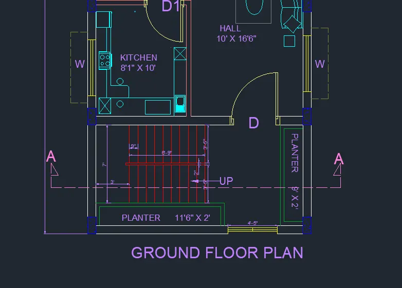
PLAN
WALL:
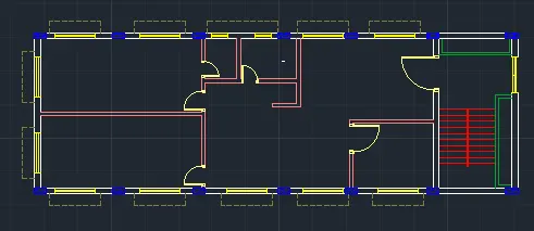
LAYER: EXTERNAL WALL
XLINE: Create Horizontal and Vertical lines
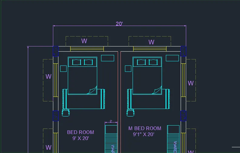
RECTANGLE: Specify the 20'x60'
OFFSET: Specify the OFFSET of 9" and Drag inside the Rectangle
(DUE TO CLEAR VISIBILITY PLOT IS ROTATED LEFT)
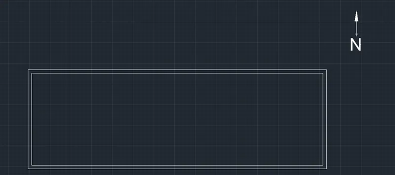
OFFSET: Create Vertical OFFSETS at a Distance of 9”,9’, 5”, 9’1” in +X Direction
Create Horizontal Offsets at a Distance of 9”,9’,9”,10’,5”,17’11”,5”,20’ in +Y Direction
TRIM : Cut off all Unwanted Lines and keep the wall lines as per the plan and Save the Drawing
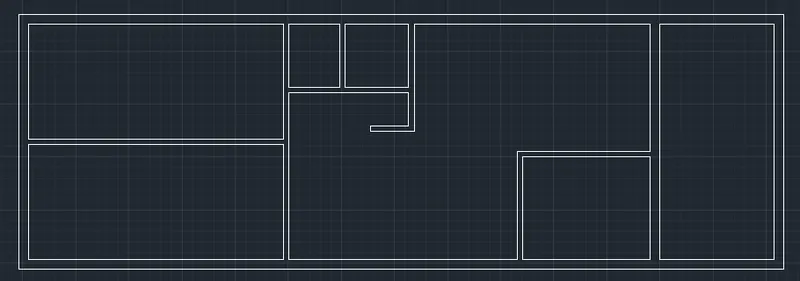
LAYER: INETRNAL WALL
Select all the Walls having Thickness 5” assign it to the” for Internal wall Layer
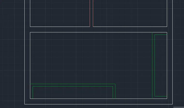
PLANTER BOX:
LAYER : Planter Box
RECTANGLE: Create the Planter Box 11'6"x2' and 2'x9'
OFFSET: Create the offset of 4" and drag inside
DOORS AND WINDOWS
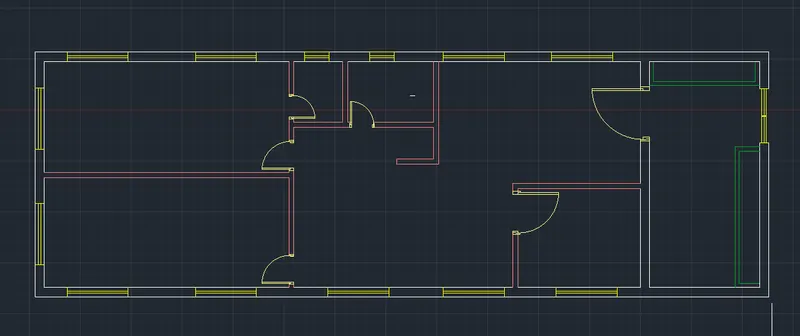
LAYER: DOOR
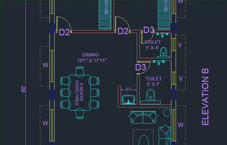
INSERT: insert the Door and Scale it to the Desired D, D1, D2, D3 specified as below
SIZES: DOORS D-4’, D1- 3’6”, D2-3”, D3- 2’6” Specify and Assign to the Desired Rooms as shown Below
LAYER: WINDOW
To create the Windows select Midpoint of the wall of a Room specify half of the window size and Draw the Line 9”, select the 9”line and offset at a distance of 5’, specify the line of 5’ and 3” twice to make window frame
WINDOWS W-5’, V-2’
PROJECTION
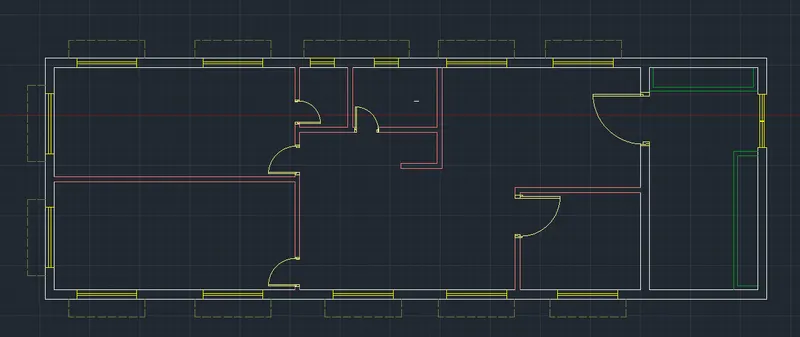
LAYER: PROJECTION
LINE: line type as DASHED, Scale: 15
Create the projection from each window with Projection width of 1’6” and bearing of 8” from both end of windows
STAIRCASE
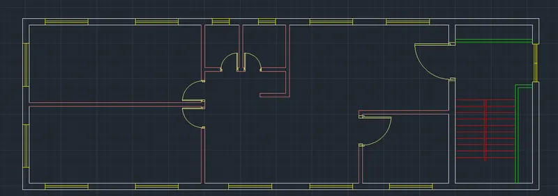
LAYER: STAIRCASE
OFFSET: Create The offset of 3’ from wall end and then Create 9 Offset of 9” to create Treads of stairs
RECTANGLE: Create a Rectangle of 7’1” x 2” place it at Centre originating from the start point of stair at a distance of 3’5” from external wall as shown in figure
LEADER: Create a leader and type UP Show the direction as shown in figure
To Create the Columns
LAYER: COLUMN
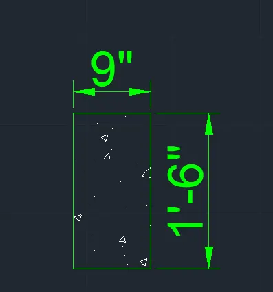
RECTANGLE: Create the Rectangle of 9”X1’6”
HATCH: Pattern AR-CONC, Scale:1
Create the Hatch inside the Rectangle to make Columns
COPY: copy and Paste the Columns in desired positions
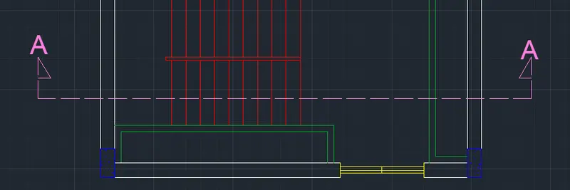
LAYER: Section line
LINE: Line type CENTRE 2, Scale 100
Create the line to show the Section line Type SECTION AA
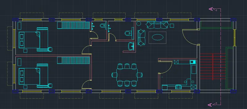
LAYER: DIMENSIONS
INSERT: Go to insert menu and select the Required Furniture and Bathroom fittings and Place it in desired Locations
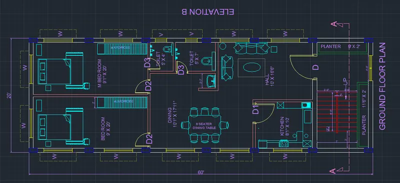
LAYER: Dimensions
DIMLENIAR: Select and Place the Desired Dimensions, Represent all the Dimensions
DIMSTY: Set Arrow size 100, Text Height 7”, Precision to 0
DIMCONTINUE: Create Remaining Dimensions
MTEXT: Create a Text Box and Enter the sample text, Copy and Paste multiple in Desired Position and desired angle with Desired Size
EDIT TEXT (ED): Edit the MTEXT Created and Pasted and Type the actual name, size, rotation angle
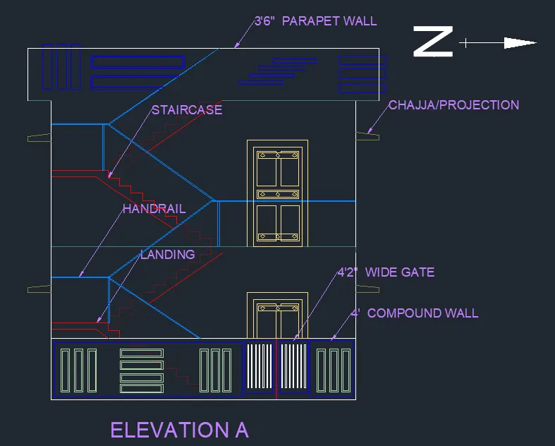
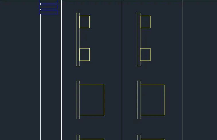
ELEVATION A
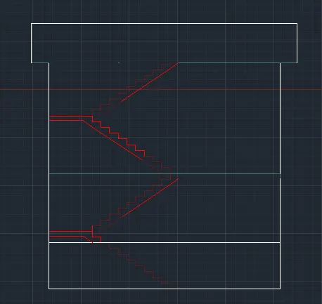
XLINE: Project the all the line Visible in the Front View
FLOORS
OFFSET: Crete the base line as GL continue offset of 10’ in +Y to Create floors
Specify and offset of 5” from Each Floor in -Y directions as Slab Thickness
STAIRS:
Create the Stairs of risers as 6”, Treads as 9”, Create the Landing at a Height of 5’from ground level Continue the same till the Terrace floor
DOOR:
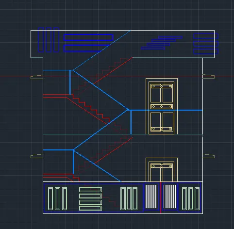
LAYER: DOOR
XLINE: Create the XLINE from the Door to
RECTANGLE: Create the Rectangle inside Vertically Projected Lines Create the offset from 7’ as the Height of the door
Delete the XLINES
CHAJJA: Create the Line of 1’6” in +X, 4”in +Y, 1’6”in -X at a Distance of 6”from base
COPY: Copy and paste it in Desired Positions and Levels
OFFSET: Specify an offset of 100 and drag towards inward
RECTANGLE: Specify 500x 70 and 800x 30 position it one over the other and keep it at the top of OHT
LAYER: Section line
LINE: Line type CENTRE 2, Scale 100
Create the line to show the Section line Type SECTION BB
LAYER: Dimensions
DIMLENIAR: Select and Place the Desired Dimensions, Represent all the Dimensions
DIMSTY: Set Arrow size 12”, Text Height 7”, Precision to 0
DIMCONTINUE: Create Remaining Dimensions
MTEXT: Create a Text Box and Enter the sample text, Copy and Paste multiple in Desired Position and desired angle with Desired Size
EDIT TEXT (ED): Edit the MTEXT Created and Pasted and Type the actual name, size, rotation angle
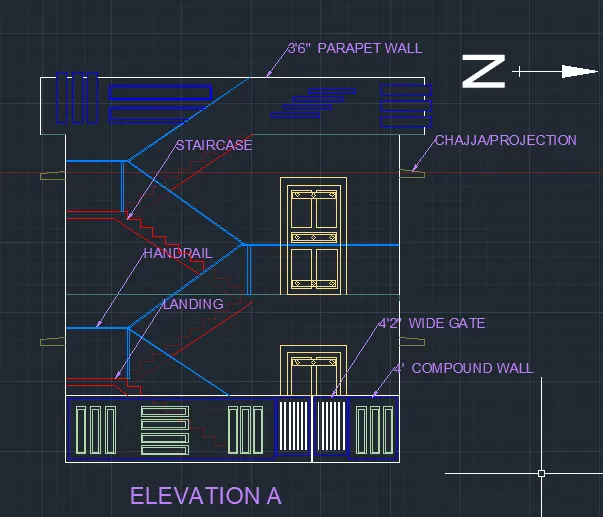
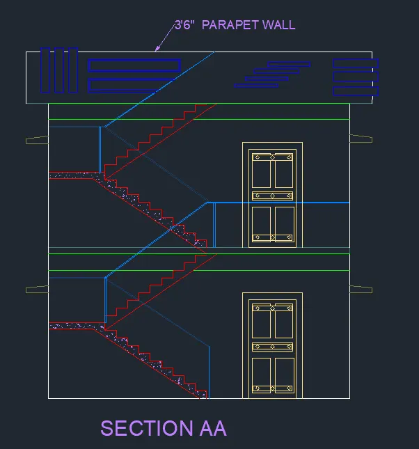
SECTON A
COPY: copy and Paste Elevation A
FLOORS
OFFSET: Crete the base line as GL continue offset of 10’ in +Y to Create floors
Specify and offset of 5” from Each Floor in -Y directions as Slab Thickness
BEAMS
LAYER: BEAM
RECTANGLE: Size of the Beam is 9”x18”
OFFSET: Draw the Beam of 18” by offsetting the Slab
STAIRS:
Create the Stairs of risers as 6”, Treads as 9”, Create the Landing at a Height of 5’from ground level Continue the same till the Terrace floor
DOOR:
LAYER: DOOR
XLINE: Create the XLINE from the Door to
RECTANGLE: Create the Rectangle inside Vertically Projected Lines Create the offset from 7’ as the Height of the door
Delete the XLINES
CHAJJA: Create the Line of 1’6” in +X, 4”in +Y, 1’6”in -X at a Distance of 6”from base
COPY: Copy and paste it in Desired Positions and Levels
OFFSET: Specify an offset of 100 and drag towards inward
RECTANGLE: Specify 500x 70 and 800x 30 position it one over the other and keep it at the top of OHT
LAYER: Section line
LINE: Line type CENTRE 2, Scale 100
Create the line to show the Section line Type SECTION BB
LAYER: Dimensions
DIMLENIAR: Select and Place the Desired Dimensions, Represent all the Dimensions
DIMSTY: Set Arrow size 12”, Text Height 7”, Precision to 0
DIMCONTINUE: Create Remaining Dimensions
MTEXT: Create a Text Box and Enter the sample text, Copy and Paste multiple in Desired Position and desired angle with Desired Size
EDIT TEXT (ED): Edit the MTEXT Created and Pasted and Type the actual name, size, rotation angle
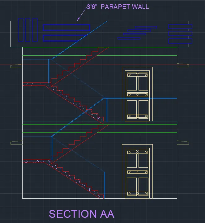
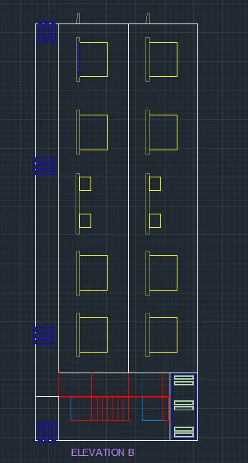
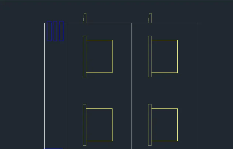
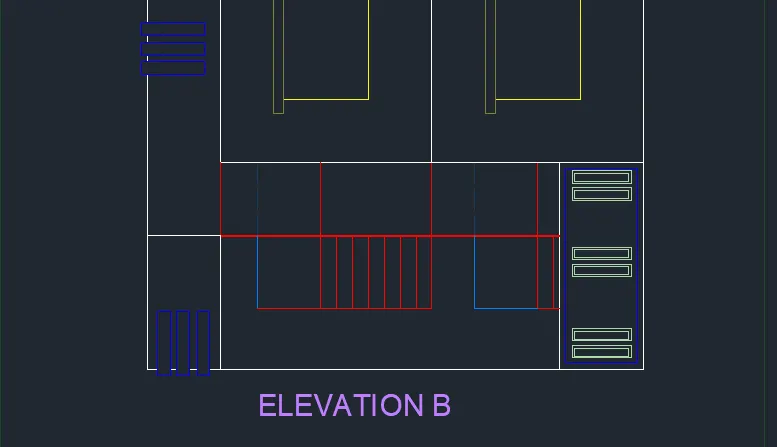
ELEVATION B
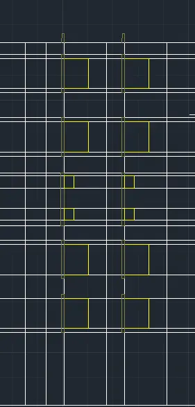
XLINE: Project all the line which is visible from Elevation B and Section AA
LINE: Create the WINDOW, PROJECTION, FLOOR, PARAPET PALL in Respective Layer
STRUCTURAL DRAWING:
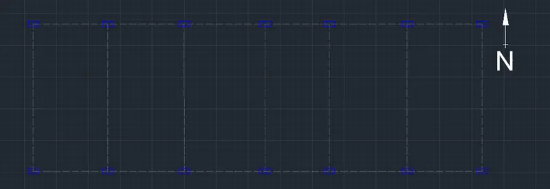
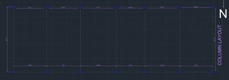
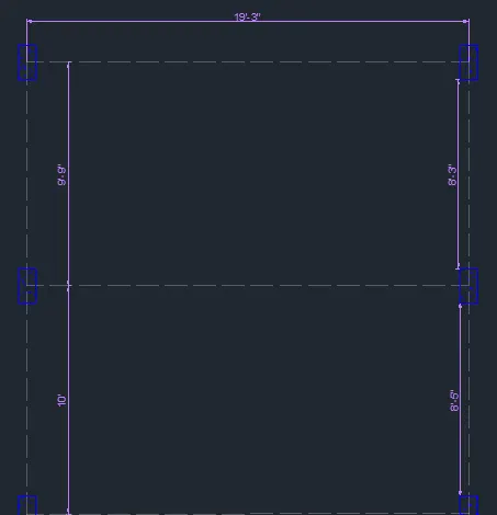
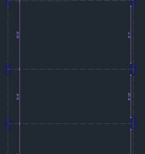
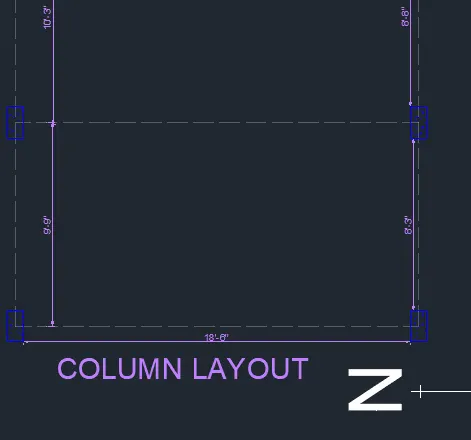
COLUMN LAYOUT
RECTANGLE: Specify 9”x18” as the Column size
COPY: Select all the Columns and Copy and Paste it
LINE: Select the line type as ISO DASH and Transparency as 75 and Draw the Line at the Centre of the Columns Connect all the Columns
LAYER: Dimensions
DIMLENIAR: Select and Place the Desired Dimensions, Represent all the Dimensions
DIMSTY: Set Arrow size 12”, Text Height 7”, Precision to 0
DIMCONTINUE: Create Remaining Dimensions
MTEXT: Create a Text Box and Enter the sample text, Copy and Paste multiple in Desired Position and desired angle with Desired Size
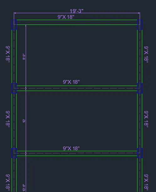
BEAM LAYOUT:
LAYER: BEAM
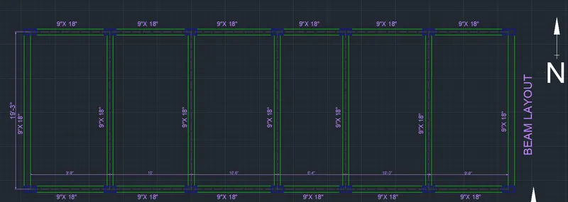
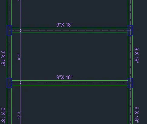
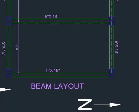
COPY: Copy the Column layout and draw the Beam beam between the Columns as shown in figure
BEAM SIZE: 9" X 18"
LINE: Draw the Line between the Columns to Create the Beam
LAYER: Dimensions
DIMLENIAR: Select and Place the Desired Dimensions, Represent all the Dimensions
DIMSTY: Set Arrow size 12”, Text Height 7”, Precision to 0
DIMCONTINUE: Create Remaining Dimensions
MTEXT: Create a Text Box and Enter the sample text, Copy and Paste multiple in Desired Position and desired angle with Desired Size
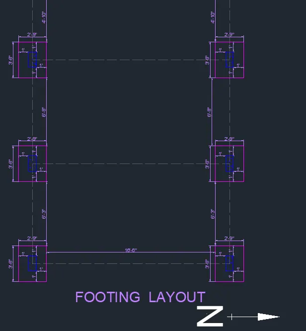
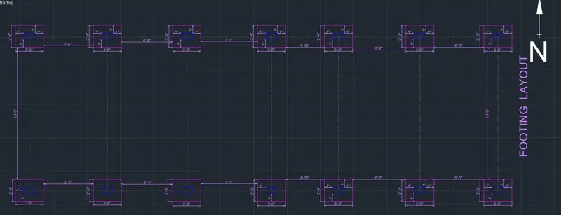
FOOTING LAYOUT:
LAYER: Footing
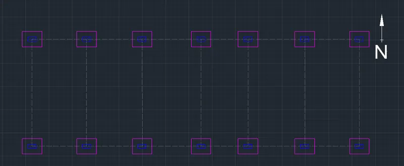
COPY: Copy the COLUMN LAYOUT and paste it
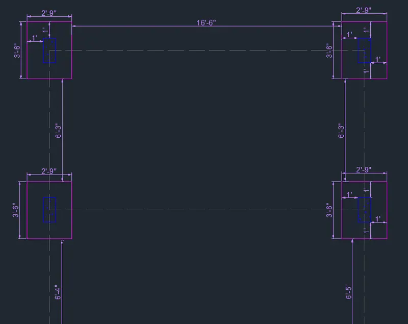
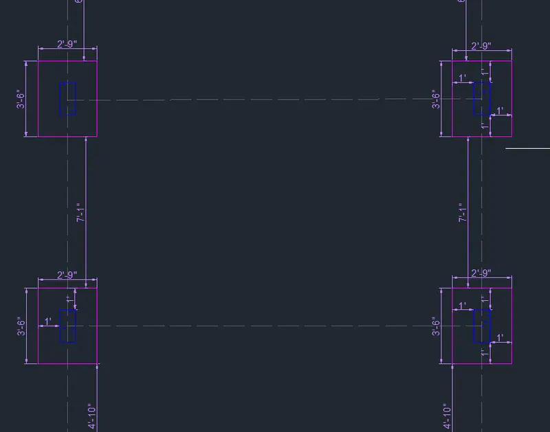
RECTANGLE: Specify the Rectangle as 2’9”and 3’6” as Footing
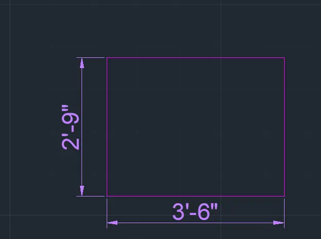
COPY: Copy the Footing Paste it on all the Columns by keeping the Column centre as the Centre point
LAYER: Dimensions
DIMLENIAR: Select and Place the Desired Dimensions, Represent all the Dimensions
DIMSTY: Set Arrow size 12”, Text Height 7”, Precision to 0
DIMCONTINUE: Create Remaining Dimensions
MTEXT: Create a Text Box and Enter the sample text, Copy and Paste multiple in Desired Position and desired angle with Desired Size
RESULT:
PLAN
ELEVATION A
SECTION AA
ELEVATION B
COLUMN LAYOUT:
BEAM LAYOUT:
FOOTING LAYOUT: