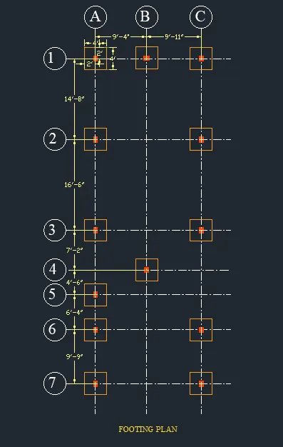
Project 1 _Creating an Architectural plan for the provided plot size and develop relevant basic structural drawings
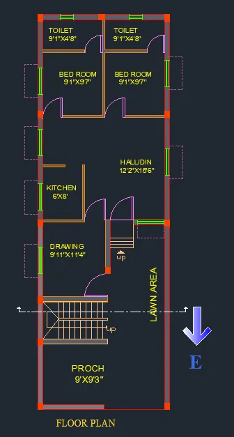
Aim: Design and Draft a layout of a residential building with the following details:
a.Plot Size: 60’x20’(18.3m x6m)
b. Orientation- Facing East
Introduction: Design and Draft a layout of a residential building with the following details. By using AutoCad.
a.Plot Size: 60’x20’(18.3m x6m)
b. Orientation- Facing East
Procedure:
Architectural Drawing:
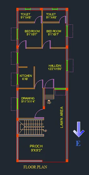
Floor Plan:
Step1:
- Frist set the units by typing “UN” in the command
- Set the units in the imperial format
- Next set the limits as per the required of plan. Let set the lower corner as (0’,0’)and upper corner as (100’,100’).
Step2:
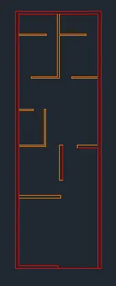
CREATION OF EXTERNAL AND INTERNAL WALLS OF THE GIVEN PLAN:
- Now take the command “XL” for the construction line V for the vertical line and H for the horizontal line
- Now next take the offset command and make the 9” offset for all the external walls and 4.5” for all the internal walls
Step3:
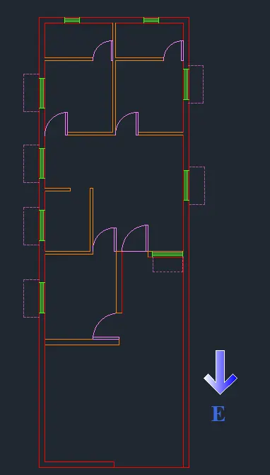
CREATING AND PLACING OF WINDOWS AND DOORS:
- W1=3’, w2= 2’
- D1=3’6”, D2=3, D3=2’6”
- First create a window and door make it as a block by using the command B select the pick point then select the object give the names of the block
- Next select the rotated, copy, and move as per required of placing the object
Step4:
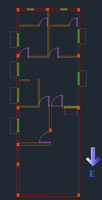
CREATING AND PLACING OF COLUMNS:
- Assume all the columns are 9”x12”” (230x460mm)
- Frist take the rectangle “REC” @9”X12”
- Rotated the columns as per need of structure
- Take the hatch command and mark the hatch in the columns
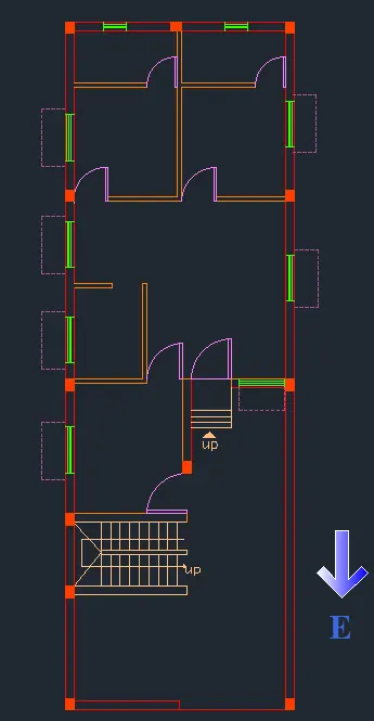
Step5:
CREATING OF STARE CASE:
- Take the line command and mark the line from start point end of the wall and take the offset of 10”mm for trade and 6”mm for the riser
Step6:
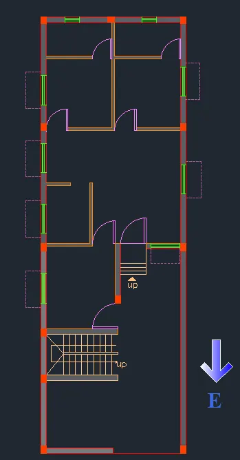
CREATING OF HATCH:
- For hatch take the command hatch select the type of hatch as soled
- Take the cursor at the close boundary of and click for the hatching
- Increase the hatch transparence and angle as per required
Step7:
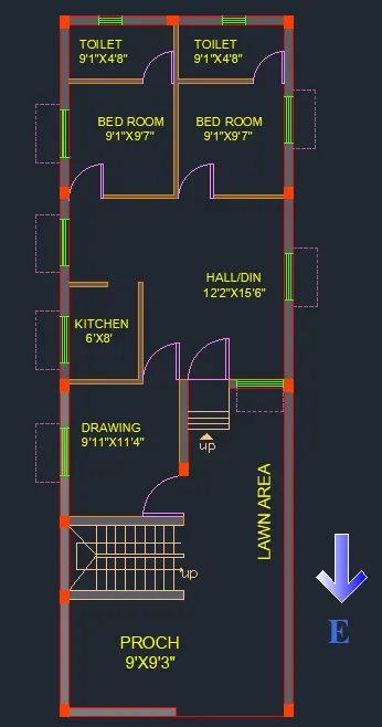
CREATION OF TEXT AND DIMENSIONS:
- take the command mtext select the base point write the text set the height of the text
- next copy the and place the text and then edit as per the required of the text
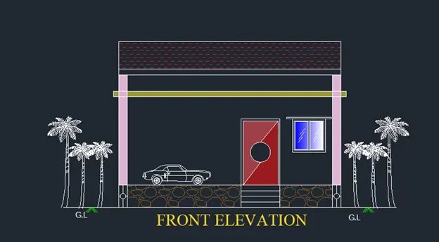
Elevations:
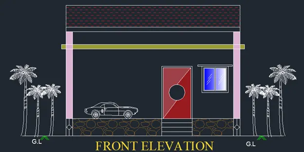
step1:
- first take a XL line and v for the vertical and H for horizontal reference from the above plan mark the edge lines of the columns
- Now continue to XL line mark the ground level line then take the offset of and 2’ for the plinth level.
- Next take the offset of 10’ from the base point for the height of first slab and take the 6” f offset for the thickness of the slab next the offset 3’ for the height of the parapet wall.
- Now take the construction line by using the command XL and v for the vertical line and the references lines for the doors and windows from the floor plan
- Take the rectangle command make the rectangle from the reference line joining points for the creation of windows and doors
- Now take the hatch command for the hatching the windows, door, plinth level, columns and other things.
- Next press the ctrl+3 for toll palettes now go architectural imperial for tress, and car.
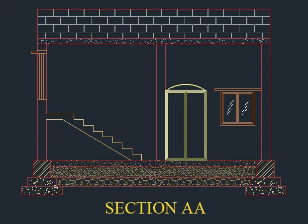
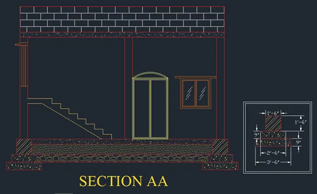
Section AA:
Step:1
- Frist cut the section line from the floor plan as shown
- first take a XL line and v for the vertical and H for horizontal reference from the above plan mark the edge lines of the columns
- Now take the construction line by using the command XL and v for the vertical line and the references lines for the doors and windows and staircase from the floor plan
- Take the reference line for the staircase mark the trade as 10” and riser as 6”.
- For the footing take a rec of 3’.6”x9”, 2’6”x9” 1’6”x1’6” place the rec one upon other from the midpoint
- Next take the offset of 10’ from the base point for the height of first slab and take the 6” f offset for the thickness of the slab next the offset 3’ for the height of the parapet wall.
- Now take the hatch command for the hatching the windows, door, plinth level, columns and other things.
Structural Drawing:
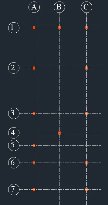
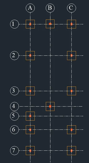
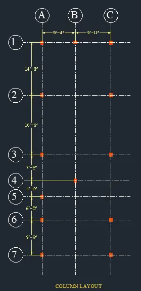
Column layout:
Step1:
- First copy all the columns from the floor plan.
Step:2
- now change line type take the line as center line.
- Now take the construction line by using the command XL and v for the vertical line and H for the horizontal line
- Noe from the center of each line mark the line
- Now take the circle of 2’ and type the text for the numbering of the columns
- Now copy the text move and place as per the requirement
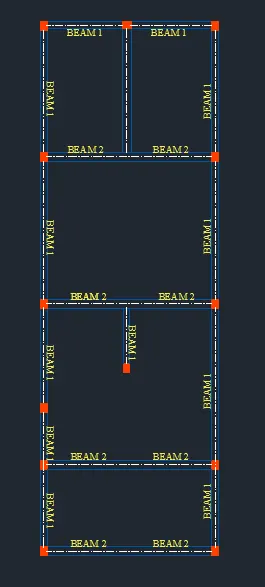
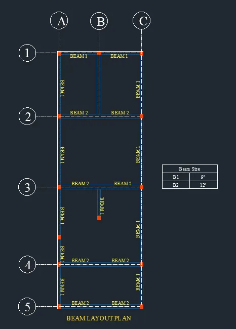
Beam layout plan:
step1:
- First copy all the columns from the column layout
- Now take the line command and mark the line between the column to column for the identification of beam
- The line joining from column to column is main beam and line joining from the column to beam is secondary beam
- Next go to annotation tool take the central line and mark the central line between the lines of the beam
- Next take the text command give name and numbering for the beam
Footing plan:
Step1:
- Copy column layout plan for the creation of footing plan
- Next take the rec command for creating rectangle of size 4’x4’ for the footing
- Now take the copy and move command select the rectangle select the pick point and place at the center of the columns
- Now copy the text move and place as per the requirement
Result:
Architectural Drawing:
Floor Plan:
Elevations:
Section AA:
Structural Drawing:
Column layout:
Beam layout plan:
Footing plan: