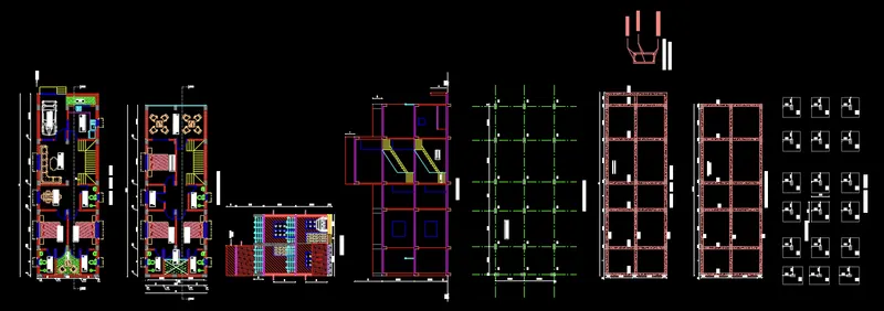
Project 1 _Creating an Architectural plan for the provided plot size and develop relevant basic structural drawings
AIM:
To create architectural drawing for a plot size 60’x20’ (floor plan, elevation, and section). The orientation of plot east facing and also develop relevant structure drawings (column, beam, footing plan)
Introduction:
The architectural drawing is created in AutoCAD by using the tools draw, modify, annotation, layers, block and properties. The procedure of architectural drawing is explained with figure and the final result is given.
Procedure:
STEP 1) Selection of Modal for Drawing
- Open AutoCAD
- STARTUP enter for new drawing
- Enter new value for startup 1 enter
- Create new file (a dialog box open)
- Go to last icon USE A WIZARD open
- Select ADVANCE SETUP click OK
- Select ENGINEERING, precision 0’-0.0” > NEXT > NEXT > NEXT > NEXT > FINISH
- UN enter for unit setting
- Select ENGINEERING, precision 0’-0.0” in type
- Insertion scale select INCHES Click OK
- LIM enter for set limit
- Specify lower left corner 0,0 enter
- Specify upper right corner 1000’,1000’ enter
- Z enter for zoom
- Zoom for select ALL or A enter
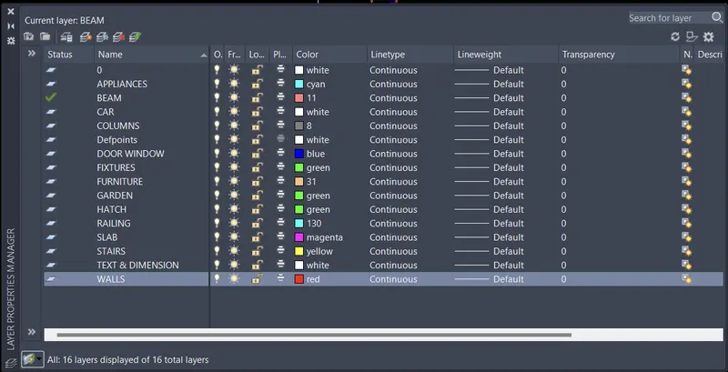
STEP 2) Layer Property
- Ribbon > Layer Properties
- Create New Layer > Rename Layer > Column, Wall, Stairs, furniture, Text & Dimension etc
- Change colour for different layer
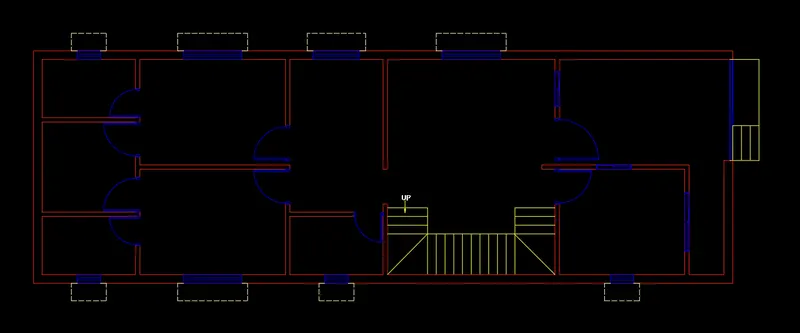
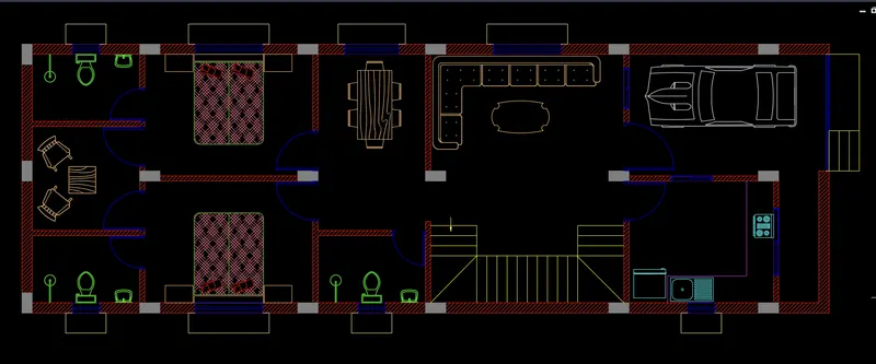
STEP 3) Architectural Ground Floor Plan
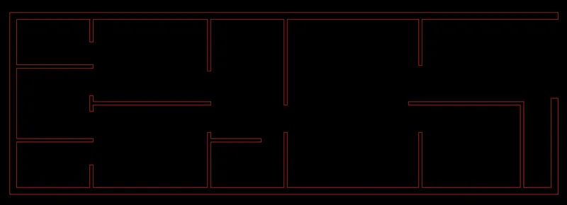
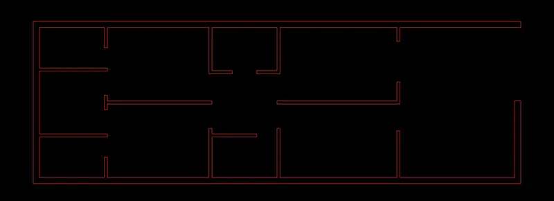
WALL
- Set layer as wall
- View cube on to create east facing plan
- Create rectangle of size 60’,20’ (plot size)
- Take inside offset of rectangle at 9” distance as external wall
- Explode both rectangle
- Take offset as per require room size
- Internal wall 4.5” thick
- Offset left to right
- First offset for toilet and OTS
- Then offset for bedrooms, dining room and common toilet, hall and staircase, kitchen and parking and last for lawn
- Take offset from top to part the rooms
- Trim, extend and erase command used to create opening for door
DOOR & WINDOW
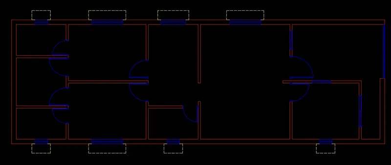
- Set layer as door and window
- For door window create with help of line and circle then convert into blocks
- Create different size of door, window and ventilation
STAIRCASE AND RAMP
- Set layer as stairs
- With help line and offset command to create stair and ramp where required
- QL enter for showing direction and text
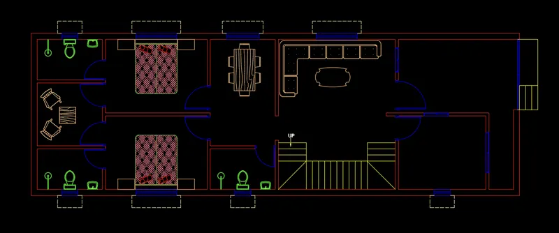
FURNITURE AND FIXTURE
- Set layer as furniture then insert furniture’s from design center
- Some furniture creates with the help of draw and modify tool
- Now set layer as fixture the insert items and some item made in last drawings
- Open recent blocks from insert ribbon, move in position then scale as per required dimension
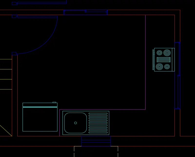
KITCHEN APPLIANCES
- Set layer as appliances
- Insert blocks from recent drawings
- Scale to set as required size
- Insert blocks like kitchen sink, hob, fridge
- With help of line command to create platform
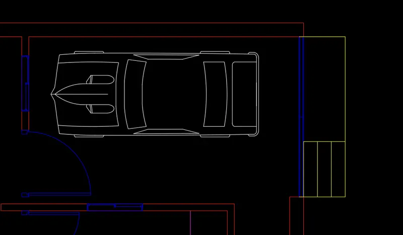
CAR
- Open tool pallets by entering tool pallets command
- In architectural tab select imperial car
- Drag to sheet
- Click on car then click on expand icon
- Select sport car plan
- Scale the car as per required size
COLUMN
- Set layer as column
- Create rectangle of size 9”x18”
- Solid Hatch fill in column
- Copy to place columns as per requirement
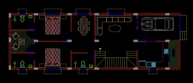
HATCH FOR WALL AND GARDEN AREA
- Set layer as hatch
- Use different pattern or scale for hatching
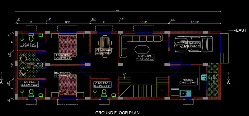
TEXT and DIMENSION
- Set layer as text and dimension
- Open style manager to set font and height of text
- Open dimension style manager
- Change arrow style
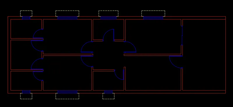
STEP 4) Architectural First Floor Plan
WALL
- Turn off all the layer except wall
- Select the wall then copy for first floor
- Some modifications for first floor like Bedroom, store room and balcony
- Created one room on above the hall and created a store room above the dining area
- Left out the balcony on above the kitchen
DOOR, WINDOW
- Copy door from the ground floor and place in first floor.
- Some extra door copies as per requirement
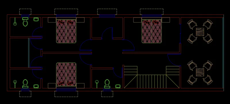
FURNITURE, FIXTURE, STAIRS, RAILINGS,
- Copy from ground floor
- Railing creates at end of balcony
- Hatch fill as per required
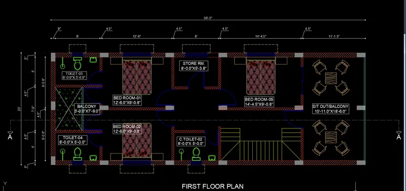
COLUMN, HATCH, TEXT & DIMENSION, SECTION LINE
- Copy column for above floor plan then place in position
- Same hatch created in first floor wall
- Provide required text and dimension
- Cut a section line for section AA
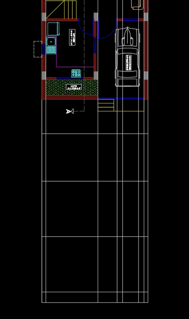
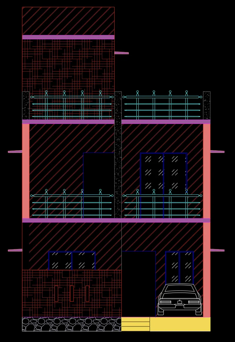
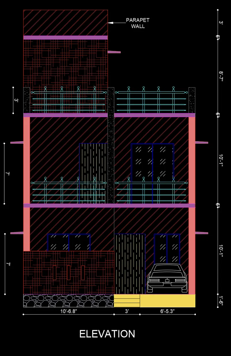
STEP 5) ELEVATION
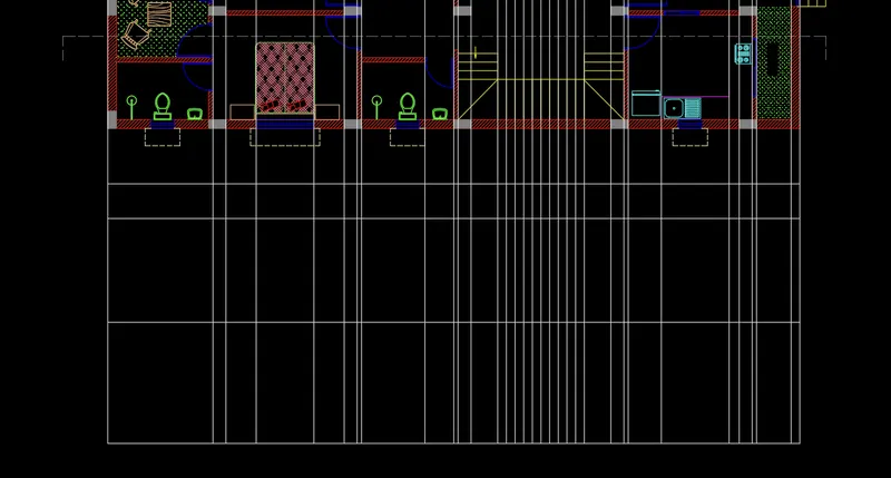
- Create construction lines for elevation
- Rotate drawing for better view
- Create offset for different floor level
- Trim and erase command used to remove unwanted lines
- Select layer as well as create particular member
- Hatch fill for showing different element
- Provide text and dimension as per required
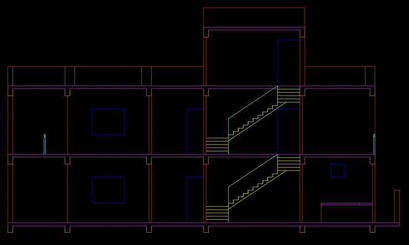
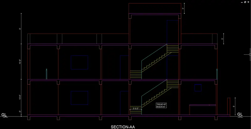
STEP 6) SECTION-A A
- For section to create construction line take reference from ground and first floor
- Create different floor level by offset command
- Provide text and dimension
STEP 7) COLUMN LAYOUT
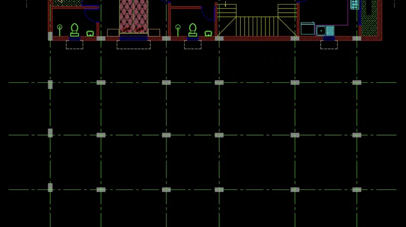
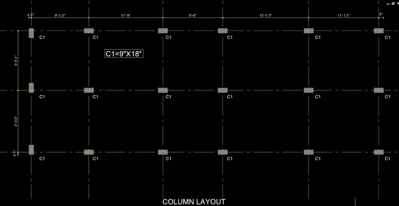
- Select all column from floor plan
- Then create construction line Horizontal and vertical at the center of the rectangle
- Trim to remove excess line
- Text and dimension provide
STEP 8) FOUNDATION LAYOUT
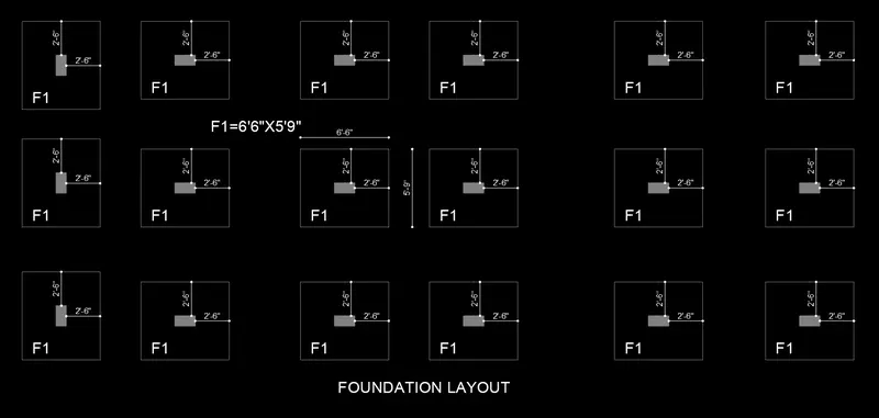
- Copy all column from floor plan
- Then offset for all column at distance 2’6”
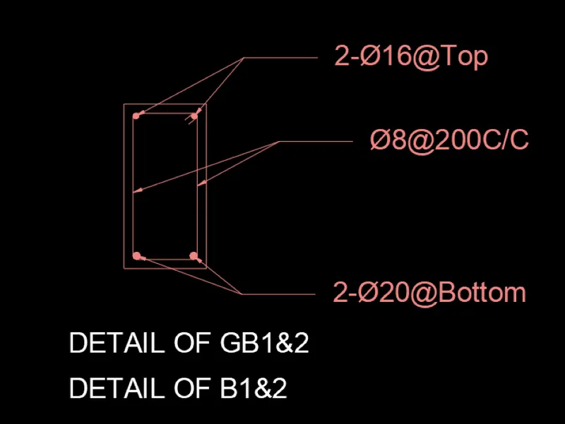
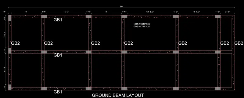
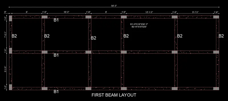
STEP 9) BEAM LAYOUT
- Copy all column from above floor plan
- Create horizontal and vertical line
- Trim and erase to remove unwanted line
STEP 10) RESULT
Follow above procedure and got final result