Project 1 _Creating an Architectural plan for the provided plot size and develop relevant basic structural drawings
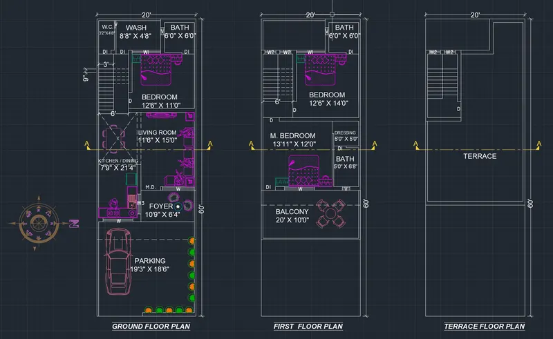
AIM:- To design and draft a layout of residential building for the plot size of {60' x 20'} and also the residential building is "East" facing and then also give all the floor plans, Elevation, Section for the respective plan. And also give the required structural drawings like Column Schedule, Beam, Footing plan etc. And also provide the Door and Window schedule.
PROCEDURE:-
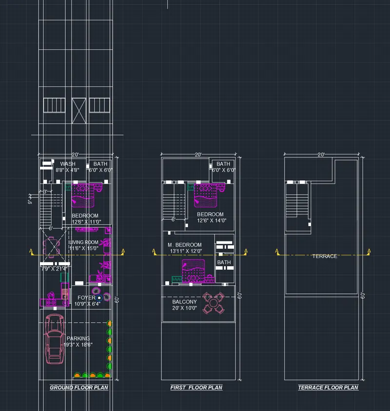
- Draw a plot of {60'X20'} using the command "REC".
- Now explode the rectangle using "X" command.
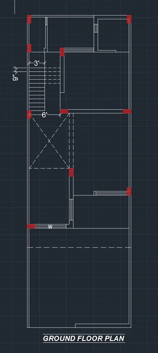
- Now draw a plan according to the vaastu-shastra if possible.
- For drawing the plan use commands like {Line, trim, Extend, Offset etc.}
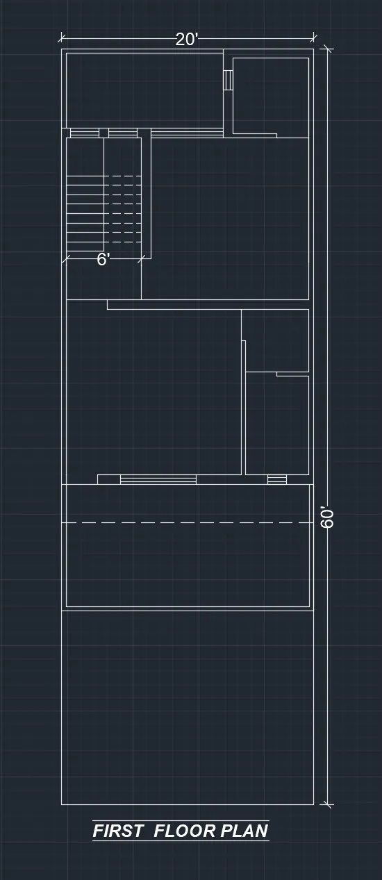
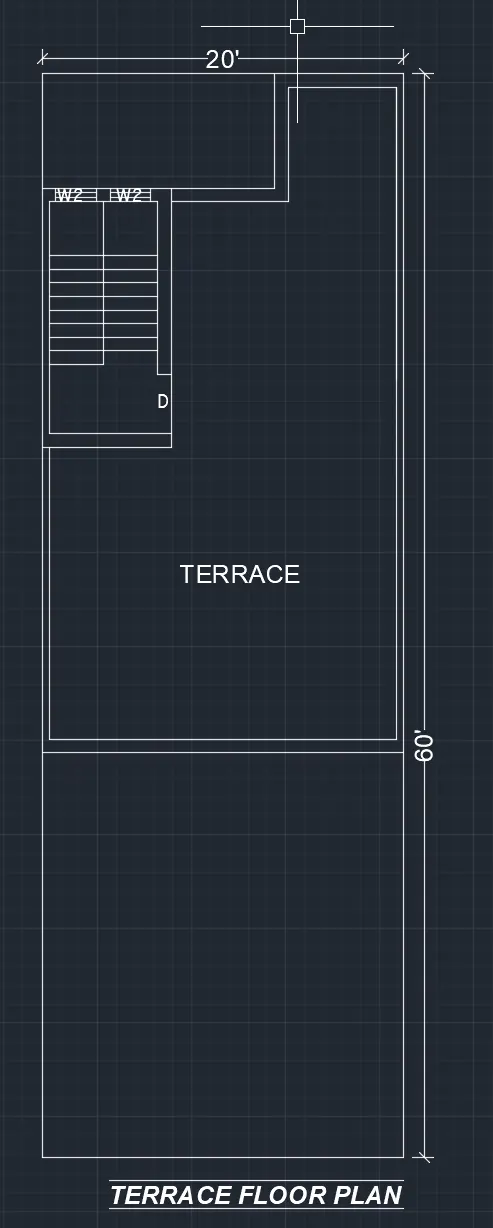
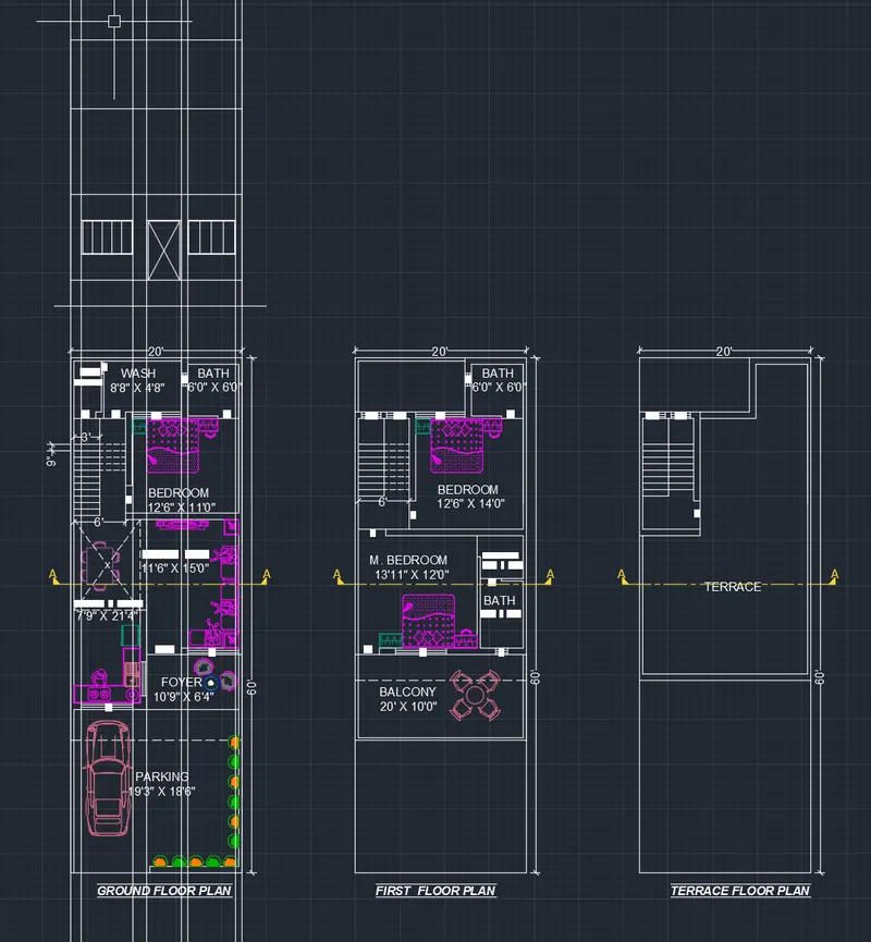
- Now follow the same procedure to draw the First floor plan and Terrace floor plan.
- Now Add the furniture blocks by importing it from another drawing or from downloading online.
- Make sure that the furniture blocks are of different layer from the building plan so it may be easy to differentiate from the drawing.
- Also insert the section line from where the section is going to cut.
- make sure that the section line must be in different layer.
- Also insert the North direction in beside the plan to show the directions of the residential building.
- North direction can be drawn or It's block can be imported.
- Also write down the name and size of the rooms using "DTEXT" command.
- Mention the name of the Doors and Windows as per the size.
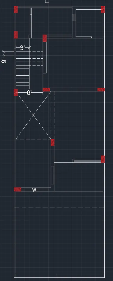
- Now show the position of the columns in the plan and then give the centerline drawing.
- As this drawing is relatively small instead of showing the Grid centerline, The Direct dimention centerline is shown.
- The dimensions are given using "Linear Dimensions" If needed "Aligned dimension" is also used.
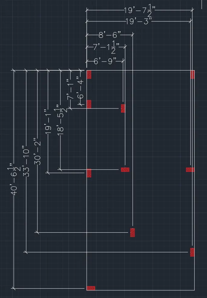
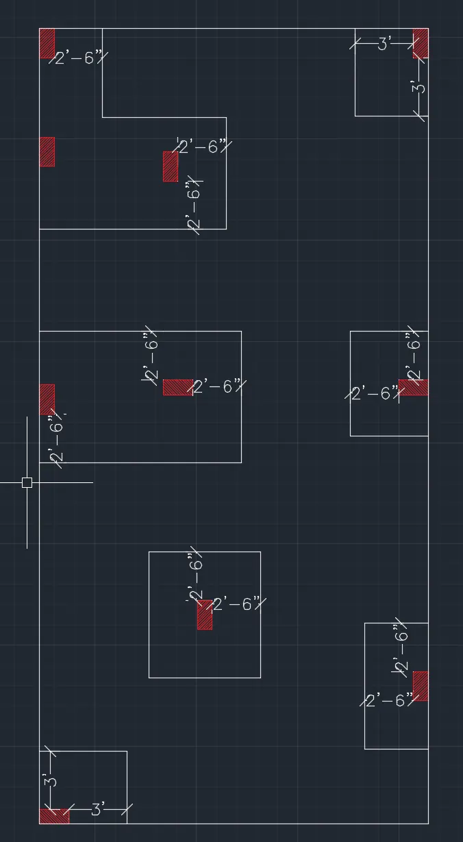
- Now Draw the foundation drawing to show the size of the excavation to be done for the foundation.
- And also show the size of the exacvation by using "Linear Dimension" or "Aligned dimension".
- After foundation layout Column schedule is provided.
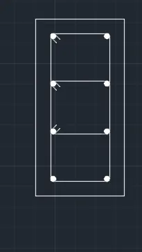
- For column draw a rectangle of 9"X18" by using "REC" command.
- Now give offset of 1.5" (assuming the size of cover provided to reinforcement)to the rectangle inside the rectangle by using command "O"
- Now explode the inner rectangle by using "X" command
- Now give the fillet of the 0.5" to the inner rectangle by using command "F" and then select the fillet radius as 0.5"
- Now draw a circle of 0.5" on both the corners of the inner rectangle in such a way that the boundary of the circle and fillet arc overlaps each other.
- Now select both the circle then enter the command copy "CO" and then select the side quardent point of the circle and then select "array" and then enter the no. of copies as "5" and then select "Fit" and then select upper end of the fillet arc located on the bottom of the rectangle.
- Now add hatch to the circles by using the "Hatch" command and then selecting the type of hatch as solid.
- Now provide the horizontal lines connecting the circles at the quardent point where need.
- Now add lines at 45 degree angle to show the bended strips where needed by using start point as the tangent of the circle.
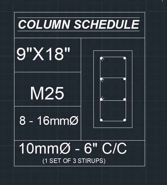
- Now draw a rectangle with the help of "LINE" command of size of 7'X6'.
- Now give the horizontal line the offset of the 1' & 4' respectively to create the three rows.
- Now Give the offset of 2' to the vertical line .
- Now trim horizontal lines in the second columns to create a table for the Scheduling for the column
- Now enter the required data in the boxes using Single line text by "DTEXT" command.
- And move the drawn columns in the respected boxes.
- After Column schedule Beam schedule is provided.
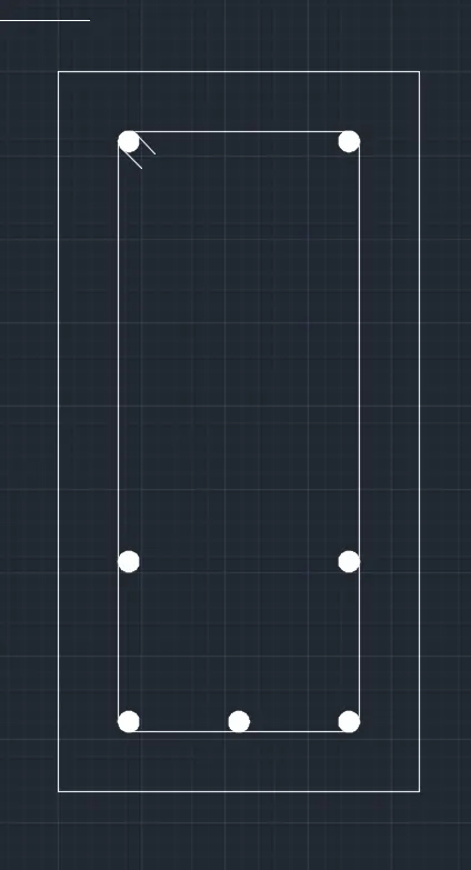
- For Beam draw a rectangle of 9"X18" by using "REC" command.
- Now give offset of 1.5" (assuming the size of cover provided to reinforcement)to the rectangle inside the rectangle by using command "O"
- Now explode the inner rectangle by using "X" command
- Now give the fillet of the 0.5" to the inner rectangle by using command "F" and then select the fillet radius as 0.5"
- Now draw a circle of 0.5" on both the corners of the inner rectangle in such a way that the boundary of the circle and fillet arc overlaps each other.
- Now select both the circle then enter the command copy "CO" and then select the side quardent point of the circle and then select the bottom of the rectangle.
- Now copy one more circle in the bottom-middle and also one copy of each corner circles 6" c/c above them.
- Now add hatch to the circles by using the "Hatch" command and then selecting the type of hatch as solid.
- Now provide the horizontal lines connecting the circles at the quardent point where need.
- Now add lines at 45 degree angle to show the bended strips where needed by using start point as the tangent of the circle.
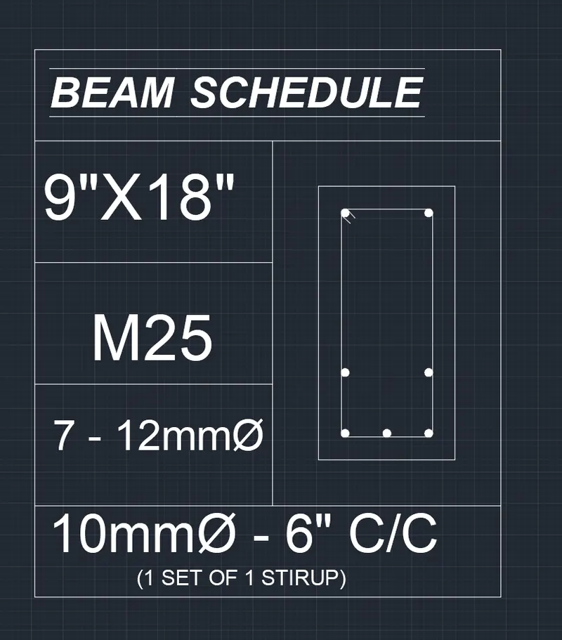
- Now draw a rectangle with the help of "LINE" command of size of 7'X6'.
- Now give the horizontal line the offset of the 1' & 4' respectively to create the three rows.
- Now Give the offset of 2' to the vertical line .
- Now trim horizontal lines in the second beams to create a table for the Scheduling for the beam
- Now enter the required data in the boxes using Single line text by "DTEXT" command.
- And move the drawn beams in the respected boxes.
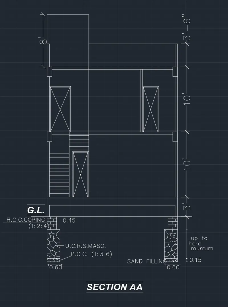
- Now for "SECTION AA" draw a vertical line using command "XLINE".
- Now draw a horizontal base line instersecting the first and last XLINE and name it as "G.L.".
- Now draw the whole section using commands like "LINE", "OFFSET".
- Assume height of the "PLINTH Level" as 3' and all other floors as 10'.
- Height of parapet wall as 3'6".ETC.
- Now after completion of the drawing remove all the XLINE and show the dimensions where needed.
- Show the dimensions in the different layer to differentiate it from the remaining drawing.
- Also add the additional information in the section by inserting blocks of the foundation detail.
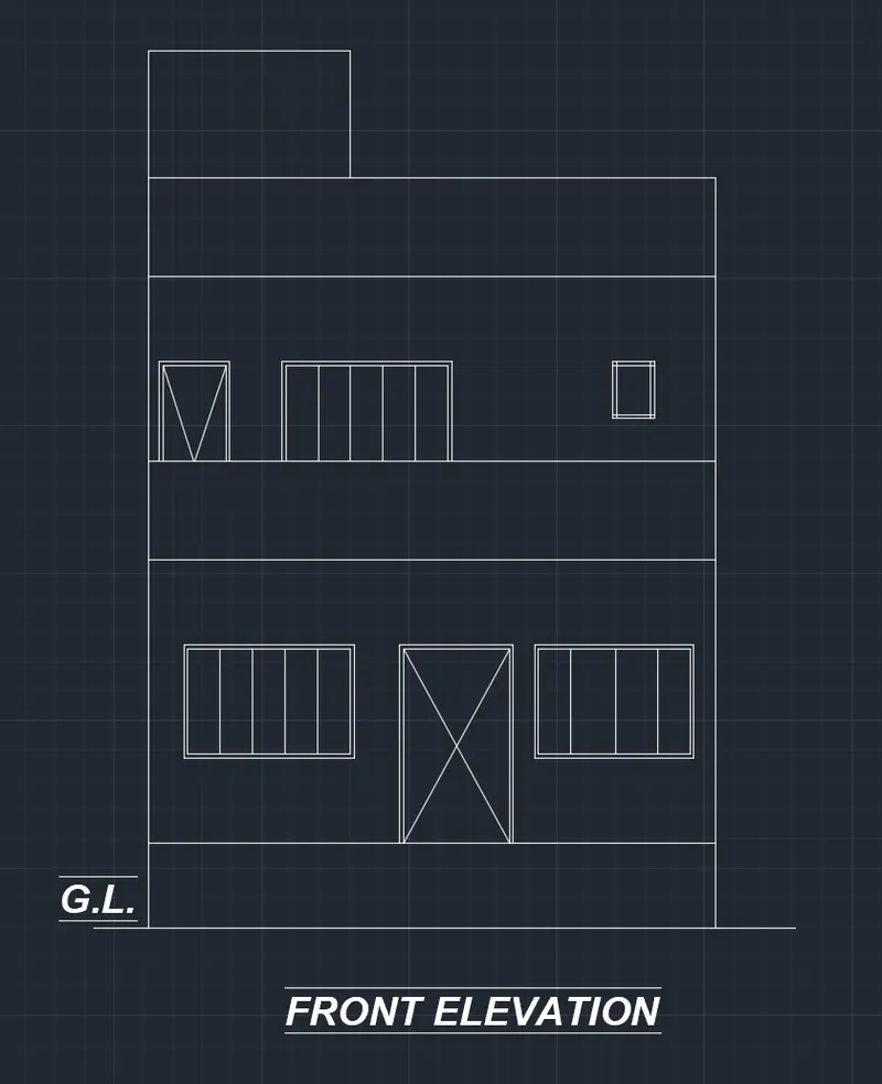
- Now for "ELEVATION" draw a vertical line using command "XLINE".
- Now draw a horizontal base line instersecting the first and last XLINE and name it as "G.L.".
- Now draw the whole section using commands like "LINE", "OFFSET".
- Assume height of the "PLINTH Level" as 3' and all other floors as 10'.
- Height of parapet wall as 3'6".ETC.
- Now after completion of the drawing remove all the XLINE and show the dimensions where needed.
- Show the dimensions in the different layer to differentiate it from the remaining drawing.
- Now Create a Window schedule for the Building plan consisting of Name, Nos., and Size.
- For creating the table enter "TABLE" command.
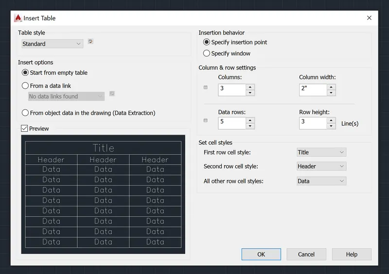
- Now Fill No. of columns as "3"
- Now Fill No. of rows as "5"
- First row cell Type Title
- Second row cell type header
- Then click on OK button and following table will apper.
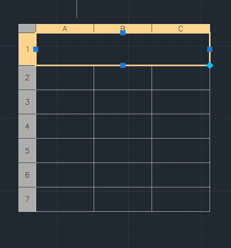
- Now select all the boxes in each column by draging the right-bottom point and the set it to the middle-centre.
- Now enter the given data to complete the given window schedule and adjust the size of the columns as needed.
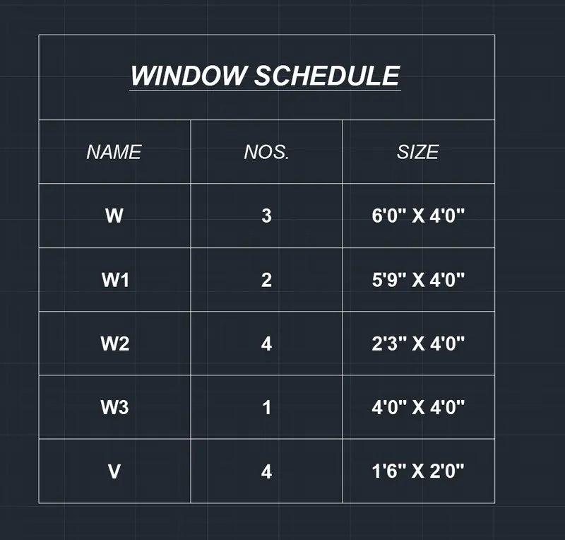
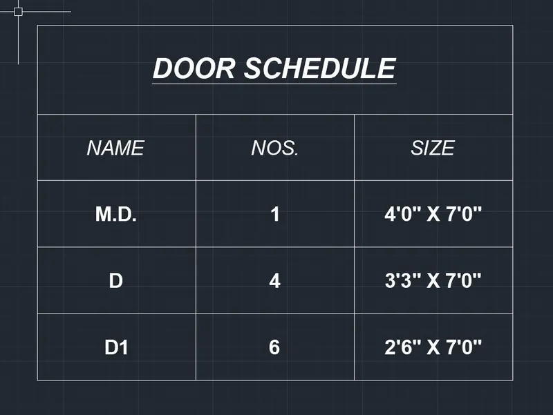
- Now copy the window schedule and change it to the Door Schedule
- Enter the data for the door scheduling and then remove or add rows if needed.