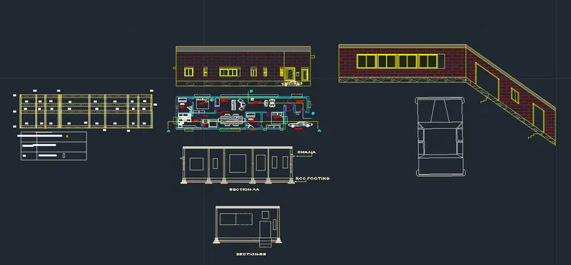
Project 1 _Creating an Architectural plan for the provided plot size and develop relevant basic structural drawings
AIM: To design and draft a layout of a residential building with plot size 18.3m x 6 m
Commands used :
- XL
- Offset
- Trim
- Extension
- Rectangle
- Circle
- Design center
- Line
Procedure to create Architectural Plan
In the command prompt type units and select Decimal
In the insertion scale choose meter
In the command tab type LIM and on the bottom left corner specify 0,0 and for top right specify 100,100
Type zoom and type a i.e zoom all
In the command tab type XL to draft the infinite line
In the command prompt type offset to offset it to the desired distance
In the command tab type trim and remove the extra lines
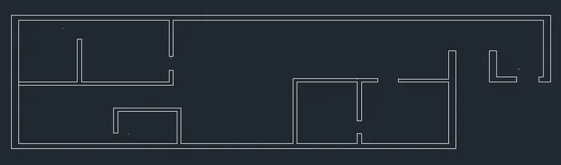
The main entrance in front of which is the car porch is in the east direction as per requirement
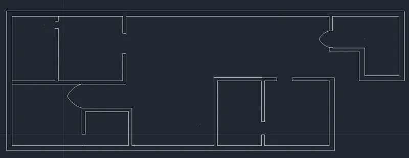
Type TOOLBAR PALLET and select Kitchen and enter the elements of the kitchen required
Next select toilet and enter the necessary elements
Select sofa chairs and entertainment room and place as required
Type DIMSTY in the command bar and rearrange the text lenth precision as per our requirement
Type Text and select the single line text and organize the text length and justification and angle as per necessary
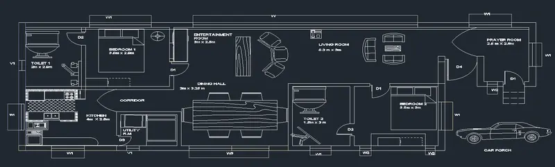
In the ribbon bar select the layer properties and enter all the layers needed
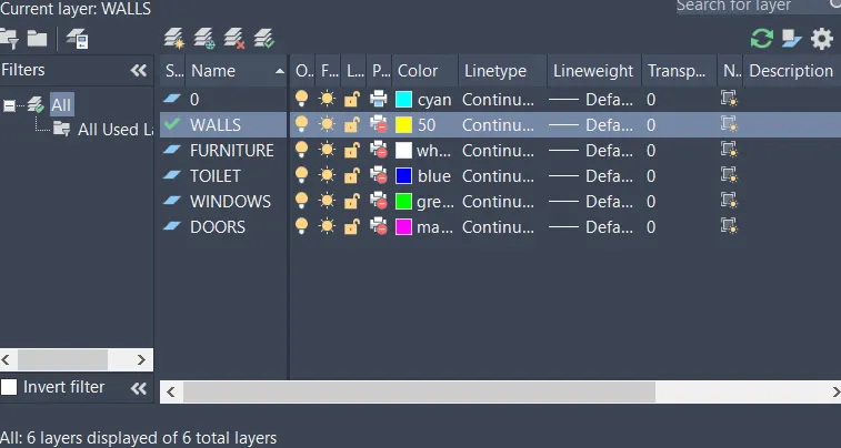
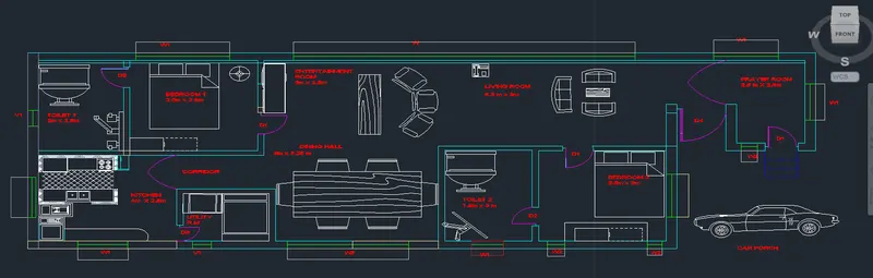
Put all the elements in the layers
FINAL RESULT OF ARCHITECTURAL PLAN
2.Procedure to create elevation
In the command type type L to draft the lines
In the command prompt type hatch then select solid to give the desired annotation and then give colour to the elevation
In the command prompt type ADC ir the design center for car,doors and windows
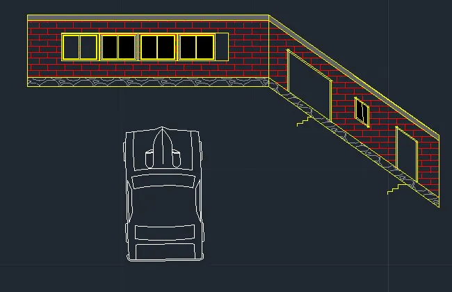
Final result of the elevation
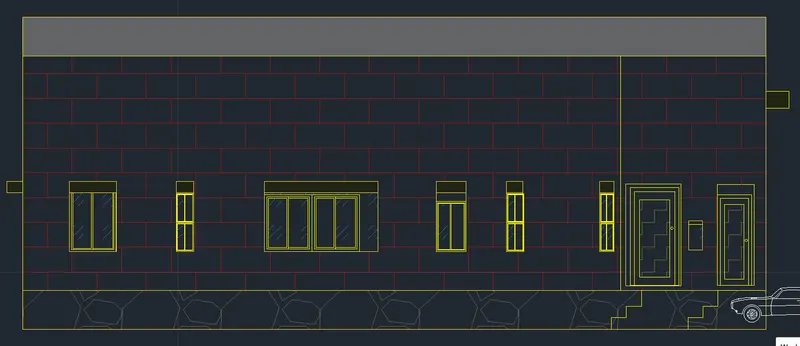
Front and side elevation from the east side
3.Procedure for the sectional drawing
Using the dotted lines in the desired portions to make the sectional drawing
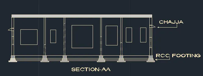
For section-AA
Firstly is the wall and we are cutting through the right so the elements in the wall will be seen and thatswhy we represent it through the dotted line
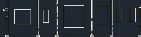
Then is the series of windows
Type DIMSTY in the command bar and rearrange the text lenth precision as per our requirement
When making a sectional drawing we need to include the footing too.
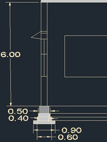
Type Text and select the single line text and organize the text length and justification and angle as per necessary
Result
For section-BB
Firstly is the stair and while cutting the stair in half we will get to see the elemets in the stair so representing it using dotted lines
Then is the door and we are cutting through the right so the elements in the wall will be seen and thatswhy we represent it through the dotted line
Then is the windows
Again windows
When making a sectional drawing we need to include the footing too.
Type DIMSTY in the command bar and rearrange the text lenth precision as per our requirement
Type Text and select the single line text and organize the text length and justification and angle as per necessary
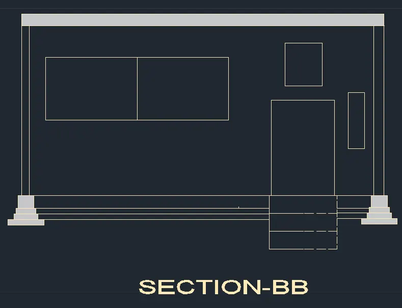
Result
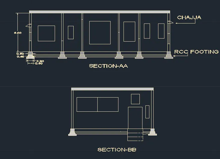
4.Procedure for structural drawing
In the ribbon bar select the layer properties and enter all the layers needed
In the command prompt type XL to darw the grid lines
In the command prompt type LT to get the dotted lines by selecting Continous line 2
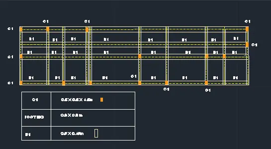
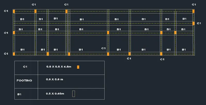
In the command prompt type rec of dimensions 0.5 x 0.5 for columns

In the command prompt type rec of dimensions for footings
Create a circle and write the alphabets and numbers and taking quadrant of the circle as a refrence copy on the grid lines
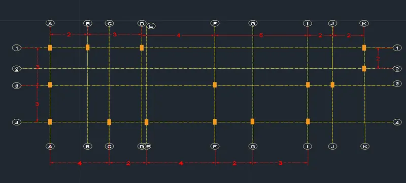
In the command prompt type line to draft the beams
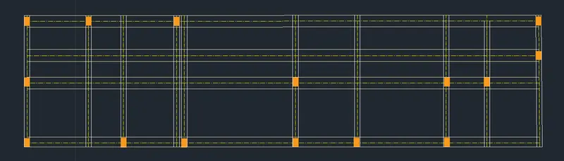
Type DIMSTY in the command bar and rearrange the text lenth precision as per our requirement
Type Text and select the single line text and organize the text length and justification and angle as per necessary
Create a table containing the description of columns footings and beams.
Result
CONCLUSION: