Project 1 _Creating an Architectural plan for the provided plot size and develop relevant basic structural drawings
AIM:
To design and draft a layout of residential building facing east with plot size of 60'x20' with the following details.
- Architectural drawings
- Structural drawings
INTRODUCTION:
XLine: It means construction line. It has infinty edges we used for making wall. By typing "XL" on command line we envoke this tool.
Line: It connects one point to another points. Used to draft various elements.
Trim: This modification tool helps to cut extended edges on the drawing. And to trim inbetween two line or elements. "TR" command to envoke this tool.
Extend: It is also a modification tool, if we have some broken edges or need to extend some portion towards anonther element. "EX" command to envoke the tool.
Offset: Offset the existing element with certain distance. this tool avoid to create new parallel elements.
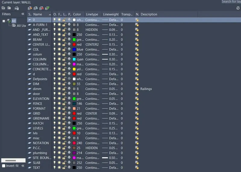
Layer: Each and every elements has unique property and unique style. This layer tool helps to organize those. Line weight, line style, colour gradient, freeze, lock. it has numerous benefits in Auto CAD drafting.
Hatch: Hatching helps to fill the voids with certain texture on it. If we draft wall means, we mention the brickwork details with the help of hatching.
Circle: Used to make circle elements in the sheet. Type "C" to envoke this tool. Here it is used to draft door.
Polygon: Used to make rectangle or polygons with number of sides.
PROCEDURE:
step-1: Type "UN" to select the units we required "Architectural" with precision of 0'-0" and Inches.
step-2: Type "LIMITS" to set the limit of the sheet.
step-3: Type "XL" constrcution line to plot and select "H" and "V" angle to initiate drafting from GROUND FLOOR plan.
step-4: Type "O" to envoke offset tool to offset specify distance of 9" as wall thickness.
step-5: Type "TR" to trim extended edges from construction line.
step-6: Type "F" to envoke fillet tool to fillet the edges with zero radius.
step-7: Type "O" to envoke offset tool to offset specify distance of 4'3" in the direction of +ve X-direction.
step-8: Type "O" to envoke offset tool to offset specify distance of 4.5" in the direction of +ve X-direction.
step-9: Type "O" to envoke offset tool to offset specify distance of 3'6" in the direction of +ve X-direction.
step-10: Type "O" to envoke offset tool to offset specify distance of 4.5" in the direction of +ve X-direction.
step-11: Type "O" to envoke offset tool to offset specify distance of 10' in the direction of +ve Y-direction to make bed room.
step-12: Type "O" to envoke offset tool to offset specify distance of 9" as wall thickness.
step-13: Type "O" to envoke offset tool to offset specify distance of 10' in the direction of +ve Y-direction.
step-14: Type "O" to envoke offset tool to offset specify distance of 4.5" in the direction of +ve Y-direction to create third bed room.
step-15: Type "O" to envoke offset tool to offset specify distance of 6'-7.5" in the direction of -ve Y-direction to draft toilet area.
step-16: Type "O" to envoke offset tool to offset specify distance of 10'0" in the direction of -ve Y-direction to create living room.
step-17: Type "O" to envoke offset tool to offset specify distance of 8'1.5" in the direction of +ve X-direction from the initiall construction line to make living room.
step-18: Type "O" to envoke offset tool to offset specify distance of 4.5" in the direction of +ve X-direction.
step-19: Type "O" to envoke offset tool to offset specify distance of 10' in the direction of +ve Y-direction to make another bedroom.
step-20: Type "O" to envoke offset tool to offset specify distance of 10' in the direction of +ve X direction.
step-21: Type "O" to envoke offset tool to offset specify distance of 6'0" in the direction of +ve X-direction.
step-22: Type "O" to envoke offset tool to offset specify distance of 5'0" in the direction of -ve Y-direction to draft toilet room.
step-23: Type "O" to envoke offset tool to offset specify distance of 9" as wall thickness.
step-24: Type "O" to envoke offset tool to offset specify distance of 11'9" in the direction of +ve X-direction for stair case area.
step-25: Type "O" to envoke offset tool to offset specify distance of 31'1.5" in the direction of -ve y-direction.
step-26: Type "O" to envoke offset tool to offset specify distance of 20' in the direction of +ve X-direction
step-27: Assume the columns occuring location in architectural drawing.
step-28: Type "PL" to plot septic tank and sump for this house hold as per housing planning and department.
step-29: Type "DT" to select left justify with text height of 300 mm and text angle of zero degree and now enter the text.
step-30: Type "CO" copy the text and paste it wherever it is required in the floor plan.
step-31: Type "ED" to edit the text and mention the name of all rooms.
step-32: Type "DIML" dimlinear to mark the dimensions of floor plan.
step-33: Type "DIMC" dimcontinue tool to mark all dimensions of a room.
step-34: Type "DT" to select left justify with text height of 1' and text angle of zero degree and now enter the text.
step-35: Type "LT" to open Line style dialogue box and load center line tool to draw section view of the ground floor plan.
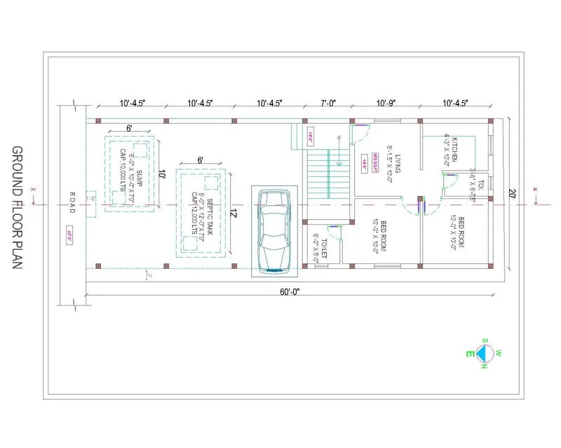
step-36: Type "CO" to copy all the objects from the ground floor like wall and rooms and staircase details for drafting FIRST FLOOR PLAN.
step-37: Type "ERASE" septic tank and sump and vehicle objects.
step-38: Type "O" to envoke offset tool to offset specify distance of 4'3" in the direction of +ve X-direction.
step-39: Type "O" to envoke offset tool to offset specify distance of 10' in the direction of -ve Y-direction.
step-40: Type "O" to envoke offset tool to offset specify distance of 4.5'' in the direction of +ve X-direction.
step-41: Type "O" to envoke offset tool to offset specify distance of 7'6" in the direction of +ve X-direction.
step-42: Type "O" to envoke offset tool to offset specify distance of 10' in the direction of -ve Y-direction.
step-43: Type "O" to envoke offset tool to offset specify distance of 3' in the direction of +ve X-direction.
step-44: Type "O" to envoke offset tool to offset specify distance of 10' in the direction of -ve Y-direction to create balcony portion.
step-45: Type "O" to envoke offset tool to offset specify distance of 8'10.5'' in the direction of +ve X-direction.
step-46: Type "O" to envoke offset tool to offset specify distance of 3'6'' in the direction of +ve X-direction.
step-47: Type "O" to envoke offset tool to offset specify distance of 6'7.5" in the direction of -ve Y-direction to create toilet portion.
step-48: Type "O" to envoke offset tool to offset specify distance of 3' in the direction of +ve X-direction to draft corridor
step-49: Type "O" to envoke offset tool to offset specify distance of 7'1.5'' in the direction of +ve X-direction.
step-50: Type "O" to envoke offset tool to offset specify distance of 10'0'' in the direction of -ve Y-direction.
step-51: Type "O" to envoke offset tool to offset specify distance of 3'6'' in the direction of +ve X-direction.
step-52: Type "O" to envoke offset tool to offset specify distance of 7'0'' in the direction of -ve Y-direction.
step-53: Type "O" to envoke offset tool to offset specify distance of 7'1.5" in the direction of +ve X-direction.
step-54: Type "O" to envoke offset tool to offset specify distance of 10' in the direction of -ve Y-direction.
step-55: Type "O" to envoke offset tool to offset specify distance of 9'6" as front balcony.
step-56: Type "O" to envoke offset tool to offset specify distance of 3'0" in the direction of -ve Y-direction.
step-57: Type "DT" to select left justify with text height of 300 mm and text angle of zero degree and now enter the text.
step-58: Type "CO" copy the text and paste it wherever it is required in the floor plan.
step-59: Type "ED" to edit the text and mention the name of all rooms.
step-60: Type "DIML" dimlinear to mark the dimensions of floor plan.
step-61: Type "DIMC" dimcontinue tool to mark all dimensions of a room.
step-62: Type "DT" to select left justify with text height of 1' and text angle of zero degree and now enter the text.
step-63: Type "LT" to open Line style dialogue box and load center line tool to draw section view of the first floor plan.
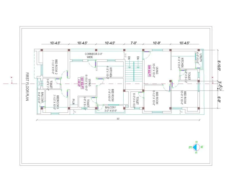
step-64: Type "CO" to copy all the objects from the first floor like wall and rooms and staircase details for drafting SECOND FLOOR PLAN.
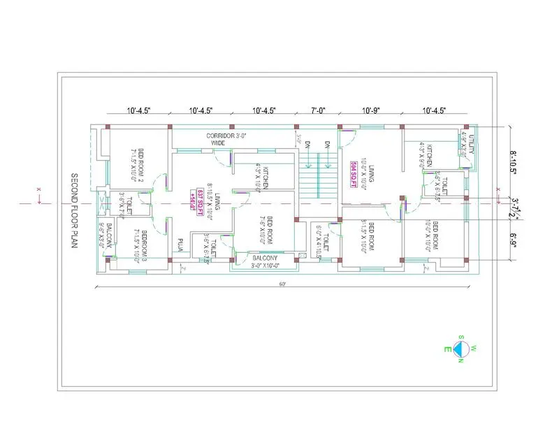
step-65: Type "CO" to copy all the objects from the first floor like wall and rooms and staircase details for drafting TERRACE FLOOR PLAN.
step-66: Type "ERASE" all the rooms and objects we copy except wall and draft water tank area and stair case head room.
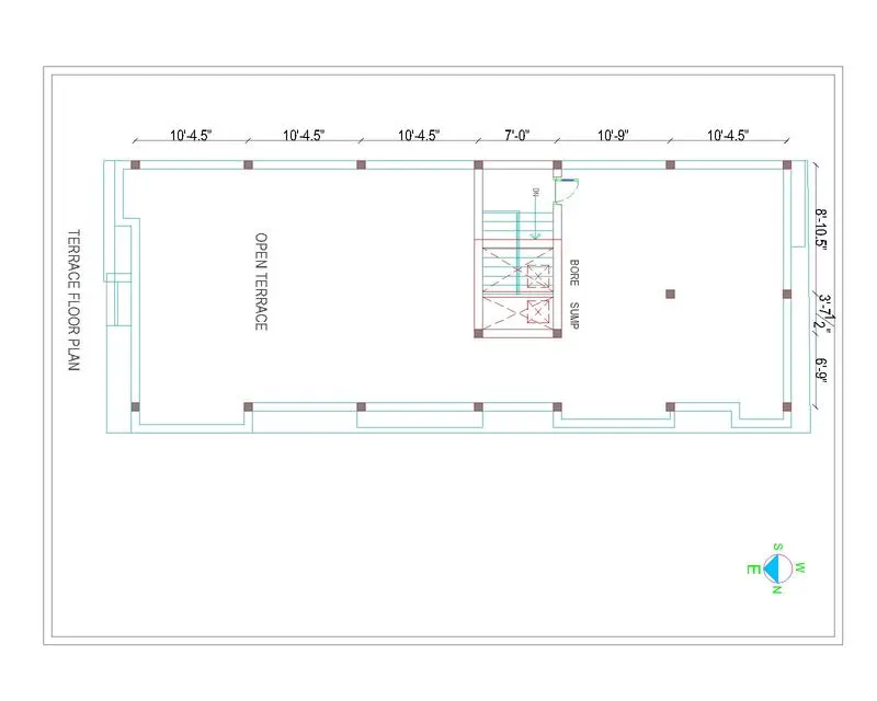
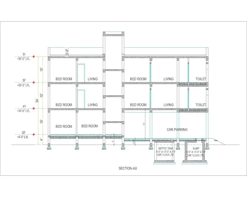
step-67: Type "XL" constrcution line to plot and select H to plot Horizontal lines with the reference from floor plan to draft section view.
step-68: Type "TR" trim the extended lines from the drawing.
step-69: Type "O" to 9" thick R.C.C. come P.C.C. for septic tank.
step-70: Type "O" to 7'0" depth to create septic tank.
step-71: Type "O" to 12'0" width to create septic tank.
step-72: Type "O" to 6'0" breadth to create septic tank.
step-73: Type "O" to 9" thick R.C.C. come P.C.C. for sump.
step-74: Type "O" to 7'0" depth to create sump.
step-75: Type "O" to 6'0" width to create sump.
step-76: Type "O" to 10'0" width to create sump.
step-77: Type "O" to 9" thick R.C.C. come P.C.C. for septic tank.
step-78: Type "O" to 7'0" depth to create septic tank.
step-79: Type "O" to 12'0" width to create septic tank.
step-80: Type "O" to 6'0" breadth to create septic tank.
step-81: Type "O" to 9" thick R.C.C. come P.C.C. for footing.
step-82: Type "L" to to draft isolated footing in the sectional drawing.
step-83: Type "O" to 4'0" above from ground to floor level
step-84: Type "H" hatch P.C.C. and R.C.C. area.
step-85: Type "O" to 10'0" to draft first floor slab level.
step-86: Type "O" to 5" depth of slab.
step-87: Type "O" to 5' to draft staircase landing slab.
step-88: Type "CO" to first floor level to paste it another remaining areas.
step-89: Type "DIML" dimlinear to mark the dimensions of sectional view.
step-90: Type "DIMC" dimcontinue tool to mark all dimensions of a room.
step-91: Type "DT" to select left justify with text height of 1' and text angle of zero degree and now enter the text.
step-92: Type "H" hatch P.C.C. and R.C.C. area.
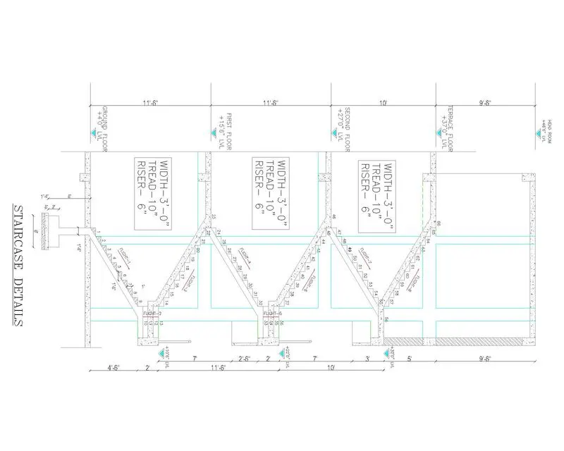
step-93: Type "XL" constrcution line to plot and select H to plot Horizontal lines with the reference from floor plan.
step-94: Type "TR" trim the extended lines from the drawing.
step-95: Type "PL" to plot staircase tread and rise with the distance of 10" and 6" respectively up to the mid level of floot.
step-96: Type "PL" to plot staircase tread and rise with the distance of 10" and 6" respectively up to bottom of the first floor slab.
step-97: Type "CO" to ground floor stair case objects into first floor and remaining floor.
step-98: Type "O" to 9'6" to draft stair case head room.
step-99: Type "O" to 5" thick R.C.C.
step-100: Type "DIML" dimlinear to mark the dimensions of sectional view.
step-101: Type "DIMC" dimcontinue tool to mark all dimensions of a room.
step-102: Type "DT" to select left justify with text height of 1' and text angle of zero degree and now enter the text.
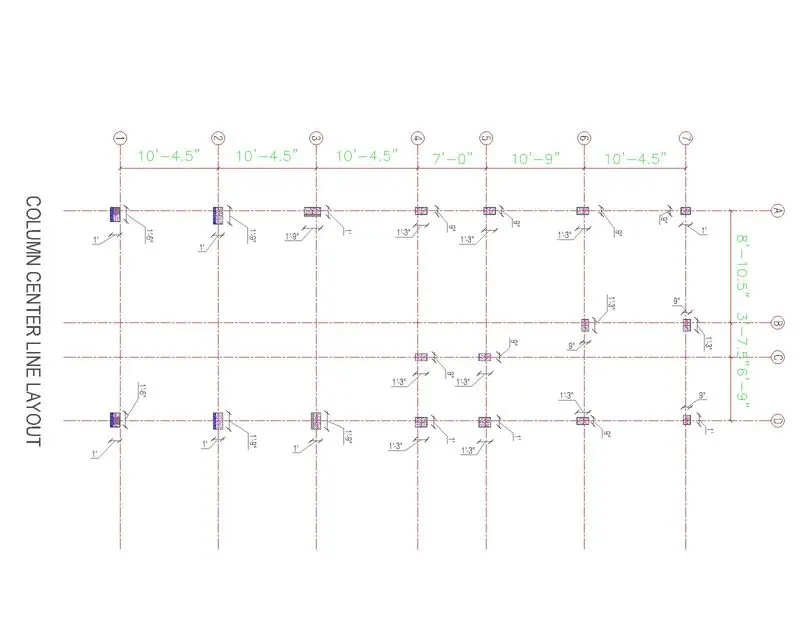
step-103: Type "POLYGON" with four sides to plot column of the residential building.
step-104: Type "H" hatch the column concrete.
step-105: Type "B" block the column objects.
step-106: Type "CO" copy the column object and paste into required position.
step-107: Type "DIML" dimlinear to mark the dimensions.
step-108: Type "DIMC" dimcontinue tool to mark all dimensions of a room.
step-109: Type "DT" to select left justify with text height of 1' and text angle of zero degree and now enter the text.
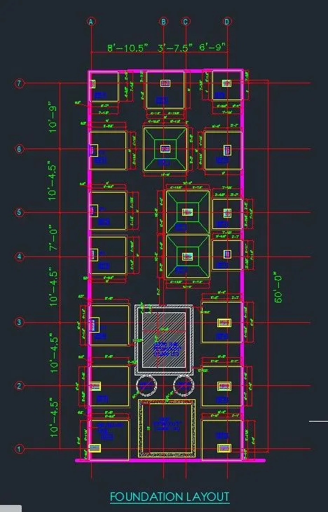
step-110: Type "CO" to copy the column center line layout and paste it to draft footing layout.
step-111: Type "L" line tool to draft footing plan.
step-112: From the basis of analysis to calculate footing dimensions.
step-113: Type "PL" to draft remaining all footings.
step-114: Type "DIML" dimlinear to mark the dimensions.
step-115: Type "DIMC" dimcontinue tool to mark all dimensions of a room.
step-116: Type "DT" to select left justify with text height of 1' and text angle of zero degree and now enter the text.
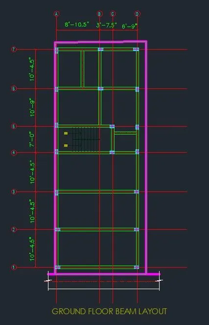
step-117: Type "CO" to copy the ground floor plan and paste it to draft Ground floor beam layout.
step-118: Type "L" line tool to draft beams in ground floor.
step-119: From the basis of analysis to calculate beam dimensions.
step-120: Type "L" to draft remaining all beam span.
step-121: Type "DIML" dimlinear to mark the dimensions.
step-122: Type "DIMC" dimcontinue tool to mark all dimensions of a room.
step-123: Type "DT" to select left justify with text height of 1' and text angle of zero degree and now enter the text.
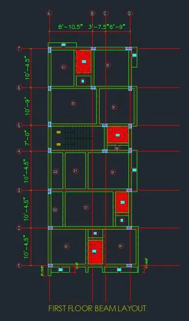
step-124: Type "CO" to copy the first floor plan and paste it to draft First floor beam layout.
step-125: Type "L" line tool to draft beams in first floor.
step-126: From the basis of analysis to calculate beam dimensions.
step-127: Type "L" to draft remaining all beam span.
step-128: Type "H" to hatch shunken slab.
step-129: Type "DIML" dimlinear to mark the dimensions.
step-130: Type "DIMC" dimcontinue tool to mark all dimensions of a room.
step-131: Type "DT" to select left justify with text height of 1' and text angle of zero degree and now enter the text.
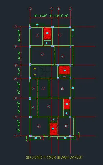
step-132: Type "CO" to copy the second floor plan and paste it to draft Second floor beam layout.
step-133: Type "L" line tool to draft beams in second floor.
step-134: From the basis of analysis to calculate beam dimensions.
step-135: Type "L" to draft remaining all beam span.
step-136: Type "H" to hatch shunken slab.
step-137: Type "DIML" dimlinear to mark the dimensions.
step-138: Type "DIMC" dimcontinue tool to mark all dimensions of a room.
step-139: Type "DT" to select left justify with text height of 1' and text angle of zero degree and now enter the text.
step-140: Type "CO" to copy the terrace floor plan and paste it to draft Terrace floor beam layout.
step-141: Type "L" line tool to draft beams in terrace floor.
step-142: From the basis of analysis to calculate beam dimensions.
step-143: Type "L" to draft remaining all beam span.
step-144: Type "DIML" dimlinear to mark the dimensions.
step-145: Type "DIMC" dimcontinue tool to mark all dimensions of a room.
step-146: Type "DT" to select left justify with text height of 1' and text angle of zero degree and now enter the text.
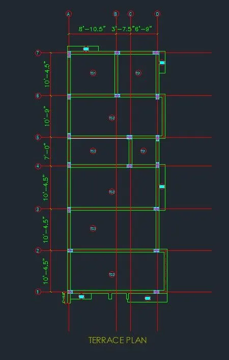
step-147: Type "CO" to copy the terrace floor plan and paste it to draft Water Tank beam layout.
step-148: Type "L" line tool to draft beams in above the terrace floor plan.
step-149: From the basis of analysis to calculate beam dimensions.
step-150: Type "L" to draft remaining all beam span.
step-151: Type "DIML" dimlinear to mark the dimensions.
step-152: Type "DIMC" dimcontinue tool to mark all dimensions of a room.
step-153: Type "DT" to select left justify with text height of 1' and text angle of zero degree and now enter the text.
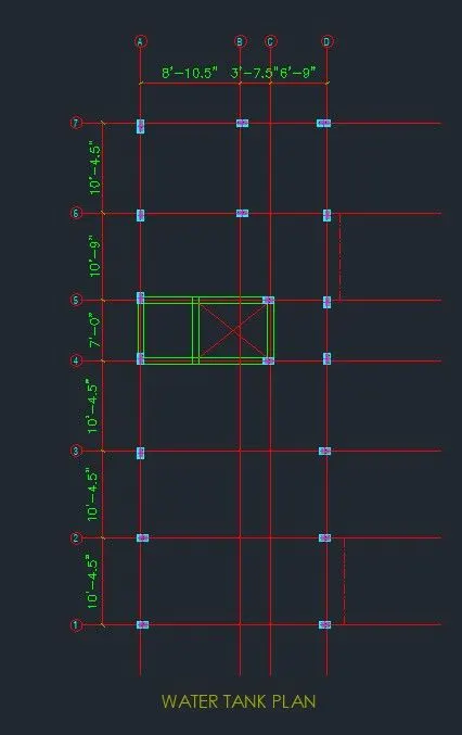
RESULT:
Architectural plan and Structural drawing of Residential building drawn by using Auto CAD software.
Ground Floor Plan:
First Floor Plan:
Second Floor Plan:
Terrace Floor Plan:
Sectional View:
Secional View (Stair case details):
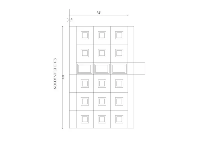
Structural Drawings:
Column center line layout:
Footing layout:
Ground Floor Beam layout:
First Floor Beam layout:
Second Floor Beam layout:
Terrace Floor Beam layout:
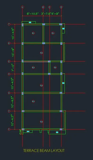
Water Tank Beam layout: