Project 1 _Creating an Architectural plan for the provided plot size and develop relevant basic structural drawings
ANS 1.
AIM :-
The Aim of the project is to create
1.An Architectural Plan
2.Structural Plan
of the given plot size using Autocad software.
INTRODUCTION :-
Using Autocad software to create the Figure and also using different tools such as xline , line , dimension , mtext , lines etc to draft.
PROCEDURE :-
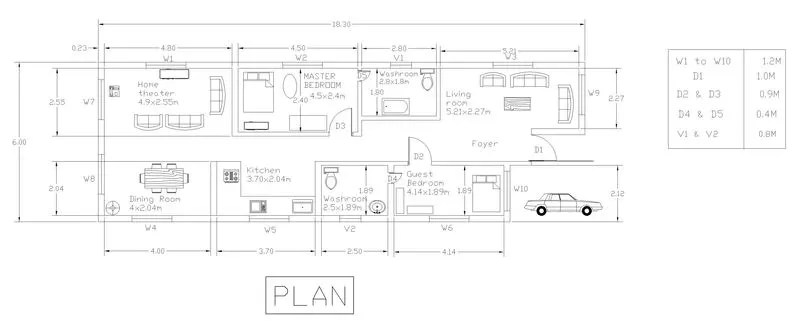
ARCHITECTURAL PLAN
1.Open Autocad and then do the following setting first
a.Type Units command and select unit as meters.
b.Type Limmax and enter values as 100,100.
c.Type Zoom command and enter 'a'.
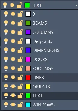
2.After completing the following steps , lets draw architectural view
a.Type XL and draw two infinite lines one in horizontal direction and other in vertical direction.
b.Now,Use offset tool and offset 18.3 from vertical line and 6 from horizontal line.
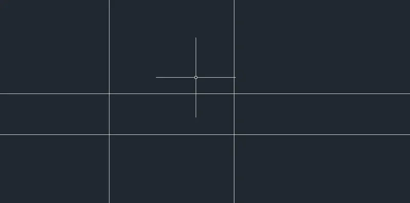
c.Trim the edges.

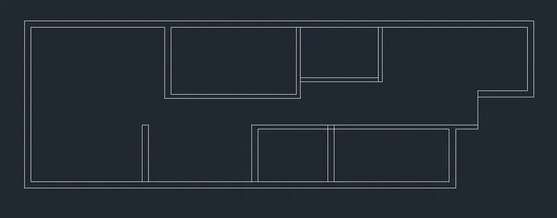
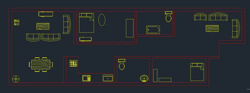
d.After that, select your size for different rooms and then select offset tool and do the offsetting.
e.Select offset and offset 0.23 from vertical line , 4.8 from 0.23 line , 0.23 from 4.8 line ,4.5 from 0.23 line , 0.15 from 4.5 line , 2.8 from 0.15 line , 0.15 from 2.8 line , 5.2 from 0.15 line.
f. Now,again trim and offset from Horizontal line and offset 0.23 from bottom line , 1.9 from 0.23 line , 0.15 from 1.9 line,1 from 0.15 line , 0.15 from 1 line.
g Trim extra lines.
Now Open ADC to place the different objects in the respective rooms.
and also draw the windows and doors wherever provided
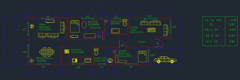
D1 = 1.0M
D2 & D3 = 0.9M
D4 & D5 = 0.4M
W1 to W10 = 1.5M
V1 & V2 = 0.8M
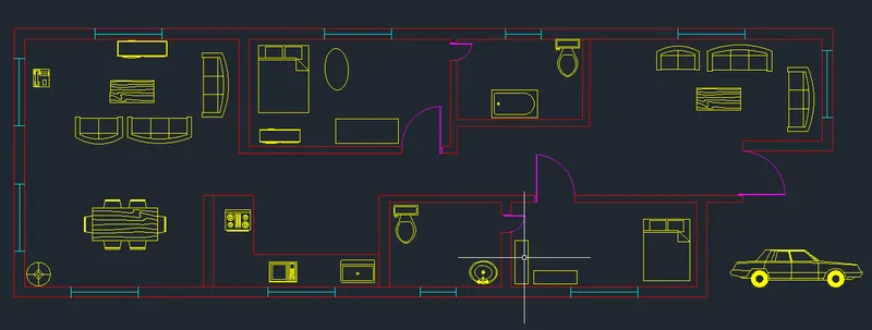
Now write the texts and dimension the drawn figure.
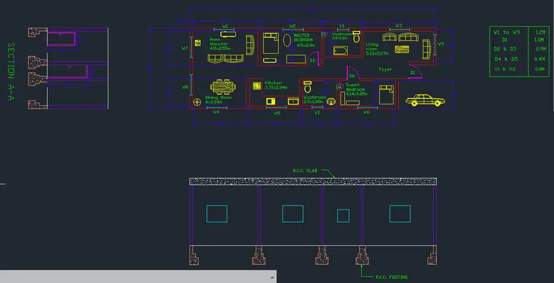
Architectural Plan :-
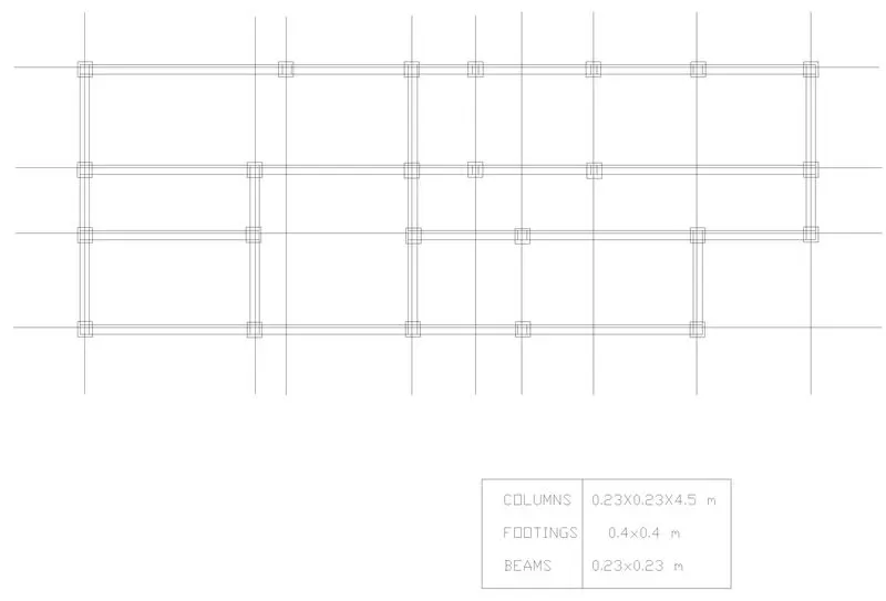
2.STRUCTURAL PLAN :-
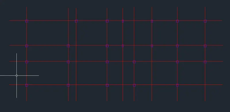
For structural plan :-
Step1
a.Draw the xlines using xline command for the grid lines.
b.Now draw columns of size 0.23x0.23m by selecting rectangle .
c.Connect and trim extra lines.
d.Put every unit in proper layers.
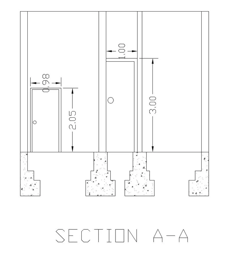
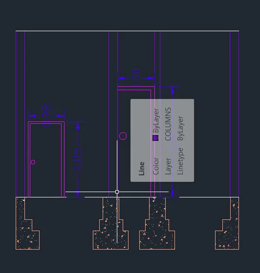
Now for section AA
Section AA is the portion section from architectural view.
a.Project the colum lines using line tool.
b. Draw the doors as per the mentioned dimensions.
c. Draw the footing using the line tool.
d. Place different objects in proper layer.
e.Trim unwanted lines.
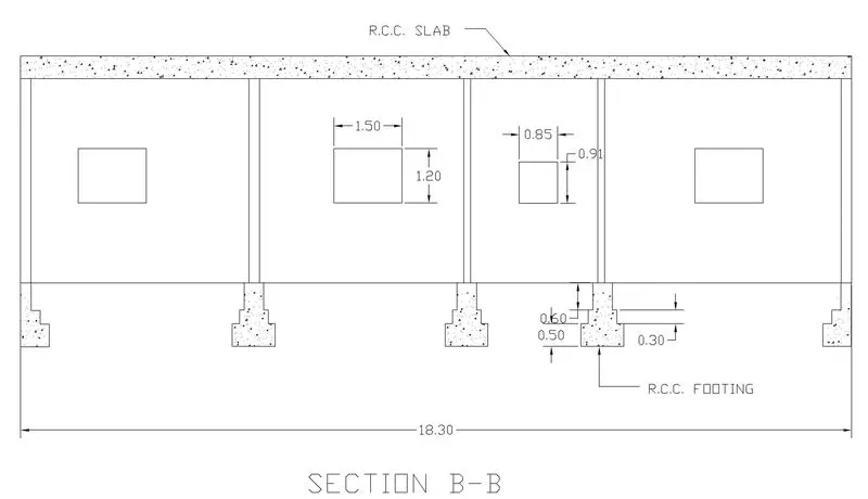
For section BB
For Section BB same steps are to be followed as per section AA.
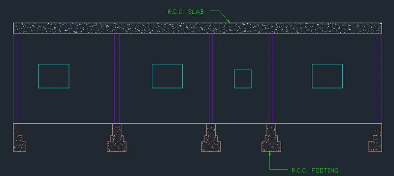
HENCE, CREATED SECTION AA AND SECTION BB is attached below
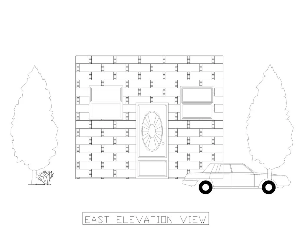
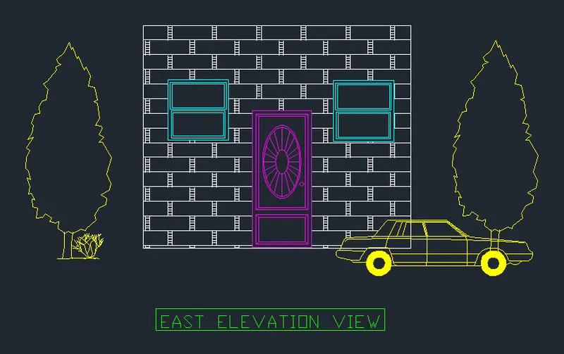
ELEVATION:-
1. Select line tool and draw line .
2. Place the doors and windows as per the elevational view from the architectural figure.
3.Type ADC to place the different objects and select door , windows ,trees , bushes , car .
4.Hatch the figure using Hatch command
5.Place every object in their respective layers
RESULT :-
Created figure is attached below -