Project 1 _Creating an Architectural plan for the provided plot size and develop relevant basic structural drawings
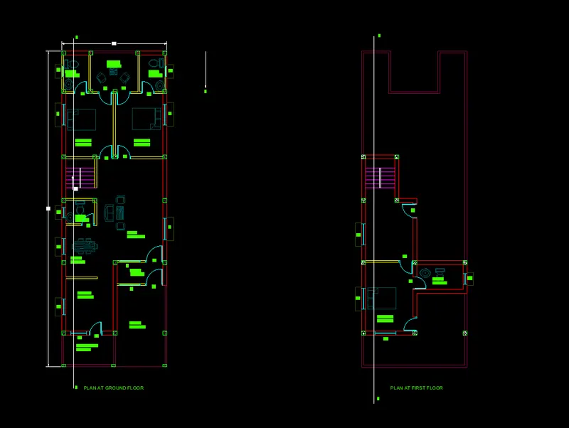
Aim: To create the archtectural plan for the 60' x 20' plot size and develop the drawinsgs like column, beam and footing plan.
Introduction:
The architectural drawing is a technical drawing that used to develop a design idea into a coherent proposal, to communicate ideas and concepts to convience clients of the merits of a design, to assist building contractor to construct based on the design intent. architectural drawings are made acoording to a set of conventions, which includes particular views (Floor, plan, section etc), sheet size, units of the measurment, and scales, annotation and cross referring.
- Floor Plan: A floor plan is a fundamental architectural drawing, a view from the above showing the arrangement of the spaces in a building in the same way as a map. but showing the arrangements of a at particular level of the building. Technically it is the horizontal section cut through the building, showing the walls, windows, and door openings.and other feature at that level. the plan view includes anything that could be seen below the levels, floors, stair and sometimes furniture.
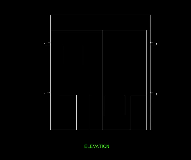
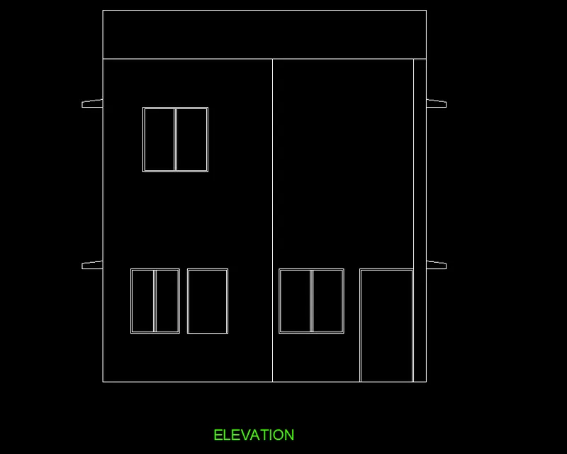
- Elevation: An elevation is a view of building seen from one side, a flat representation of of one facade. this is the most common view used to described the external appearance of the building. Buildings are simple rectangular shape in the plan, so typically the elevation may show the all parts of the buildings that are seen from the particular direction.
- Cross Section: A cross section is also simply called as sections, represents a vertical plane cut through the object in the same way as floor plan is the horizontal section viewed from the top. in the section view everything is cut by a section plane is shown in the bold line often with the solid fikl to show the object thatb are cut through, and anything seen beyond that line shwn in thin line. sections are used to described the relation between different levels of the buildings.
A structural drawing is a type of engineering drawing is a plan or set of plans and details for how the buildings or other structures are built. structural drawings are generally prepared by registred profesional engineers. and based on the information provided by the architectural drawings are primarly concern with the load carrying the members of a structure. they outline size and types of the materials to be used as well as the general demands for the connections. they do not address the architectural details like surface finishes, partition walls etc. the structural drawings commuicate the design of the building structure to the building authority for the review. structural drawing also included with the proposed building contract documents, which guide contractors in detailing, fabricating, and installing the parts of the structures. the structural drawings are used to progress the the architect concept by specifying the shape and position of the all parts of the structure on site. Structural drawings are used to for the preparation of the reinforcemets details. structural drawings are typically includes setting out dimensions for the concrete structures on the site, plans, sections and elevations showing the layout, dimensions and levels of the all concrete members within the structures, location of the all holes, chases, pockets, fixing and other items affecting the concreting the work. notes onn the specification, finishes and all cross references affecting the construction.
Commands used for drawings:
- Unit command
- limit command
- Xline
- Line command
- Offset
- Copy
- Move
- Mirror
- Trim
- Block
- Insert
- Dim linear
- Dimcontinuous
- Dtext
- Bedit
- layer
- Rectangle command
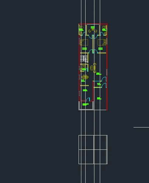
Drawing of the floor plan
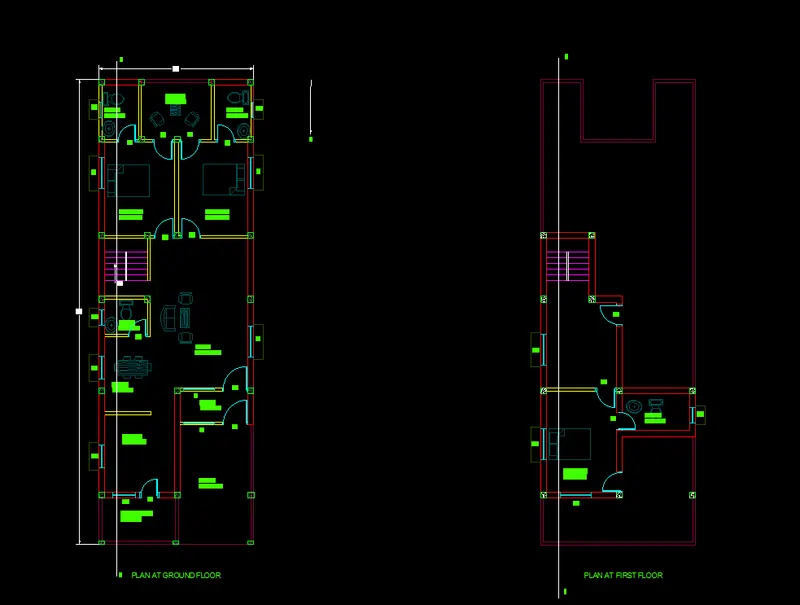
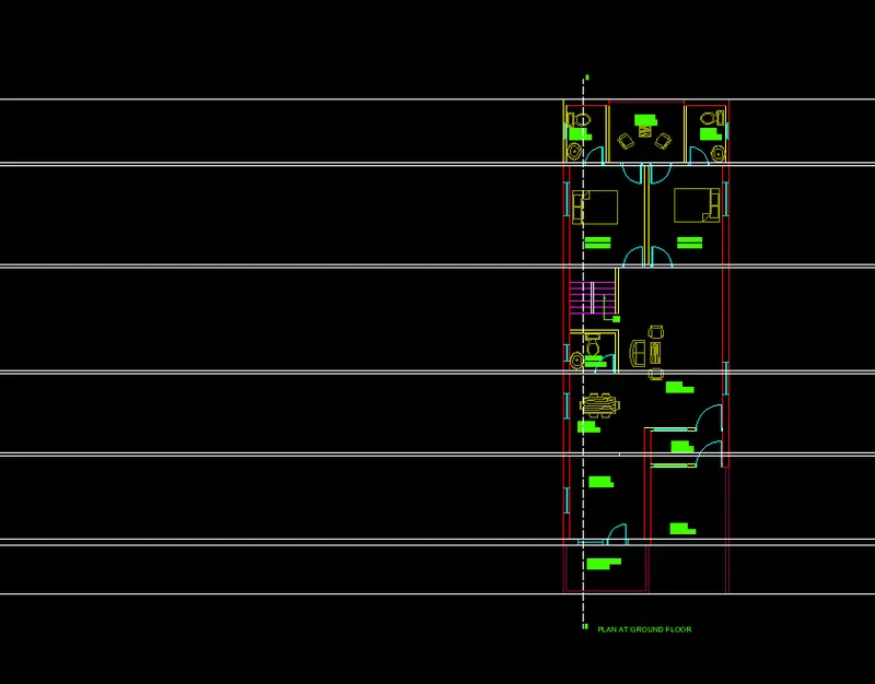
- Open the new autocad sheet select the imperial.
- Un enter and select the engineering the select the precision.
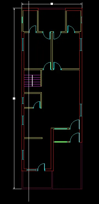
- Type the Xline enter draw horizontal and vertical lines.
- Offset the horizontal line and vertical line by 9" and offset horizontal line by 10' and offset it by 4.5".
- Offset the vertical line by 9' and offset this line by 9".
- offset the horizontal line by a offset distance of 9'8", 4.5", 4'6", 4.5", 7'6", 4.5", 12", 4.5", 7' and 9" respectively.
- offset the toilet room vrtical line by 4.5".
- offset the vertical line of toilet by a 4'9", 4.5", 9', 4.5", 4'9" and 4.5" respectively.
- Offset the bedroom vertcal line by 12', 4.5" and 12' and 9" respectively.
- the bottom horizontal outer line of the kitchen is offseted by a offsst distance of 5'7" and 4.5" respectively.
- offset the bottom line bedrrom by 19'4" , 4.5", 4' and 4.5" respectively.
- Trim the all unwanted lines.
- Trim the door openings.
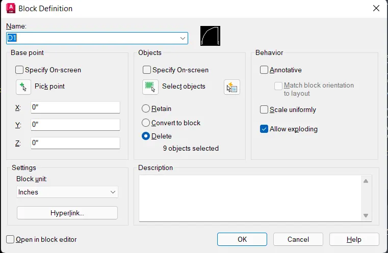
- Sizes of the door
D1 = 3'4" x 7'
D2 = 2'8" x 7'
D3 = 2'6" x 7'
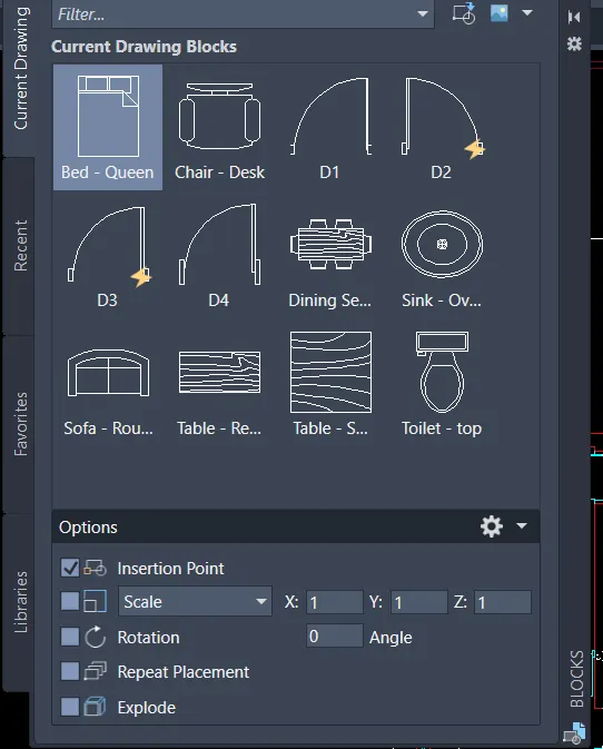
- Door block is created and inserted in the required position.
- Sizes of the windows
W = 4' x 4'
W1 = 3' x 4'
w2 = 2' x 2'
- window block is created and it is inserted at the required position.
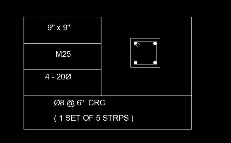
- column of 9" x 9" is created and placed at the required position.
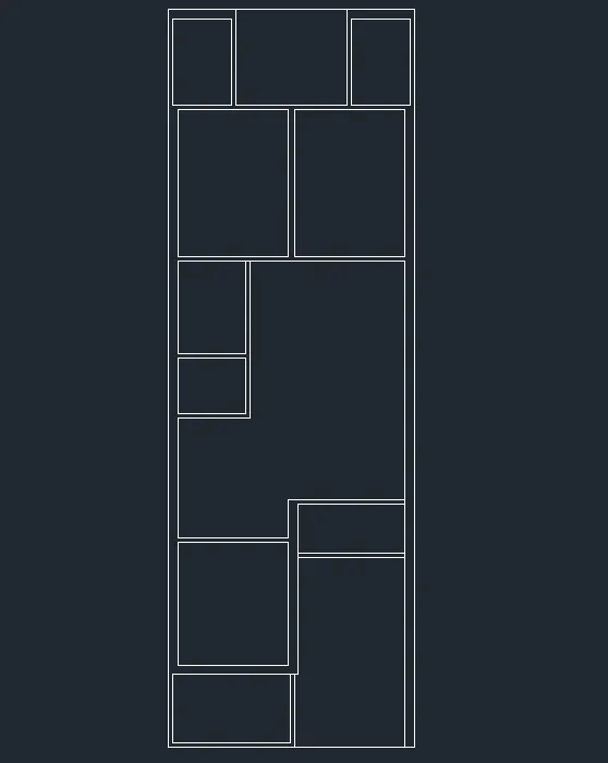
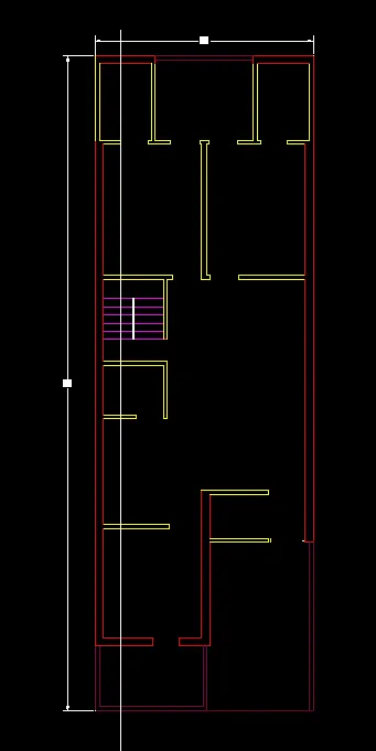
- By using the Xline the the horizontal and vertical line is created.
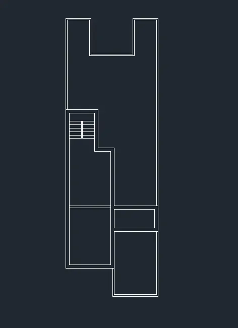
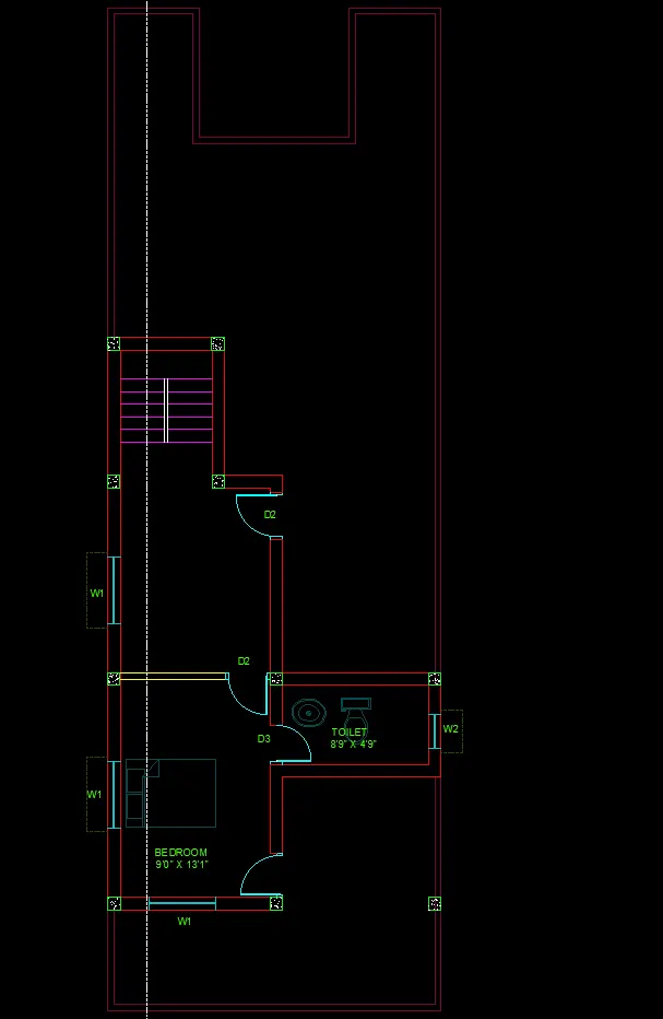
- offset the horizontal line by 9", 13'1", 9", 19'4" and 9" respectively.
- Offset the vertical line by 9", 9'0", 9", 8'9" and 9" respectively.
- Trim the unwanted lines.
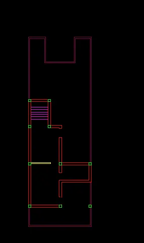
- from the top line of the bedroom offset it by 9", 4'9" and 9" respectively.
- trim the all unwanted lines.
- Trim the door openings.
- by using the insert option the door is positioned.
- Column are placed at the required position.
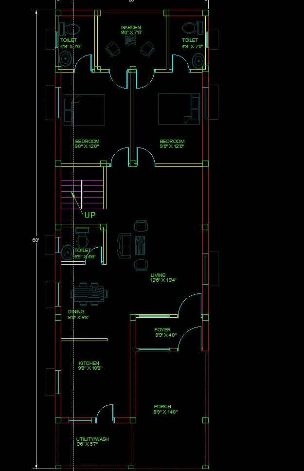
- By using design centre the bedroom, table and chair blocks are inserted.
- By using the single line text the text are created.
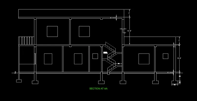
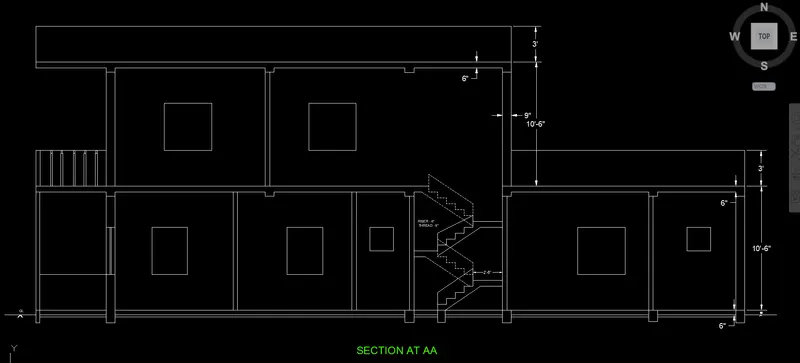
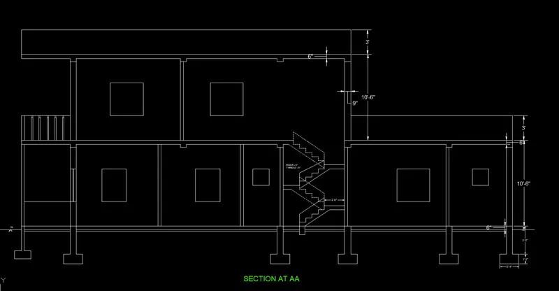
Drawing of the section AA:
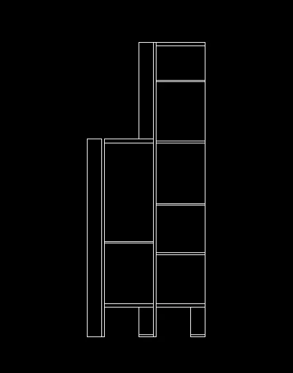
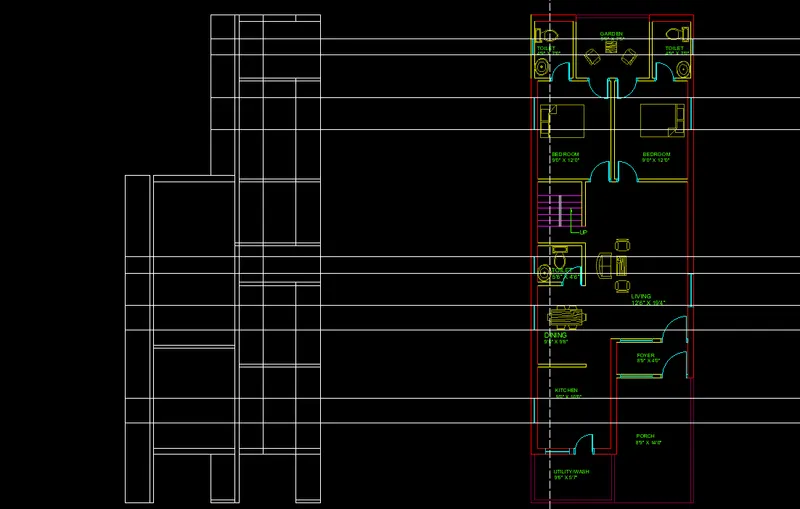
- By using the xline command extend the lines from the walls.
- draw a vertical line by using the line command.
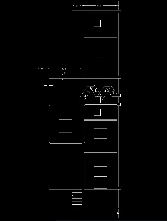
- offset this vertical line by 10', 6", 10', 6" and 3' respectively.
- Trim the unwanted lines.
- Extend the lines from the windows
- offset the floor surface by 3' and 4' respictively.
- offset the slab surface by 3' and 4' respectively.
- trim the unwanted lines.
- Extend the lines from the stairs.
- Draw the riser of 6" and thread of 9"
- copy the whole stair and placed at required position and mirror it.
- for the drawing of the footing the from the GL draw the 3'5" downward and 10" on either side with a footing depth of 1'2".
- By using dimlinear command the dimensions are given.
- By using the single line text the texts are written.
Drawing of the elevation
- By using the Xline command the extend the lines from the walls.
- draw the horizontal line.
- offset the this line by a 10'6", 10'6" and 3' respectivcely.
- By using the xline command extend the lines from the windows and doors.
- offset the horizontal slab surface line by 3' above.
- Trim the all unwanted lines.
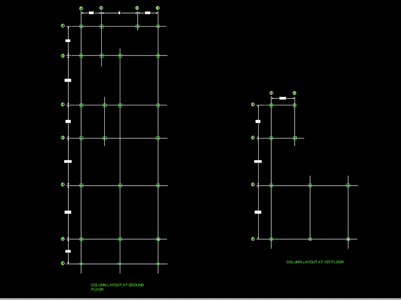
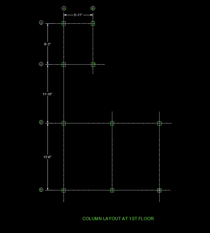
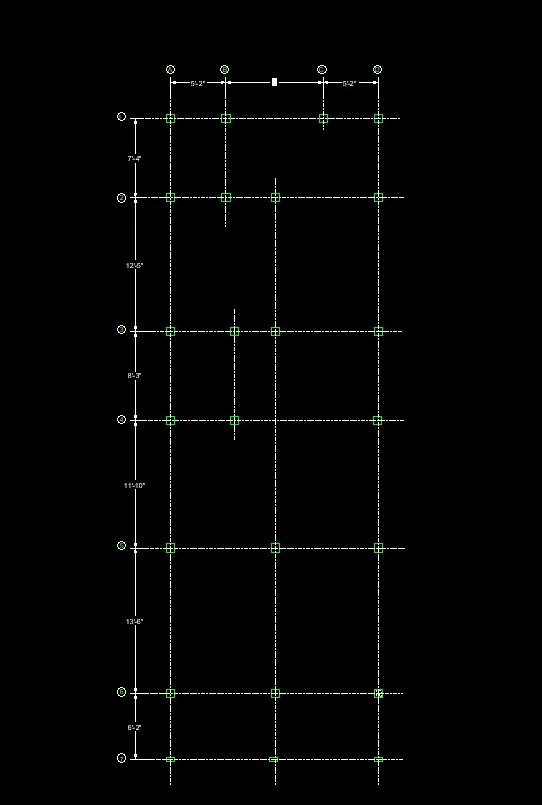
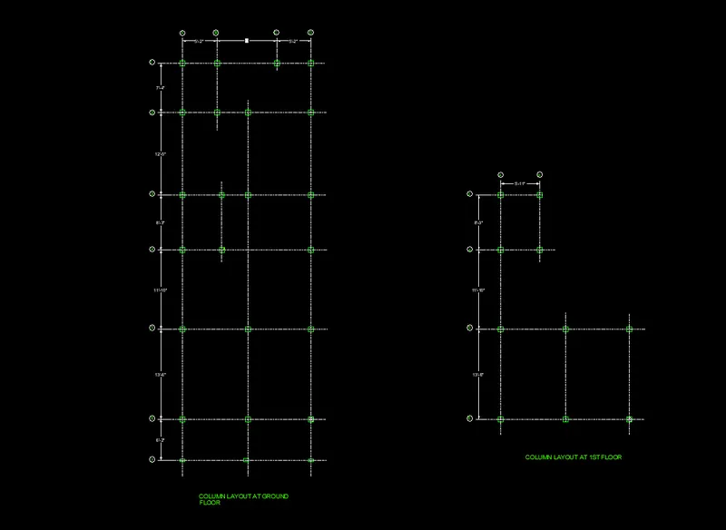
Drawing of the column layout:
- Select the columns which are already placed at the plan drawing and copied at another position
- select the line command and select the linetype as ACAD_ISO02W100
- Draw the line the centre of the column.
- Give the name to all vertical and horizontal line.
- Column schedule as given below.
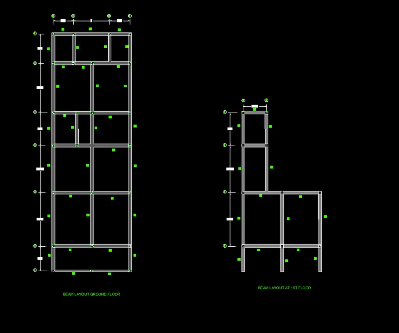
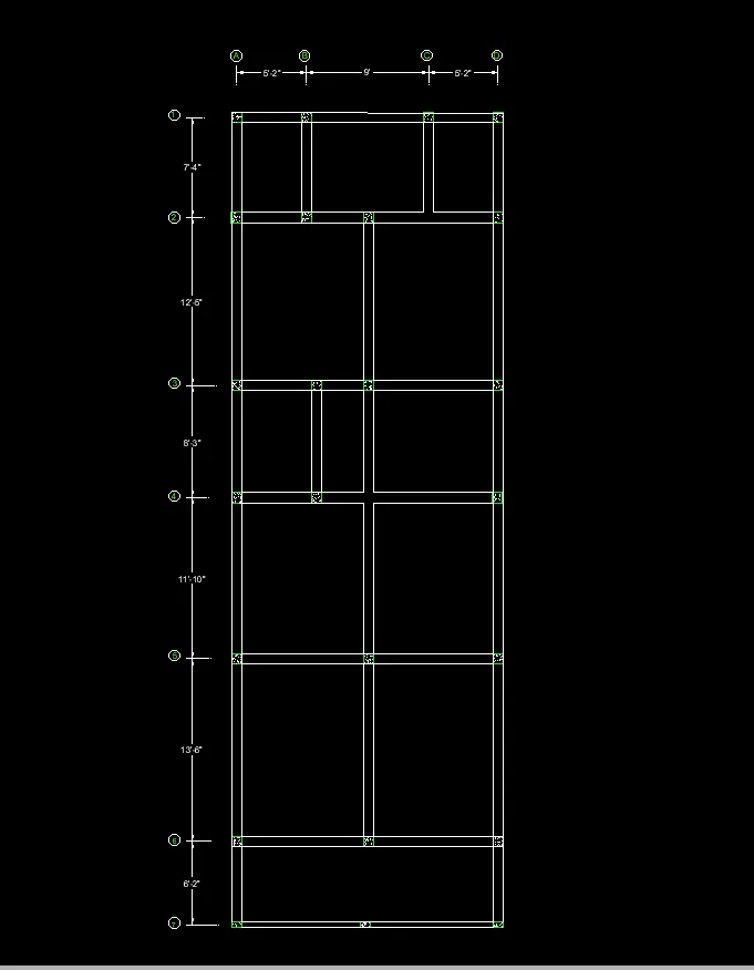
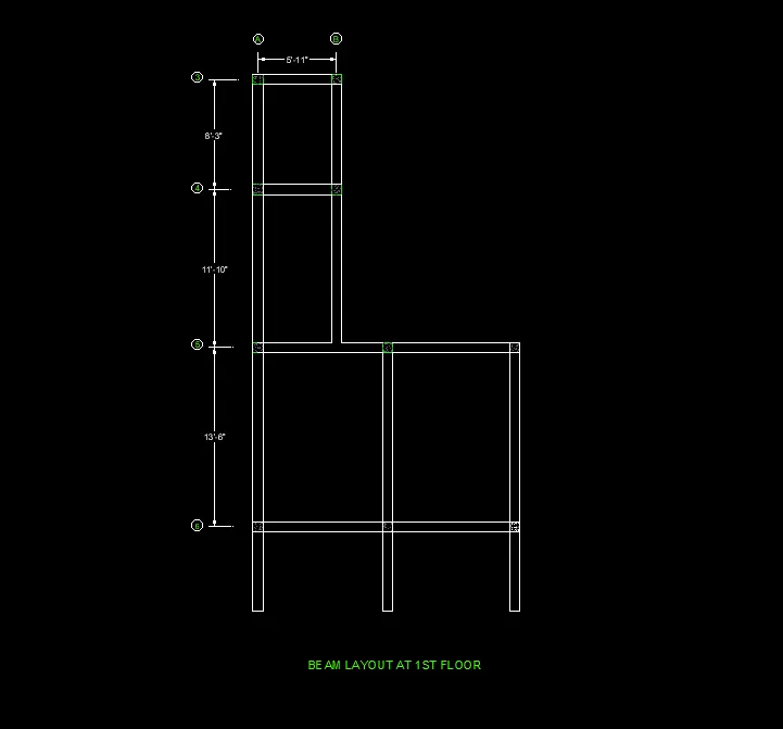
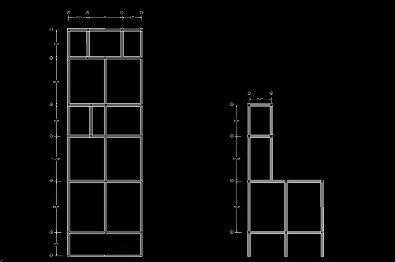
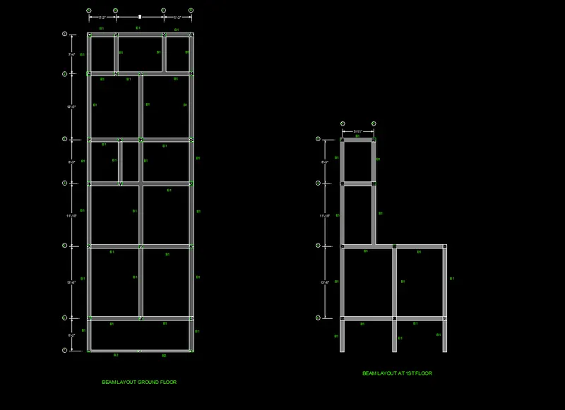
Drawing of the beam layout
- Copy the whole column layout placed it.
- Erase the all centre lines.
- By using the line command all column outer line joined.
- by using the dimlinear command the dimensions are given.
- By using the single line text command the text are written.
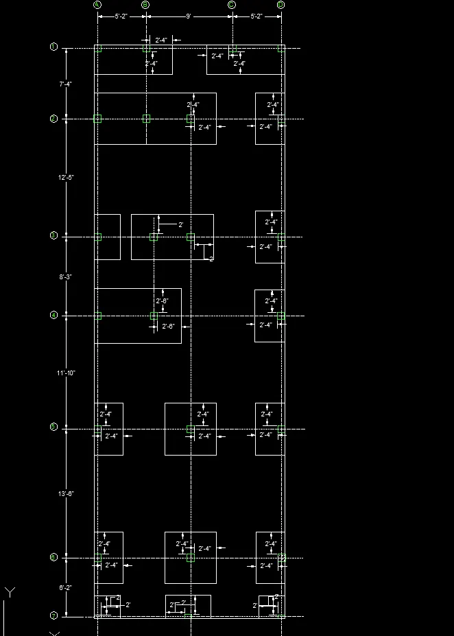
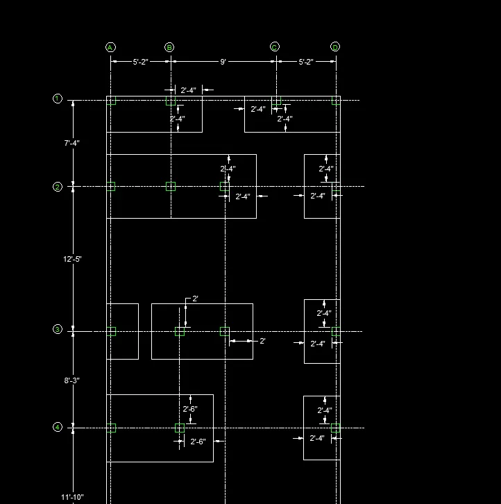
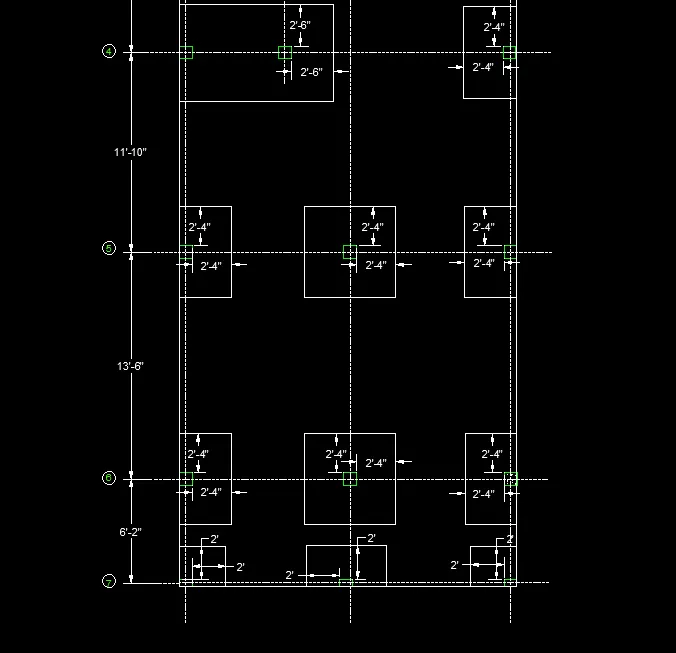
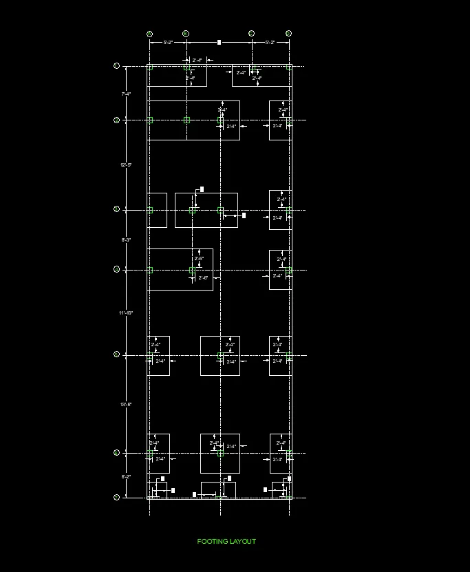
Drawing of footing layout:
- Copy the column layout.
- Offset the column by a offset distance of 2'4" for first columns and trim the unwanted lines.
- The A1 column and B1 columns footings are overlapped therefore the combined rectangular footing is used.
- The front columns footings are offset with offset distance of 2' and trim the unwanted lines.
- by using the dimlinear and dimcontinuous command the dimensions are given.
Result:
The plan is drawn for the plot size of 20' x 60' with the east facing, section, elevation and structural drawings are drawn.