Project 1 _Creating an Architectural plan for the provided plot size and develop relevant basic structural drawings
AIM: To design and draft a layout of a residential building with the following details:
- Plot Size: 60’x20’(18.3m x6m)
- Orientation- Facing East
- Develop the following:
- Architectural Drawing (Floor Plan, Elevations, and Sections)
- Structural Drawing (Column, Bean, Footing Plan)
INTRODUCTION: A plot size of 60' x 20' is given by the challenger, and students are asked to sketch an architectural plan of a building possible inside that plot and also provide the necessary section and elevations as asked. The orientation of the building should be in the east direction. The students are also asked to give structural drawings of columns, beams, and footing plan. The following challenge is to make the student aware of the fact that the designers have to provide the best facilities possible even in less space. The whole project in a step-by-step manner is done and the intermediate snips to show the process of the editing are given below. The snip of the layer properties table is also attached at the end. The whole project is divided into two parts: Architectural plans and sections, Structural drawings. Please check the below attachments of snips to check out the project. The AutoCAD file i.e., with dwd extension is also attached in the attachments sections. For more clarity please check that file.
- Architectural Drawings:
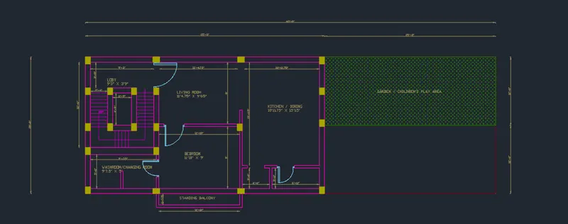
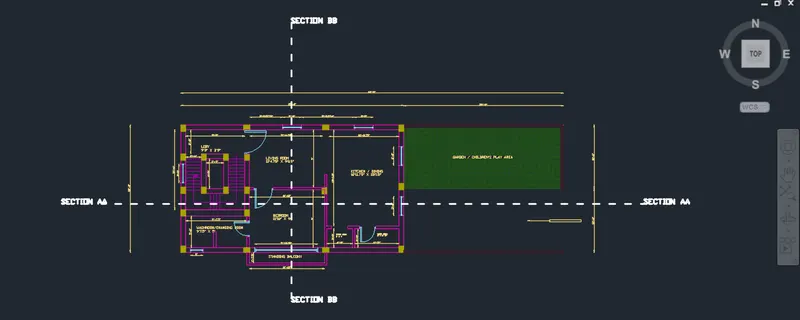
- Floor Plan:
- Procedure:
- Go to the layer properties and create different layers for columns, footing, dimension, walls, doors, windows, etc.
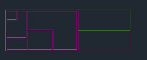
- Take the rectangle command and draw the plot of 60' x 20' in the plot layer.
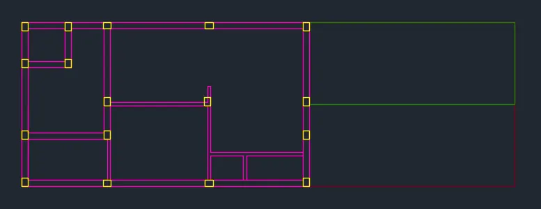
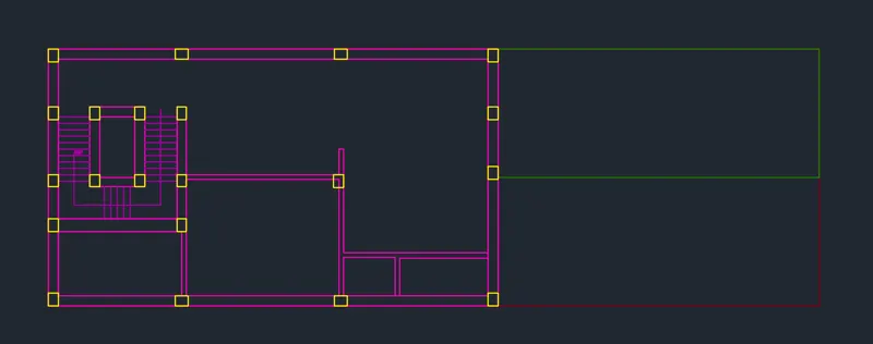
- Now use the line, offset, fillet, trim, extend, etc, commands to draw the plan of the building.
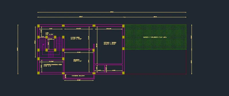
- The size of the building is 35' x 20', and the rest area is allocated to the road and the garden area.
- Once the whole layout is properly planned start giving dimensions and labeling where ever necessary.
- Apply hatch to the columns and garden.
- The layout plan of the building is ready!
- Procedure:
- Elevations:
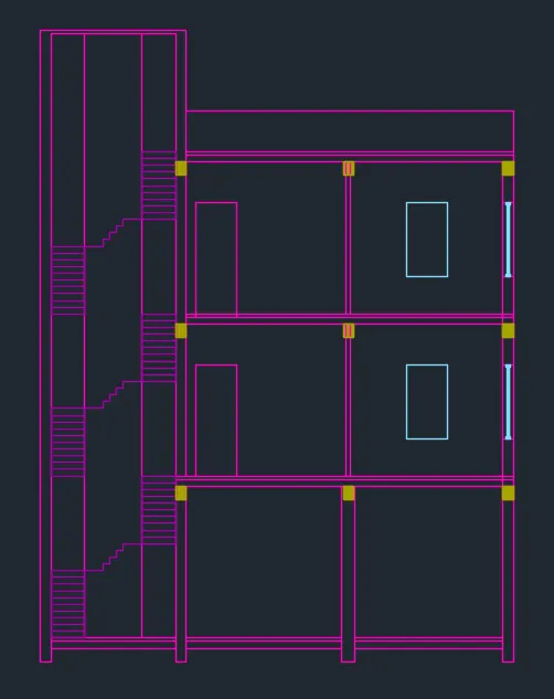
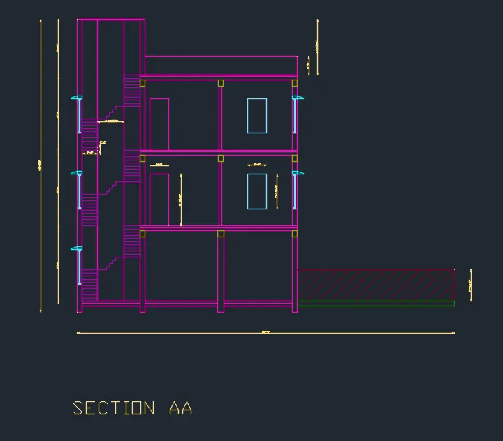
- Section AA:
- Procedure:
- From the layout plan of the building with reference to the section line AA start drawing the section.
- The width of the section is 60' and the height of each floor is given as 12'.
- Draw the section using the line, offset, trim, extend, fillet, xline, copy, etc, commands.
- Once the whole section is drawn give the dimensions and labels wherever necessary.
- Procedure:
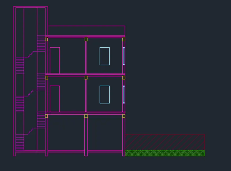
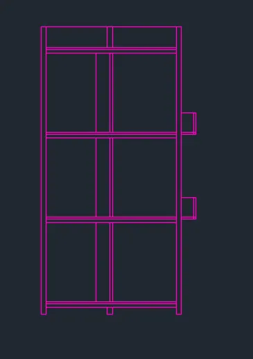
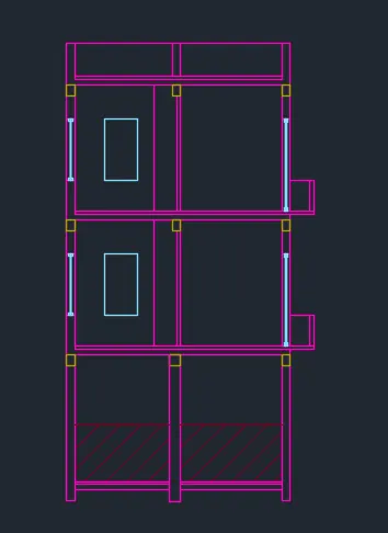
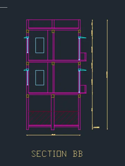
- Section BB:
- Procedure
- From the layout plan of the building with reference to the section line, BB start drawing the section.
- The width of the section is 20' and the height of each floor is given as 12'.
- Draw the section using the line, offset, trim, extend, fillet, xline, copy, etc, commands.
- Once the whole section is drawn give the dimensions and labels wherever necessary.
- Procedure
- Section AA:
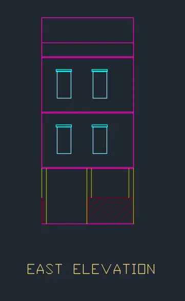
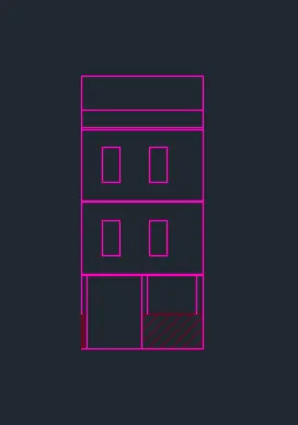
- Elevation:
- Procedure:
- The following elevation is given in the east direction.
- The width of the building is 20' and the height of each floor is 12'.
- Draw the elevation of the building using the line, offset, trim, extend, fillet, xline, copy, etc, commands.
- Once the whole section is drawn give the dimensions and labels wherever necessary.
- Procedure:
- Floor Plan:
- Structural Drawings
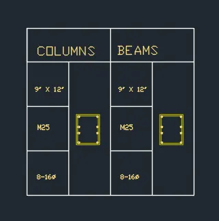
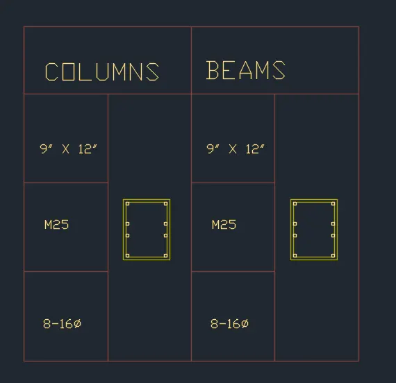
- Columns and Beams Section:
- Procedure:
- Draw the table using a rectangle and offset commands.
- Add the necessary texts using the Dtext command.
- Draw the section of beams and columns using the rectangle command and draw RCC bars into it.
- Thus the specification table showing the sections of the column and the beam can be given like this.
- Procedure:
-
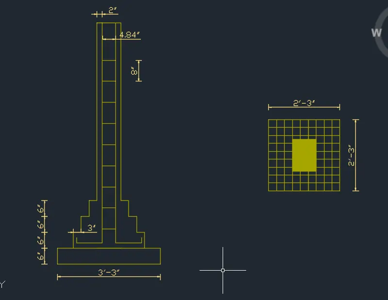
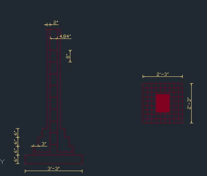
Footing Plan and Section:
- Procedure:
- Draw the section and plan of the footing using rectangle, line, trim and offset commands.
- Once the section and plan are drawn, sketch the RCC bars.
- Once everything is drawn start adding texts and dimensions
- Add the necessary texts using the Dtext command.
- Draw the section of beams and columns using the rectangle command and draw RCC bars into it.
- Thus the specification table showing the sections of the column and the beam can be given like this.
- Procedure:
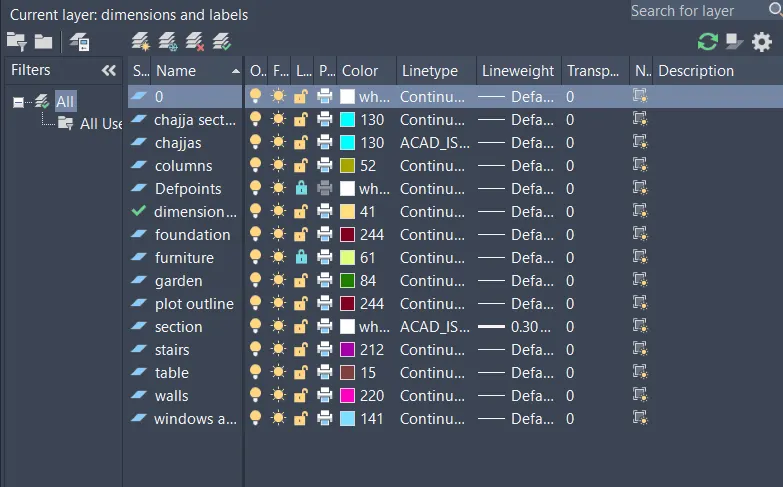
- Layer Properties:
- Below are the properties and the types of layers formed to plot the whole drawing.
- Below are the properties and the types of layers formed to plot the whole drawing.
- Columns and Beams Section:
RESULTS: Thus, from this whole project I have gained some experience to sketch a drawing and design a building plan in a very less area plot. This challenge has also made me come across the problems faced while designing a plan in a very less area plot. Even though the project done is not up to the mark but still has managed to be one of the best challenges for me, as had made a very great impact on my brain to design the building in very small size plots.